
R50/53 Your ULTIMATE R53 Newbie, DIY, and Performance Guide


Your ULTIMATE R53 Newbie, DIY, and Performance Guide
************************************************** *********
INTRODUCTION.
************************************************** *********
Why does this thread exist?
Below are various pieces of info, tidbits, DIY's, and other links that I have been bookmarking, referencing, and using in my short time as an R53 owner. I drive an 03 MCS with over 90,000+ miles. It is my daily driver, and like more-and-more R53's, it is out of warranty. In my short time on NAM, I have been seeing a growing trend of car-enthusiasts getting into the world of Minis with an older, and higher mileage car. I'm hoping that this thread not only serves as a stepping stone, but also as an invaluable resource.
"Hey, idiot, you left out yadda, yaddda!"
No problem, add it into this thread! If you find a source of info that you keep handy for a certain piece of maintenance, performance, etc... POST IT UP! I want to be able to use this as my one stop shop as well. And, I'm hoping it grows into that.
Disclaimer.
I do not have personal experience with every technique posted below, but had simply bookmarked it for future reference. Use the info, as you would any other piece of internet info, at your own risk.
************************************************** *********
HELP, I'M A NEWBIE.
************************************************** *********
How do I buy a Mini?
http://www.motoringfile.com/mini-r50r53-buyers-guide/
How do I reset the ECU?
https://www.northamericanmotoring.co...ni-viagra.html
1. With the key in the ignition, but in the off position, press and hold down the odometer reset button with one hand, while holding the button down, switch the key in the ignition to position 1 (first click) with the other hand.
2. The screen will have a number and the word “tESt”.
3. Scroll through the numbers by pressing the odometer rest button, through to 19 and wait a moment. (Note: the number order is: 1,2,10,19)
4. The message will say 19 "L i-off", flash to "L i-on", and back to "L i-off" again. When "log i-off" appears, press the odometer rest button again. You are now in the system.
5. Scroll through to 21. tESt and wait a moment. 21.0 rESEt will come up. Press the button once.
6. Your gauges will now make some sounds and movements. Once the lights come back on start your car. You have now reset your ECU and your MINI is now ready to relearn the new mods and your driving style.
How do I reset the maintenance counter?
1. Press and hold the trip odometer button.
2. Insert car key and turn it to the first position.
3. Watch for the word "RESET" to appear on the Odometer indicator.
4. Release the trip odometer button, then press & hold it again.
5. Wait for the "RESET" message to flash.
6. Release the button, and then press & release (once only)
7. The Service interval is now reset
How do I reset TPMS?
1. Before a journey, start the engine, but do not start driving.
2. Press the button until the indicator lamp in the display elements lights up in yellow for several seconds.
3. Drive off.
4. Initialization is completed during the drive, without any feedback issued.
How do I get the shift **** off?
Pull straight up, try not to hit yourself in the face.
Why does my clutch sound like Chewbacca?
More than likely you have a glazed flywheel. This is a very common and semi-embarrassing problem. However, does not effect performance, motor on!
What special tools do I need?
Always, always, always invest in the right tools! For typical and likely maintenance, the following (in addition to a regular set of tools) are necessary:
1. Torx bit set, in all sizes.
2. 36mm socket for oil filter housing
3. Serpentine belt removal tool
4. Pulley puller (if removing the supercharger pulley)
5. Bentley Service Manual
6. Beer.
************************************************** *********
KNOWN AND COMMON PROBLEMS.
************************************************** *********
Be sure to check the ‘stickies’ found at the top of each forum.
https://www.northamericanmotoring.co...lems-issues-9/
PS Pump – There are many members having issues with their power steering, and power steering fan failing. If you find yourself needing to replace your fan and/or pump see here:
https://www.northamericanmotoring.co...tructions.html
Thermostat housing – The thermostat housing is prone to warping and leaking. If you have a leak from this area, consider a new thermostat, gasket, and housing.
https://www.northamericanmotoring.co...lems-help.html
https://www.northamericanmotoring.co...hermostat.html
Diagram - http://www.realoem.com/bmw/diagrams/h/n/153.png
Coolant expansion tank – This is another probable source for a coolant leak. The expansion tank sits right above the header. The newest version is an ugly yellow color, but it is a cheap (~$35) and easy fix. Most online vendors stock this part.
Oil pan gasket – The oil pan gaskets are a common area of oil leaks. If you’re dripping oil, check the gasket.
http://r53minicooper.wordpress.com/2...s-r53-summary/
Intermittent Headlights – If you have the stock xenon headlights, and you have one headlight that works intermittently, it is most likely the ballast, or control unit; item 1 in the picture below. http://www.realoem.com/bmw/showparts...23&hg=63&fg=05
Mushrooming shock towers – Many Mini’s experience this, some just far worse than others. See this sticky for all the info.
https://www.northamericanmotoring.co...ollection.html
Rust – Another sticky showing the most common problem spot for rust.
https://www.northamericanmotoring.co...-05-minis.html
************************************************** *********
MAINTENANCE.
************************************************** *********
Oil Change - This is easy, don't sweat it!
http://www.tech-esq.com/Site/Engine/..._Change.html#5
Manual Transmission Fluid Change
http://www.lonestarminiclub.com/foru...read.php?t=474
Brakes
Front - https://www.northamericanmotoring.co...beginners.html
Rear - https://www.northamericanmotoring.co...beginners.html
Brake Fluid Flush - http://www.lonestarminiclub.com/foru...read.php?t=476
Replacing Guide Bushings, Brake lines and brake bleeding techniques incl photos. - Brakes R53.pdf
A favorite brake vendor - http://zeckhausen.com/Mini/MINI_Cooper.htm
Fuel Filter
https://www.northamericanmotoring.co...hange-mcs.html
Serpentine Belt Replacement – See the instructions for supercharger pulley install (below) for more info.
https://www.northamericanmotoring.co...placement.html
How to Replace Mini Cooper Cabin Air Filter:
Info and Photos - http://www.geekshocker.com/Claire/maint/cabinFilter.php
Video- http://www.doityourself.com/video/Ho...lter-208498258
Fault Codes -
http://www.obd-codes.com/trouble_codes/
AC Compressor, Dryer, & Expansion Valve -
http://www.lonestarminiclub.com/foru...=4179#post4179
Service Mode -
https://www.northamericanmotoring.co...front-end.html
Replacing Supercharger and/or Waterpump -
https://www.northamericanmotoring.co...night-diy.html
************************************************** *********
MODIFICATIONS.
************************************************** *********
Exhaust Reference Thread –
https://www.northamericanmotoring.co...clips-etc.html
Intake – A pretty good discussion on Cold Air Intakes
https://www.northamericanmotoring.co...which-cai.html
How To: http://www.m7tuning.com/techinfo/ins...m7-r53-cai.pdf
Supercharger pulley – A good discussion on pulleys
https://www.northamericanmotoring.co...r-pulleys.html
How To: - http://www.mini-madness.com/pdf_file...EY_INSTALL.pdf
Rear Anti-swaybar - Another highly recommended modification
What is Understeer? https://www.northamericanmotoring.co...-question.html
Rear swaybar info - https://www.northamericanmotoring.co...r-dilemma.html
How To: https://www.northamericanmotoring.co...ll-how-to.html
Lighting – All of your bulb info needs!
https://www.northamericanmotoring.co...-cooper-s.html
Personally, I have had good experience with http://www.bimmian.com/. Their interior bulb package has worked well for me, and I enjoyed the color of the license plate bulbs without having to go to LEDs. (There are issues with LEDs in the license plate locations. See https://www.northamericanmotoring.co...lbs-issue.html)
For the exterior, I have found the Halo Ices Blue in H7 and H11 to be a pretty good color match to the stock xenon. They are rated at 4,500k, and are relatively inexpensive at $17/pair. I got mine off Amazon.com.
Installing a boost gauge –
https://www.northamericanmotoring.co...e-install.html
Retrofit of an aftermarket HID kit for OEM Halogen Headlights.
DIY Xenon HID retrofit Instructions.pdf
DIY Dual Gauge Bracket ( Nice work Plasticknives ! ):
https://www.northamericanmotoring.com...ml#post2975561
Installing tachometer and speedometer faces.
https://www.northamericanmotoring.com...with-pics.html
Cheap DIY Modifications - For when you're bored and don't feel like spending too much money.
https://www.northamericanmotoring.co...ification.html
R50/R52/R53 - Removing and Installing Mirror Caps. Thanks to imagoX !
https://www.northamericanmotoring.com...the-clips.html
************************************************** *********
Miscellaneous.
************************************************** *********
A GREAT source of info, including an extensive DIY section –
http://www.soopercooperinfo.com/
Another great source of DIY's -
http://www.mini2.com/forum/faq.php?f..._obc_functions
For finding part numbers, diagrams, etc.
http://www.realoem.com/bmw/select.do
This is too cool –
http://maps.google.com/maps?f=q&sour...,0.001698&z=19
Please add anything else that I have missed, or expand on anything that I didn't quite get right. AND, if you're local and working on your car, drop me a line! There's only so much you can learn on your own car.
Zach
Last edited by shorty_du_op; Jul 8, 2011 at 09:42 AM.

This thread is stickied. I just wanted to commend you in taking the time and effort to gather everything into one place. A lot of the information you posted is common general questions and I think it's a great thread to point to for answering a lot of those questions.
How to Replace Mini Cooper Cabin Air Filter:
Info and Photos:
http://www.geekshocker.com/Claire/maint/cabinFilter.php
Video:
http://www.doityourself.com/video/Ho...lter-208498258
DIY Dual Gauge Bracket ( Nice work Plasticknives ! )
https://www.northamericanmotoring.co...ml#post2975561
Info and Photos:
http://www.geekshocker.com/Claire/maint/cabinFilter.php
Video:
http://www.doityourself.com/video/Ho...lter-208498258
DIY Dual Gauge Bracket ( Nice work Plasticknives ! )
https://www.northamericanmotoring.co...ml#post2975561
Last edited by -=gRaY rAvEn=-; Feb 8, 2010 at 06:00 AM.
I just added in some info on rear sway bars as well. I found a few of those questions popping up lately, and I'm about ready to venture into the suspension relm as well.
-=gRay rAvEn=-, I added that info above, thanks much! If you didn't notice, there are a few of your threads referenced above. I appreciate your contribution and input in the NAM community, as I'm sure many other do.
Xenon HID Retrofit kit
Thanks, always happy to contribute and help out.
Here is another DIY which seems to be gaining some popularity.
PDF Instructions - Retrofit of an aftermarket HID kit for OEM Halogen Headlights.
DIY Xenon HID retrofit Instructions.pdf
And I included some pics in this thread - Where to mount ballast in the 1st Gen MINI.
https://www.northamericanmotoring.co...og-lights.html
Last edited by -=gRaY rAvEn=-; Feb 16, 2010 at 04:15 AM. Reason: Added Second Thread Link
Brakes R50/52/53
Trending Topics
Installing upgraded Speedo/Tach faces
Instuctions for installing tachometer and speedometer faces.
https://www.northamericanmotoring.co...with-pics.html
https://www.northamericanmotoring.co...with-pics.html

All DIY's added! 
I am currently working on an AC maintenance section, but I want to wait until my Bentley manuals come in so that I can include some troubleshooting techniques as well.
I am currently working on an AC maintenance section, but I want to wait until my Bentley manuals come in so that I can include some troubleshooting techniques as well.

2nd Gear
Joined: Apr 2009
Posts: 52
Likes: 0
That would be an awesome DIY!
R50/R52/R53 - Removing and Installing Mirror Caps. Thanks to imagoX !
https://www.northamericanmotoring.co...the-clips.html
https://www.northamericanmotoring.co...the-clips.html

6th Gear
Joined: May 2007
Posts: 3,789
Likes: 10
From: Kansas City

Neutral
Joined: Dec 2008
Posts: 6
Likes: 0
thanx to shorty and mini dave. i just replaced my ps pump, purchased from bbreman and it still requires a lot of muscle to park! I repaced the pump with a friend who is a professional mechanic ,ie had a lift etc. It wasn't too difficult a job. Made sure the connections were good and bled the system as required by the instructions that came with the rebuilt unit. You could hear the pump running only briefly while I was bleeding it, then just quit. I am ordering a Bentley manual to try to get some more info, such as a relay or other electrical things to check. Yes I have checked the fuses. Any input would be greatly appreciated.
4th Gear
Joined: Jul 2009
Posts: 385
Likes: 4
REAL OEM
This is a well known (and very beneficial) site for all the DIY'ers:
http://www.realoem.com/bmw/select.do
http://www.realoem.com/bmw/select.do
This is a well known (and very beneficial) site for all the DIY'ers:
http://www.realoem.com/bmw/select.do
http://www.realoem.com/bmw/select.do
It's already up there. However, I did add the link that you emailed me, thank you very much!@
4th Gear
Joined: Jul 2009
Posts: 385
Likes: 4
BMW CODES
I tried to add the fault codes but the list was waaaaayyyy too long for a post. Maybe there is a "man behind the curtain" that has the capability to add them........
Or we can just go to this website: http://www.obd-codes.com/trouble_codes/
Or we can just go to this website: http://www.obd-codes.com/trouble_codes/
Last edited by DMBFan2; Mar 1, 2010 at 08:21 AM.
4th Gear
Joined: Jul 2009
Posts: 385
Likes: 4
Repair Electric Window Motor and Regulator
Taken from:
http://www.z50ak1.com/mini/default.htm
More information with photos:
http://www.mini2.com/forum/first-gen...ing-guide.html
So your MINI Cooper's electric window doesn't work anymore and you checked the fuses and they are OK.
When you lift the switch you can hear a clicking sound from inside the door. You maybe found some info on the web about the motor being burnt out and maybe trying to pound the door just above the speaker to see if this jars the motor back to working order but nothing.
The following describes how to fix the problem.
I am telling how to do this without photos but you won't need them.
First get a new motor. Be sure to specify either driver or passenger side. They are $114 from BMW.
Depending, you may need a new regulator assembly. They are $141 from BMW. It may make sense to get the whole assembly when buying a new motor. If you find you need one you will have to go back to BMW again. It also makes things somewhat easier and you end up with a complete A-1 job. And finally, if you have BMW do this job it will cost much, much more than you are paying for these parts.
I think that when this job is done at BMW they are replacing the entire assembled regulator complete with new motor.
This job takes 1-2 hours.
First you will need the following tools:
Now remove the door panel by removing (4) #30 torx screws in the door. The fourth screw is under the clear reflector at the edge of the door. Pry that out with your small screw driver (if this piece separates don't worry it will be OK).
Pry the panel off with the pry tool.
Now the glass must be removed. The window is secured with two nylon clamp washers that clamp the glass to the regulator. Reaching into the door cavity, and up, you can feel for them. They are a sprocket like device that are supposed to require BMW special tool 51 3 240. BMW wouldn't sell me one but you can remove them by using your 5mm or 3/16" allen wrench. Feel carefully and you will find the center of the sprocket where the allen will fit into. Loosen these sprockets and remove them. Remove the glass straight up.
From the outside of the car, using your fingers, carefully remove the outer door top trim piece.
Remove the speaker and 3 phillips head screws on the door handle.
Remove two round black seals near the top of the door, one on the left and one on the right.
Standing outside of the car and looking down into the door cavity from the top, you can see two white plastic nylon clips that secure the cable assembly to the inside of the door. Carefully remove these clips with a pry tool. If these break you will have to figure something out. If you have a new regulator assembly it doesn't matter.
Remove the third cable clip from the inside of the door.
Remove three phillips head screws just above the speaker opening that secure the motor to the door.
Remove two 10mm bolts from under the bottom of the door.
Remove two 10mm bolts from the top of the regulator rails.
Carefully remove the regulator assembly and disconnect the electrical cable.
Lie it down flat and take note of and make a visual reference of the motor in relation to the cable mechanism. Or just take a photo.
Remove (1) #20 torx screw that attaches the motor assembly to the rail. Remove the motor assembly from the rail.
To replace the motor, just *LOOSEN* only, about 1/8 inch, four #20 torx screws that mount the motor to the cable assembly.
Pry the two parts apart enough to open a 1/8 inch space. Place your putty knife between the motor and the cable assembly to hold down and prevent the cable reel from coming apart when you separate the two pieces. (if this comes apart you might need a new regulator assembly.)
Completely remove the four screws and separate the motor from the cable assembly.
Using your visual reference if needed, assemble the new motor to the cable mechanism.
Attach the motor assembly to the rail.
Place assembly into the door cavity taking this time to reattach the electrical cable to the motor.
Using a 10mm socket hand tighten the two top rail screws.
Using a 10mm socket hand tighten the two bottom rail screws.
Connect and put the speaker back in.
Secure the motor to the door with (3) phillip head screws.
Looking down from the top and reaching into the door cavity from the side, insert the plastic cable tie clips into the inside of the door. Insert the third cable tie clip into the inside of the door.
Place the glass back into the door and hand tighten the sprocket window clamps.
Replace the top outside trim piece (compare with other door).
Attach the battery negative connector.
With the door open raise the window completely.
With the sprocket clamps hand tight, you may now adjust the window left or right and up or down as needed.
With the door slightly closed and ajar in the first click position, the window should be square and touching the rubber seal gently (use a piece of paper to feel the pressure).
To adjust this, move the bottom of the rails in or out to tilt the window as needed. Too tight and there is stress on the window. Too loose and you hear the wind when you are driving and maybe even water gets in.
Compare with the other door.
Take your time, and when you are satisfied and happy with the window adjustments, use your allen wrench to tighten the clamps good and snug, but not too much (about 10 foot pounds).
Fully tighten the (4) 10mm bolts that secure the rails. Replace the rubber seals that cover the 10mm screws. Replace the door handle.
Put the door panel back on and replace the reflector.
To finish off, with the door closed, lower and raise the window completely, and when fully raised, hold the switch in the up position for 10 seconds. This reprograms the GWC.
When you shut the door completely with the window fully raised, the motor raises the window about a 1/4" just after the door shuts. When you open the door, it lowers it about a 1/4".
To reset your clock back to a 12 hour clock, depress both buttons on the clock simultaneously and hold for 5 seconds.
http://www.z50ak1.com/mini/default.htm
More information with photos:
http://www.mini2.com/forum/first-gen...ing-guide.html
So your MINI Cooper's electric window doesn't work anymore and you checked the fuses and they are OK.
When you lift the switch you can hear a clicking sound from inside the door. You maybe found some info on the web about the motor being burnt out and maybe trying to pound the door just above the speaker to see if this jars the motor back to working order but nothing.
The following describes how to fix the problem.
I am telling how to do this without photos but you won't need them.
First get a new motor. Be sure to specify either driver or passenger side. They are $114 from BMW.
Depending, you may need a new regulator assembly. They are $141 from BMW. It may make sense to get the whole assembly when buying a new motor. If you find you need one you will have to go back to BMW again. It also makes things somewhat easier and you end up with a complete A-1 job. And finally, if you have BMW do this job it will cost much, much more than you are paying for these parts.
I think that when this job is done at BMW they are replacing the entire assembled regulator complete with new motor.
This job takes 1-2 hours.
First you will need the following tools:
- #20 and #30 Torx screw drivers.
- Medium Phillips head screwdriver.
- 10mm socket and ratchet wrench.
- 5mm or 3/16" Allen wrench.
- Door panel pry tool. (get at auto parts store)
- A small precision screw driver
- Stiff putty knife.
Now remove the door panel by removing (4) #30 torx screws in the door. The fourth screw is under the clear reflector at the edge of the door. Pry that out with your small screw driver (if this piece separates don't worry it will be OK).
Pry the panel off with the pry tool.
Now the glass must be removed. The window is secured with two nylon clamp washers that clamp the glass to the regulator. Reaching into the door cavity, and up, you can feel for them. They are a sprocket like device that are supposed to require BMW special tool 51 3 240. BMW wouldn't sell me one but you can remove them by using your 5mm or 3/16" allen wrench. Feel carefully and you will find the center of the sprocket where the allen will fit into. Loosen these sprockets and remove them. Remove the glass straight up.
From the outside of the car, using your fingers, carefully remove the outer door top trim piece.
Remove the speaker and 3 phillips head screws on the door handle.
Remove two round black seals near the top of the door, one on the left and one on the right.
Standing outside of the car and looking down into the door cavity from the top, you can see two white plastic nylon clips that secure the cable assembly to the inside of the door. Carefully remove these clips with a pry tool. If these break you will have to figure something out. If you have a new regulator assembly it doesn't matter.
Remove the third cable clip from the inside of the door.
Remove three phillips head screws just above the speaker opening that secure the motor to the door.
Remove two 10mm bolts from under the bottom of the door.
Remove two 10mm bolts from the top of the regulator rails.
Carefully remove the regulator assembly and disconnect the electrical cable.
Lie it down flat and take note of and make a visual reference of the motor in relation to the cable mechanism. Or just take a photo.
Remove (1) #20 torx screw that attaches the motor assembly to the rail. Remove the motor assembly from the rail.
To replace the motor, just *LOOSEN* only, about 1/8 inch, four #20 torx screws that mount the motor to the cable assembly.
Pry the two parts apart enough to open a 1/8 inch space. Place your putty knife between the motor and the cable assembly to hold down and prevent the cable reel from coming apart when you separate the two pieces. (if this comes apart you might need a new regulator assembly.)
Completely remove the four screws and separate the motor from the cable assembly.
Using your visual reference if needed, assemble the new motor to the cable mechanism.
Attach the motor assembly to the rail.
Place assembly into the door cavity taking this time to reattach the electrical cable to the motor.
Using a 10mm socket hand tighten the two top rail screws.
Using a 10mm socket hand tighten the two bottom rail screws.
Connect and put the speaker back in.
Secure the motor to the door with (3) phillip head screws.
Looking down from the top and reaching into the door cavity from the side, insert the plastic cable tie clips into the inside of the door. Insert the third cable tie clip into the inside of the door.
Place the glass back into the door and hand tighten the sprocket window clamps.
Replace the top outside trim piece (compare with other door).
Attach the battery negative connector.
With the door open raise the window completely.
With the sprocket clamps hand tight, you may now adjust the window left or right and up or down as needed.
With the door slightly closed and ajar in the first click position, the window should be square and touching the rubber seal gently (use a piece of paper to feel the pressure).
To adjust this, move the bottom of the rails in or out to tilt the window as needed. Too tight and there is stress on the window. Too loose and you hear the wind when you are driving and maybe even water gets in.
Compare with the other door.
Take your time, and when you are satisfied and happy with the window adjustments, use your allen wrench to tighten the clamps good and snug, but not too much (about 10 foot pounds).
Fully tighten the (4) 10mm bolts that secure the rails. Replace the rubber seals that cover the 10mm screws. Replace the door handle.
Put the door panel back on and replace the reflector.
To finish off, with the door closed, lower and raise the window completely, and when fully raised, hold the switch in the up position for 10 seconds. This reprograms the GWC.
When you shut the door completely with the window fully raised, the motor raises the window about a 1/4" just after the door shuts. When you open the door, it lowers it about a 1/4".
To reset your clock back to a 12 hour clock, depress both buttons on the clock simultaneously and hold for 5 seconds.
4th Gear
Joined: Jul 2009
Posts: 385
Likes: 4
Istalling LEDS
The following information was taken from:
https://www.northamericanmotoring.co...ght-steps.html
Wiring aside (a good book on DC wiring or car stereo wiring will be a good start), here's the process for the PHYSICAL strip installation on a 1st Gen MINI (2002-2006). For the R56 forward, the battery terminal may be in a different place, and I'm not sure about the side skirts.
Note that I do not warranty this installation and you must proceed at your own risk. If anything here seems beyond your comfort level, have a trained stereo or underbody glow installer do the work.
Tools/Supplies needed:
Before you do anything, I'd test the LED strips to make sure they work - I've never had one bad out of the box, but if one is bad then you really really REALLY want to find out BEFORE you get them on the car - nothing will **** you off more than getting all the way to the point where you flip your switch only to have 3 of your 4 Strips light up, believe me.
To test LEDs, I use a PC power supply rigged up to use as a test device. Any PC power supply will do (your geek friend that wprks on PCs probably has a few lying around in boxes - just ask him/her), or you can order one HERE. PC repair places often have a big box of perfectly good, used power supplies for like $5-$10. To use a PC power supply out of a computer takes a small modification and about 2 minutes of time - instructions are on the linked page in the sentence before last. I used 'Gator clips on my modded power supply so I could connect the Strips to the power supply and flip the switch.
If you happen to get a bad strip (they're mass produced and fauls can happen) then just email Phil at Oznium - he's wonderful and will do a "no questions asked" replacement.
Physical Installation of LED strips:
1. Jack the car up on jack stands - use 4 stands, one per jack point. To make jacking easier, lay a 2X4 along the side rail between the jack points and jack the entire side from the center of the board. This way, you can put one stand in front and one in the rear at the same time, which is a huge time-saver. When the car is up on the stands, push it HARD to make sure that it won't fall off - it shouldn't move AT ALL. Remember SAFETY FIRST and NEVER, NEVER, EVER crawl under a car sitting on just a jack!!!!
2. For a MINI you'll need two 3' sections and 2 6' sections of Beefy Strip. Plan to install the side strips (the long ones) with the wires facing TOWARDS THE ENGINE - I'll explain why in the wiring section.
3. FOR SIDES AND FRONT - use chalk and a tape measure to make marks every 6". I used the plastic side rail shrouding and it held great. Here's where I made my marks so I could wrap the zip-tie through two holes:
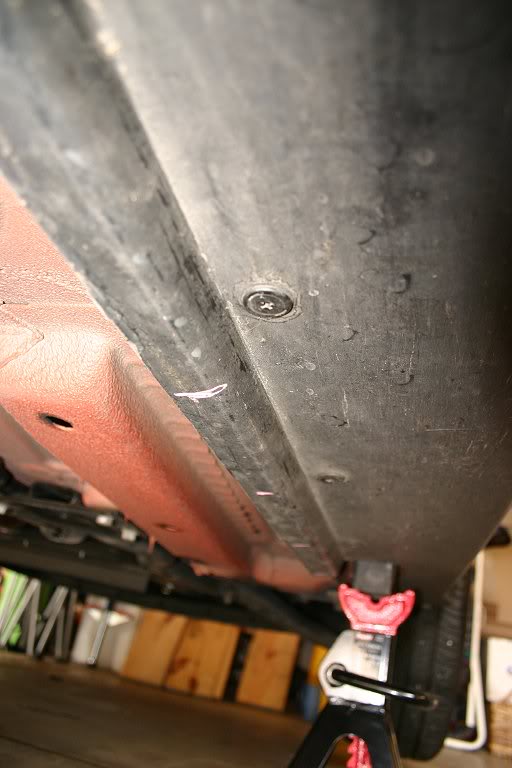
3. Using a 1/4" drill bit, drill the holes. Use a piece of scrap steel or thick aluminum between the plastic rail and the bottom steel of the car (just pull the plastic down and slide it inside) so you don't mar the rustproofing or (worse) hole the underbody or nick a fuel line when the drill goes through. Note that I drilled TWO holes, one inboard and one outboard - this will let me slip the zip-tie across the Beefy Strip for maximum hold.

4. Zip-tie the beefy Strips to the plastic. Note how I put the clamp end INBOARD to hide it visually. The 6' strips are a bit longer than the lengh of the side of the car - I zip-tied the extra bit to the angled stiffener strut that runs just fore of the rear wheel with no issues even after months of hard driving.

5. When you're sure that everything's secure, snip off the remainder ends of the zip-ties and move to the front. For the front, I put the LEDs just BEHIND the little air-dam lip that hangs down - that way the air dam plastic takes the hit if you bottom out in a driveway and not the LEDS. Doing this in no way diminishes the glow, don't worry. use the same chalk-mark/drill/zip-tie process as the sides:

6. FOR THE REAR: The rear is very cramped with no place to really stealth the LEDS. Plus the hot exhaust is back there. Here's how I did it and the LEDs showed just a little bit (you can see them in my photos). When I do this again, I'll get a peice of 90-degree black plastic "L" channel and make baffles, but this will get you lit and running without the LEDs showing TOO much. I drilled my zip-tie holes along the bottom edge of the rear valence (this is the stock valence - Aero-kit owners migt find something different). Make the holes as far back as possible to move the LEDs as far under the car as you can. To go across the exhaust heat sheild, bend the LED strips as illustrated. The heat sheild does get warm, but even after doing lots of stop-and-go driving in the summer, the sheild should not get hot enough to melt the LEDS - mine never did anyway:

WIRING:
I wired my LEDS in PARALLEL as opposed to in series - this was because if I wired in series I'd lose ALL the LEDS if one failed. Replacing only one strip in the event of a road hazard hit would be easier this way as well. if you don'tknow what I mean about wiring, see THIS THREAD on Oznium for basic wiring diagrams. NOTE: If you're scared of wiring (many are) then you can just do the steps above to physically install the accessories and then have a car stereo or car underbody installer do the actual wiring. There's no shame in calling in a pro if you're less than certain you can do the electrical part.
For this install, I used the diagram below, substituting a Beefy Strip for each individual LED. Note also that "load resistors" are not needed with Beefy Strips - they are built into the strip itself and are fully self-contained:
WIRING STEPS:
1. DISCONNECT THE BATTERY - remove the negative battery terminal from the battery (located in the boot on most 1st Gen MINIs) and push it aside so that it does not make accidental re-connection with the battery. This assures that you won't fry your electrical system. I cannot stress this step enough - never do ANYTHING to a car's electrical system until you disconnect the battery - you have been warned!
2. Check your wire lenghts- the Beefy Strips have fairly long leads, and if you did as I instructed and installed the strips with the wire ends toward the front then you probably won't even need to add extra wire on the side Strips or the front Strip. If you do need to add wire, you can crimp on extra wire using butt-caps - use red on the positive lead and black on the ground. When using caps, cover the butt-caps with TWO layers of heat-shrink material to keep water out. Cut the heat-shrink tubing to be at least 1" longer then the cap on either end. You'll definitely need to crimp-on extra wire for the rear Strips - you can tuck them inside the plastic side rail, threading them through the zip-ties holding the beefy Strips to hold them in place.
3. When you get to the front of the car, run your black/red wires up inside the plastic wheel shroud (so they won't get hit by anything the wheels kick up) and up towards the front fender(s). You won't have to drill the fenders - you can pull them down and slip the wires through (illustrated below). You may want to use a double-layer of heat-shrink over the wires where they pass through this "pinch point" to keep the wires from rubbing and eventually fraying - I did. Once the wires are through the fender peice, zip-tie them to the existing wire loom (there's another one just like it on the driver's side) - be sure to give yourself about an inch of slack between the pass-through point and the zip-tie to account for everyday driving movement (not shown):
(NOTE: in the pic above, the wires are the stock Beefy Strip wiring and not the red/black crimped-on wires from the rear - those were threaded through after this photo was taken using the same path. You can also see above the side wiring pass-through where the stock wiring (black electrical tape-wrapped wire) goes into the engine bay - note this as you'll need to use the one on the driver's side for your ground wires. You'll end up with 4 sets of wires, 2 sides and a front/rear all told)
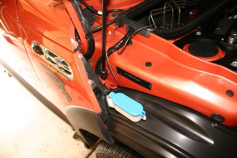
4. Run all your red wires towards the positive battery terminal just beside the air box. Run all your black wires towards the bonnet support on the driver's side - there's a nut there that's a grounding point. You can use the rubber sealent stripping on top of the air box dam and near the bonnet seal to stealth the wires - just pull it off, stuff the wires into the strip using a spoon or chop-stick (not a screwdriver, which can tear the wiring cover) and replace with the wires safely stowed inside:

5. Using the white electrical tape and Sharpie, put a little tape flag on each set of red and black wires (L. side, R. side, frint, rear) - this will help you if you ever need to replace a single Strip in the event of an accident.
6. Connect all positive wires into one bundle and crimp on a butt-cap with all 4 wire leads inside.
7. SWITCH WIRING: Run your switch wiring through the firewall pass-through and into the cabin. Inscructions on how many wires you need and where they connect to the switch should be included with the switch - non-illuminating switches use only 2 red wires (power/accessory) and light-up switches use 3 - 2 red and a black (power/accessory/ground). Oznium's switches come pre-installed with crimped-on terminal plugs, making them very convenient to wire.
If you don't know where the cabin pass-through is, it's right here:

Just push the wires through then open the knee bolster on the driver's side and look UP towards the dash - you'll see your wires poking through. Pull enough slack to reach to wherever you want to install the switch and connect the leads to the switch (instructions should be included with your switch).
8. FOR THE POSITIVE LEADS: Crimp on a ring-terminal to one end of your fuse holder. YOU MUST MUST MUST USE A FUSE NO EXCEPTIONS - this will spare your car from a fire in case of a short. You can tuck the fuse holder on the driver's side space next to the air box.
9. Using a butt-cap, connect the red POWER switch lead to the other end of the fuse holder -this insures that current flows from the terminal then through the fuse before it goes ANYWHERE, (especially the switch your finger will be touching). You may want to nsulate the butt-cap with heat-shrink to keep out moisture.
10. Connect the other switch lead (ACCESSORY) to the butt-cap attached to your 4 positive Strip leads. This ACCESSORY wire receives current when the switch is flipped to the "on" position.
OPTIONAL: You can cover the 4 Beefy Strip positive wires with a bit of split-loom wiring cover, available at any Radio Shack. This will visually stealth the bright red wires and insulate them from physical harm to boot.
11. FOR THE GROUND WIRES: Look for a hat nut with a thick black wire attached to it just aft of the driver's side bonnet support - this is your grounding point. Remove the hat nut.
12. Run all your black Strip wires to this grounding nut - there's a pass-through in the plastic shrouding under the rubber weather stripping.
13. For the cleanest-looking install, Gather all 4 black wires just inside the driver's side pass-through and crimp on a butt-cap. If your switch is illuminated and requires a ground, add this black wire to the bundle. Attach a length of 16-gauge wire (black) to the other end, then run that through the pass-through on the driver's side plastic wall. Then crimp on a ring terminal to the other end of that single 16gauge wire. Slip the ring terminal onto the post and replace the nut. This serves as a shared grounding point for all 4 LED Strips as well as your illuminated switch (if yours lights up).
CONCLUSION:
So, now, in theory, you should have a complete electrical path: DC current goes from the positive battery terminal in the boot, up to the bonnet and the positive accessory terminal beside the air box. From there, it goes into your ring terminal attached to the thumb screw/post, then through the fuse and from there into the cabin and the POWER wire in your switch. From the switch, current passes back into the engine bay along the ACCESSORY wire and into the 4 red positive LED wires and into the accessories. From the strips, it goes through the ground (black) wires and to the grounding point, then back to the battery through the car body steel. This is a circuit.
All you need now is juice. Assuming you made good, solid crimps and insulated everything with heat-shrink tubing, you should have no shorts. Have a helper re-connect the battery ground lead, watching carefully for smoke or any noise. In theory, if you have something accidentally grouding the fuse should pop instantly, but better safe than sorry. If all is OK (it should be) have your helper switch on the LEDs - they should light up. If they don't check your fuse - if it's broken then something is grouding. Disconnect the ground on the batterey and start tracing wires, looking for any place where wires are touching metal. If the fuse is intact, you have a wire loose - if only one Strip doesn't light then check just that one - if all 4 refuse to light then you need to check the bundled connections under the bonnet.
Note that since you're hooking to the accessory terminal under the bonnet (which is "always on") the LEDs will light even with the key out of the ignition. This is good if you want to park your car at a night car show or event and leave the glow on with the doors safely locked and the key in your pocket. Never fear: LEDs are very low-power devices - 18 feet of strips only draw <3A of power, so even if you leave them on for hours your car should start right up, assumiung the battery is good.
This was an overview, I know, so if anyone has any SPECIFIC questions then please let me know.
Happy wiring!!
EDIT: For engine lighting, you can use Beefy Strips or their much cheaper LED Flex Strips (4.7' are only $7 and they're 100% waterproof!) or even Cold Cathodes - all are DC and all follow these same basic installation steps (the fuse you end up using will be different - contact me to calculate the required fuse - specs are on Oznium's site). I used to use cathodes everywhere, as they were lots cheaper than neon, but then LEDs came out and proved to be far superior - the LEDs won't break like cathodes and LEDs don't need a transformer - wich needs to be hidden - like cathodes do.
On Nano (my orange MINI) I put one strip in the supercharger scoop, so that it would light up and a second strip attached to the underside of my M7 Strut Tower Bar - just attach the LEDs with silicone caulk and use bullet-type connectors in case you ever need to pull off the bar. For the front lighting, I used a pair of blue cold cathodes - I attached them together with blocks of closed-cell foam (children's tub blocks) and silicone, then zip-tied them to the inside of the front bumper plate. Doing it again, I'll use Flex Strips - much easier to deal with and totally waterproof. PM me if you need more details, but really all you need to do is order up some Flex Strips and study the car for a while - many possible installation areas are no doubt possible that I never explored. Just e sure to keep the LED's a few inches from any heat source - the silicone coating on the LEDs won't melt, but highh temps will eventually cause the LEDs inside to fail eventually.
https://www.northamericanmotoring.co...ght-steps.html
Wiring aside (a good book on DC wiring or car stereo wiring will be a good start), here's the process for the PHYSICAL strip installation on a 1st Gen MINI (2002-2006). For the R56 forward, the battery terminal may be in a different place, and I'm not sure about the side skirts.
Note that I do not warranty this installation and you must proceed at your own risk. If anything here seems beyond your comfort level, have a trained stereo or underbody glow installer do the work.
Tools/Supplies needed:
- 2 3' Oznium.com "Beefy Strips"
- 2 6' Beefy Strips
- 1 5A blade fuse and waterproof fuse holder
- A switch, like THIS ONE or THIS ONE.
- Wire: at least 16-gauge, insulated (1 spool red, 1 spool black).
- Wire Strippers/Crimpers
- Brush-on electrical tape or (better) heat-shrink tubing and heat gun/hair dryer
- Zip-ties (at least 40) - 1/4" heavy black
- Drill w/ 1/4" bit
- Piece of scrap metal (steel or aluminum)
- Crimp-on ring terminals (at least 2)
- Crimp-on butt-caps (sized for your wire)
- White electrical tape (for making labels) and a Sharpie
- Floor jack (2-ton minimum)
- 4 Jack stands (IMPORTANT)
- 1 2X4, cut to fit between the front and rear jack points
Before you do anything, I'd test the LED strips to make sure they work - I've never had one bad out of the box, but if one is bad then you really really REALLY want to find out BEFORE you get them on the car - nothing will **** you off more than getting all the way to the point where you flip your switch only to have 3 of your 4 Strips light up, believe me.
To test LEDs, I use a PC power supply rigged up to use as a test device. Any PC power supply will do (your geek friend that wprks on PCs probably has a few lying around in boxes - just ask him/her), or you can order one HERE. PC repair places often have a big box of perfectly good, used power supplies for like $5-$10. To use a PC power supply out of a computer takes a small modification and about 2 minutes of time - instructions are on the linked page in the sentence before last. I used 'Gator clips on my modded power supply so I could connect the Strips to the power supply and flip the switch.
If you happen to get a bad strip (they're mass produced and fauls can happen) then just email Phil at Oznium - he's wonderful and will do a "no questions asked" replacement.
Physical Installation of LED strips:
1. Jack the car up on jack stands - use 4 stands, one per jack point. To make jacking easier, lay a 2X4 along the side rail between the jack points and jack the entire side from the center of the board. This way, you can put one stand in front and one in the rear at the same time, which is a huge time-saver. When the car is up on the stands, push it HARD to make sure that it won't fall off - it shouldn't move AT ALL. Remember SAFETY FIRST and NEVER, NEVER, EVER crawl under a car sitting on just a jack!!!!
2. For a MINI you'll need two 3' sections and 2 6' sections of Beefy Strip. Plan to install the side strips (the long ones) with the wires facing TOWARDS THE ENGINE - I'll explain why in the wiring section.
3. FOR SIDES AND FRONT - use chalk and a tape measure to make marks every 6". I used the plastic side rail shrouding and it held great. Here's where I made my marks so I could wrap the zip-tie through two holes:
3. Using a 1/4" drill bit, drill the holes. Use a piece of scrap steel or thick aluminum between the plastic rail and the bottom steel of the car (just pull the plastic down and slide it inside) so you don't mar the rustproofing or (worse) hole the underbody or nick a fuel line when the drill goes through. Note that I drilled TWO holes, one inboard and one outboard - this will let me slip the zip-tie across the Beefy Strip for maximum hold.
4. Zip-tie the beefy Strips to the plastic. Note how I put the clamp end INBOARD to hide it visually. The 6' strips are a bit longer than the lengh of the side of the car - I zip-tied the extra bit to the angled stiffener strut that runs just fore of the rear wheel with no issues even after months of hard driving.
5. When you're sure that everything's secure, snip off the remainder ends of the zip-ties and move to the front. For the front, I put the LEDs just BEHIND the little air-dam lip that hangs down - that way the air dam plastic takes the hit if you bottom out in a driveway and not the LEDS. Doing this in no way diminishes the glow, don't worry. use the same chalk-mark/drill/zip-tie process as the sides:
6. FOR THE REAR: The rear is very cramped with no place to really stealth the LEDS. Plus the hot exhaust is back there. Here's how I did it and the LEDs showed just a little bit (you can see them in my photos). When I do this again, I'll get a peice of 90-degree black plastic "L" channel and make baffles, but this will get you lit and running without the LEDs showing TOO much. I drilled my zip-tie holes along the bottom edge of the rear valence (this is the stock valence - Aero-kit owners migt find something different). Make the holes as far back as possible to move the LEDs as far under the car as you can. To go across the exhaust heat sheild, bend the LED strips as illustrated. The heat sheild does get warm, but even after doing lots of stop-and-go driving in the summer, the sheild should not get hot enough to melt the LEDS - mine never did anyway:
WIRING:
I wired my LEDS in PARALLEL as opposed to in series - this was because if I wired in series I'd lose ALL the LEDS if one failed. Replacing only one strip in the event of a road hazard hit would be easier this way as well. if you don'tknow what I mean about wiring, see THIS THREAD on Oznium for basic wiring diagrams. NOTE: If you're scared of wiring (many are) then you can just do the steps above to physically install the accessories and then have a car stereo or car underbody installer do the actual wiring. There's no shame in calling in a pro if you're less than certain you can do the electrical part.
For this install, I used the diagram below, substituting a Beefy Strip for each individual LED. Note also that "load resistors" are not needed with Beefy Strips - they are built into the strip itself and are fully self-contained:
WIRING STEPS:
1. DISCONNECT THE BATTERY - remove the negative battery terminal from the battery (located in the boot on most 1st Gen MINIs) and push it aside so that it does not make accidental re-connection with the battery. This assures that you won't fry your electrical system. I cannot stress this step enough - never do ANYTHING to a car's electrical system until you disconnect the battery - you have been warned!
2. Check your wire lenghts- the Beefy Strips have fairly long leads, and if you did as I instructed and installed the strips with the wire ends toward the front then you probably won't even need to add extra wire on the side Strips or the front Strip. If you do need to add wire, you can crimp on extra wire using butt-caps - use red on the positive lead and black on the ground. When using caps, cover the butt-caps with TWO layers of heat-shrink material to keep water out. Cut the heat-shrink tubing to be at least 1" longer then the cap on either end. You'll definitely need to crimp-on extra wire for the rear Strips - you can tuck them inside the plastic side rail, threading them through the zip-ties holding the beefy Strips to hold them in place.
3. When you get to the front of the car, run your black/red wires up inside the plastic wheel shroud (so they won't get hit by anything the wheels kick up) and up towards the front fender(s). You won't have to drill the fenders - you can pull them down and slip the wires through (illustrated below). You may want to use a double-layer of heat-shrink over the wires where they pass through this "pinch point" to keep the wires from rubbing and eventually fraying - I did. Once the wires are through the fender peice, zip-tie them to the existing wire loom (there's another one just like it on the driver's side) - be sure to give yourself about an inch of slack between the pass-through point and the zip-tie to account for everyday driving movement (not shown):
(NOTE: in the pic above, the wires are the stock Beefy Strip wiring and not the red/black crimped-on wires from the rear - those were threaded through after this photo was taken using the same path. You can also see above the side wiring pass-through where the stock wiring (black electrical tape-wrapped wire) goes into the engine bay - note this as you'll need to use the one on the driver's side for your ground wires. You'll end up with 4 sets of wires, 2 sides and a front/rear all told)
4. Run all your red wires towards the positive battery terminal just beside the air box. Run all your black wires towards the bonnet support on the driver's side - there's a nut there that's a grounding point. You can use the rubber sealent stripping on top of the air box dam and near the bonnet seal to stealth the wires - just pull it off, stuff the wires into the strip using a spoon or chop-stick (not a screwdriver, which can tear the wiring cover) and replace with the wires safely stowed inside:
5. Using the white electrical tape and Sharpie, put a little tape flag on each set of red and black wires (L. side, R. side, frint, rear) - this will help you if you ever need to replace a single Strip in the event of an accident.
6. Connect all positive wires into one bundle and crimp on a butt-cap with all 4 wire leads inside.
7. SWITCH WIRING: Run your switch wiring through the firewall pass-through and into the cabin. Inscructions on how many wires you need and where they connect to the switch should be included with the switch - non-illuminating switches use only 2 red wires (power/accessory) and light-up switches use 3 - 2 red and a black (power/accessory/ground). Oznium's switches come pre-installed with crimped-on terminal plugs, making them very convenient to wire.
If you don't know where the cabin pass-through is, it's right here:
Just push the wires through then open the knee bolster on the driver's side and look UP towards the dash - you'll see your wires poking through. Pull enough slack to reach to wherever you want to install the switch and connect the leads to the switch (instructions should be included with your switch).
8. FOR THE POSITIVE LEADS: Crimp on a ring-terminal to one end of your fuse holder. YOU MUST MUST MUST USE A FUSE NO EXCEPTIONS - this will spare your car from a fire in case of a short. You can tuck the fuse holder on the driver's side space next to the air box.
9. Using a butt-cap, connect the red POWER switch lead to the other end of the fuse holder -this insures that current flows from the terminal then through the fuse before it goes ANYWHERE, (especially the switch your finger will be touching). You may want to nsulate the butt-cap with heat-shrink to keep out moisture.
10. Connect the other switch lead (ACCESSORY) to the butt-cap attached to your 4 positive Strip leads. This ACCESSORY wire receives current when the switch is flipped to the "on" position.
OPTIONAL: You can cover the 4 Beefy Strip positive wires with a bit of split-loom wiring cover, available at any Radio Shack. This will visually stealth the bright red wires and insulate them from physical harm to boot.
11. FOR THE GROUND WIRES: Look for a hat nut with a thick black wire attached to it just aft of the driver's side bonnet support - this is your grounding point. Remove the hat nut.
12. Run all your black Strip wires to this grounding nut - there's a pass-through in the plastic shrouding under the rubber weather stripping.
13. For the cleanest-looking install, Gather all 4 black wires just inside the driver's side pass-through and crimp on a butt-cap. If your switch is illuminated and requires a ground, add this black wire to the bundle. Attach a length of 16-gauge wire (black) to the other end, then run that through the pass-through on the driver's side plastic wall. Then crimp on a ring terminal to the other end of that single 16gauge wire. Slip the ring terminal onto the post and replace the nut. This serves as a shared grounding point for all 4 LED Strips as well as your illuminated switch (if yours lights up).
CONCLUSION:
So, now, in theory, you should have a complete electrical path: DC current goes from the positive battery terminal in the boot, up to the bonnet and the positive accessory terminal beside the air box. From there, it goes into your ring terminal attached to the thumb screw/post, then through the fuse and from there into the cabin and the POWER wire in your switch. From the switch, current passes back into the engine bay along the ACCESSORY wire and into the 4 red positive LED wires and into the accessories. From the strips, it goes through the ground (black) wires and to the grounding point, then back to the battery through the car body steel. This is a circuit.
All you need now is juice. Assuming you made good, solid crimps and insulated everything with heat-shrink tubing, you should have no shorts. Have a helper re-connect the battery ground lead, watching carefully for smoke or any noise. In theory, if you have something accidentally grouding the fuse should pop instantly, but better safe than sorry. If all is OK (it should be) have your helper switch on the LEDs - they should light up. If they don't check your fuse - if it's broken then something is grouding. Disconnect the ground on the batterey and start tracing wires, looking for any place where wires are touching metal. If the fuse is intact, you have a wire loose - if only one Strip doesn't light then check just that one - if all 4 refuse to light then you need to check the bundled connections under the bonnet.
Note that since you're hooking to the accessory terminal under the bonnet (which is "always on") the LEDs will light even with the key out of the ignition. This is good if you want to park your car at a night car show or event and leave the glow on with the doors safely locked and the key in your pocket. Never fear: LEDs are very low-power devices - 18 feet of strips only draw <3A of power, so even if you leave them on for hours your car should start right up, assumiung the battery is good.
This was an overview, I know, so if anyone has any SPECIFIC questions then please let me know.
Happy wiring!!
EDIT: For engine lighting, you can use Beefy Strips or their much cheaper LED Flex Strips (4.7' are only $7 and they're 100% waterproof!) or even Cold Cathodes - all are DC and all follow these same basic installation steps (the fuse you end up using will be different - contact me to calculate the required fuse - specs are on Oznium's site). I used to use cathodes everywhere, as they were lots cheaper than neon, but then LEDs came out and proved to be far superior - the LEDs won't break like cathodes and LEDs don't need a transformer - wich needs to be hidden - like cathodes do.
On Nano (my orange MINI) I put one strip in the supercharger scoop, so that it would light up and a second strip attached to the underside of my M7 Strut Tower Bar - just attach the LEDs with silicone caulk and use bullet-type connectors in case you ever need to pull off the bar. For the front lighting, I used a pair of blue cold cathodes - I attached them together with blocks of closed-cell foam (children's tub blocks) and silicone, then zip-tied them to the inside of the front bumper plate. Doing it again, I'll use Flex Strips - much easier to deal with and totally waterproof. PM me if you need more details, but really all you need to do is order up some Flex Strips and study the car for a while - many possible installation areas are no doubt possible that I never explored. Just e sure to keep the LED's a few inches from any heat source - the silicone coating on the LEDs won't melt, but highh temps will eventually cause the LEDs inside to fail eventually.
I added your link for the fault codes. I really appreciate your contribution, but I think you're getting a bit off topic. I made this thread mostly to address common questions, problems, maintenance, modifications, etc. The window motor troubleshooting links are good to have, but I think the LED lighting is a very specific genre, and can be found by a simple search for somebody interested in that type of thing.
Again, I do appreciate your efforts.
Again, I do appreciate your efforts.
4th Gear
Joined: Jul 2009
Posts: 385
Likes: 4
4th Gear
Joined: Jul 2009
Posts: 385
Likes: 4
DIY Fuel Filter Change