

Official MINI DRLs Fitted


We have them in currently stock if anyone is looking for them. 
http://www.ecstuning.com/Search/SiteSearch/63122338554/
TheZlog- post up some pics when you get them installed. They will look great.
http://www.ecstuning.com/Search/SiteSearch/63122338554/
TheZlog- post up some pics when you get them installed. They will look great.
__________________

MINI Guru/ MINI Owner Since 2004 | NEW Lifetime Part Replacement | Local Pickup
Milltek | Genuine MINI | Forge Motorsport | NM Engineering | ECS Performance | M7 Speed
Customer Service Hours: 8am-8pm EST|Sales Team Hours: 8am-11pm | SAT 10am-7pm 800.924.5172
MINI Guru/ MINI Owner Since 2004 | NEW Lifetime Part Replacement | Local Pickup
Milltek | Genuine MINI | Forge Motorsport | NM Engineering | ECS Performance | M7 Speed
Customer Service Hours: 8am-8pm EST|Sales Team Hours: 8am-11pm | SAT 10am-7pm 800.924.5172


I agree. I think they are only charging 1 and half hrs for installation which is a steal.

4th Gear
Joined: Jun 2013
Posts: 519
Likes: 13
From: Charlottesville, VA
Just got my tracking number today! Going to wait a couple weeks probably to get them installed. Mini of Portland (oregon) quoted me ~$200 for the install. i'm on the fence on whether I should shop around or just have them do it. I just don't have the time to try and do it myself unfortunately :|
Just got my tracking number today! Going to wait a couple weeks probably to get them installed. Mini of Portland (oregon) quoted me ~$200 for the install. i'm on the fence on whether I should shop around or just have them do it. I just don't have the time to try and do it myself unfortunately :|

Installing these on my wifes CM All4. Pretty straight-forward, as I had installed them on my R58 JCW without issue. But now, after installing them on the CM tot he same pin 12 grey wire on the black footwell module connector, I am getting a lighting system error from the car. The headlights (Xenons) and full halos are coming on with the headlight switch in the "off" position. (The car does not have Auto-Headlights). i have reseated the red splice connector 4 times now on that same grey wire (in different spots along the wire) but nothing changes. Checked the connectors at each light. Check the connections for the ground and hot. All look good.
Could I be tapping into the wrong grey cable (pin 12 of the black footwell module). Could I tap into something else to try to see if that is the issue?
-Z
Could I be tapping into the wrong grey cable (pin 12 of the black footwell module). Could I tap into something else to try to see if that is the issue?
-Z
4th Gear
Joined: Jun 2013
Posts: 519
Likes: 13
From: Charlottesville, VA
Any ideas? I suppose the next step is to remove the bumper and temporarily reconnect the dim fog light to the other side connectors and see what happens. I could at least isolate if the issue is with the light itself or something else like a crimp in the wire.
4th Gear
Joined: Feb 2012
Posts: 399
Likes: 0
From: Exit 9
That's disturbing to hear, especially because it's such a pain in the @ss to remove the light units for replacement or testing.
How long did you have them on the car and did you have any issues with wiring during install? How about wet weather driving? Did you go through any really big puddles recently?
How long did you have them on the car and did you have any issues with wiring during install? How about wet weather driving? Did you go through any really big puddles recently?
My DRL's have been working perfectly for the past few months, but this morning one of my full halos went dim. Both fog lights still work, both partial halos still work, and only one full halos works. The other one is barely visible (very dim) almost like it is not getting enough power. I disconnected the connectors to the that fog light and reconnected them--still no full halo.
Any ideas? I suppose the next step is to remove the bumper and temporarily reconnect the dim fog light to the other side connectors and see what happens. I could at least isolate if the issue is with the light itself or something else like a crimp in the wire.
Any ideas? I suppose the next step is to remove the bumper and temporarily reconnect the dim fog light to the other side connectors and see what happens. I could at least isolate if the issue is with the light itself or something else like a crimp in the wire.

4th Gear
Joined: Jun 2013
Posts: 519
Likes: 13
From: Charlottesville, VA
That's disturbing to hear, especially because it's such a pain in the @ss to remove the light units for replacement or testing.
How long did you have them on the car and did you have any issues with wiring during install? How about wet weather driving? Did you go through any really big puddles recently?
How long did you have them on the car and did you have any issues with wiring during install? How about wet weather driving? Did you go through any really big puddles recently?
I am glad I only needed to remove the one fog light and not the entire wiring system. It was definately the sealed light problem since when I plugged in the bad light into the opposite side plug, the halo did not work there also. I really need to take photos, since I have one of the original fog reinstalled and the new halo type. The LED is significantly brighter then the regular fog light.
4th Gear
Joined: Feb 2012
Posts: 399
Likes: 0
From: Exit 9
I'm glad to hear you got it figured out. I noticed the other day that the lights are sealed units and so none of the interior components are removable for replacement. If anything burns out inside, the entire housing needs to be swapped out.
I've had my kit in the garage for a few months now, slowly preparing for doing the install myself. I had explored alternatives to mounting the control unit in the suggested location strapped to the underhood fuse box and found a suitable spot under the passenger side cowling, not far from the battery.
I've modified the upright plastic piece that snaps into the bulkhead close by to accept the control unit. It fits in there neatly. I'll run the wires through a small hole drilled in the upper edge of the bulkhead just to the right of the front of the battery. I'll post pictures once it's done and I figure out how to upload to photobucket.
Last edited by komet155; Aug 15, 2014 at 08:52 AM.
You cant get the individual lamps yet, like encase someone damages the front corner and the light in a accident, but you can get the module only now on its own encase its damaged in a wreak or something else.
Thanks
Thanks
__________________
MINI Guru/ MINI Owner Since 2004 | NEW Lifetime Part Replacement | Local Pickup
Milltek | Genuine MINI | Forge Motorsport | NM Engineering | ECS Performance | M7 Speed
Customer Service Hours: 8am-8pm EST|Sales Team Hours: 8am-11pm | SAT 10am-7pm 800.924.5172
MINI Guru/ MINI Owner Since 2004 | NEW Lifetime Part Replacement | Local Pickup
Milltek | Genuine MINI | Forge Motorsport | NM Engineering | ECS Performance | M7 Speed
Customer Service Hours: 8am-8pm EST|Sales Team Hours: 8am-11pm | SAT 10am-7pm 800.924.5172
4th Gear
Joined: Jun 2013
Posts: 519
Likes: 13
From: Charlottesville, VA
I'm glad to hear you got it figured out. I noticed the other day that the lights are sealed units and so none of the interior components are removable for replacement. If anything burns out inside, the entire housing needs to be swapped out.
I've had my kit in the garage for a few months now, slowly preparing for doing the install myself. I had explored alternatives to mounting the control unit in the suggested location strapped to the underhood fuse box and found a suitable spot under the passenger side cowling, not far from the battery.
I've modified the upright plastic piece that snaps into the bulkheadright by there to accept the control unit. It fits in there neatly. I'll run the wires through a small hole drilled in the upper edge of the bulkhead just to the right of the front of the battery. I'll post pictures once it's done and I figure out how to upload to photobucket.
Last edited by TJANK; Aug 15, 2014 at 09:02 AM.
4th Gear
Joined: Feb 2012
Posts: 399
Likes: 0
From: Exit 9
I got mine from MINI Parts Store in OH ( http://thebmwminipartstore.com/ ). They're also an advertiser on this site. Since it's an actual Mini dealership it it would come with the standard new parts warranty. I thought ahead when I ordered and also got a dozen each of various clips for trim I plan on having to remove for this project as well as future ones. It saved on shipping having them sent in the same box with my lights and GP2 sport steering wheel. 
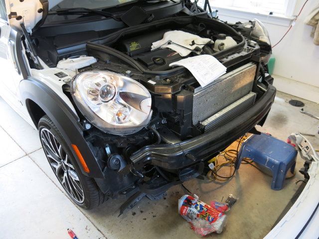
One of the other things I was trying to figure out ahead of time was whether I should bite the bullet and remove the front bumper or try to reach through the wheel well. Im just going to remove the front bumper although I am afraid I'll scratch the paint while handling....may wind up attaching some foam sheeting (the kind they ship electronics with) to the bumper exterior with painters non-marring masking tape in case I accidentally bump or scrape it against the concrete floor of my garage.
One of the other things I was trying to figure out ahead of time was whether I should bite the bullet and remove the front bumper or try to reach through the wheel well. Im just going to remove the front bumper although I am afraid I'll scratch the paint while handling....may wind up attaching some foam sheeting (the kind they ship electronics with) to the bumper exterior with painters non-marring masking tape in case I accidentally bump or scrape it against the concrete floor of my garage.
Keep in mind that depending on where the LED were ordered from, there may be only a 1 year warranty on parts (or two years from some Mini dealers). For installation, I would highly recommend removing the front bumper. I tried working around it but I would have save hours by simply removing it first. In the end I removed the bumper and was able to fasten the wires properly. Not to mention the windshield fluid resovoir is in the way. I was glad I ordered a replacement plastic expanding rivets for the wheel well trim from ECS (their shipping costs are outragiously expensive! for a 99 cent part will cost just under $10 for shipping which essentially gets you to a similar dealership pricing), since once you punch out the center, it was difficult to locate the little plastic pin. Most of the other fasterers are torx screws and/or bolts.
Last edited by komet155; Aug 15, 2014 at 09:10 AM.
4th Gear
Joined: Feb 2012
Posts: 399
Likes: 0
From: Exit 9
I was just browsing around on http://thebmwminipartstore.com/ and noticed that they offer a small parts flat rate shipping for $6.45 -anything that can fit in a 12x12x5-1/2 box. That will come in handy when I order some more small part soon....touch up paint, wheel center caps, etc.
4th Gear
Joined: Jun 2013
Posts: 519
Likes: 13
From: Charlottesville, VA
I was just browsing around on http://thebmwminipartstore.com/ and noticed that they offer a small parts flat rate shipping for $6.45 -anything that can fit in a 12x12x5-1/2 box. That will come in handy when I order some more small part soon....touch up paint, wheel center caps, etc.
4th Gear
Joined: Feb 2012
Posts: 399
Likes: 0
From: Exit 9
UPDATE: My alternative CU placement project is proceeding...slowly. Today I finally mounted the control box in that new location. It fits like a glove. I ran the blue wire across the cowl area to the waterproof grommet and ran it through under the dashboard. For now it's stashed inside the plastic footwell trim. I connected the hot wire to the accessory post on the positive battery terminal. It also fits there perfectly. I've temporarily pulled the in-line fuse since I'm not ready to have power to the C.U. yet. I connected the ground wire to the ground terminal, sandwiched in the space the bolt runs through.
For now, I've tucked away the cables that will run to the lighting units because I'm not about to remove the bumper today and deal with all of that.
I have already drilled a round notch in the upper edge of the bulkhead at the bend near the battery so I can run the cables neatly through there.
So, now the CU is neatly mounted. All I have to do is remove my front bumper, attach the new lights, run the cables forward along the right side of the car, attaching to existing cables, then across to the light on the left side.
Then, I have to make that connection for the one blue wire at the footwell unit, but I may first mount up my JCW gauges so I can access the FCU for both connections at the same time.
Bulkhead upright piece I trimmed. The red outline shows the part cut out in order to get the CU to fit up against the flat portion:

Diagram showing the upright piece position as well as where I cut the round notch for the main cable to come through:

This shows the prepared upright piece....ready to accept the C.U. Note there's some additional plastic trimmed, the pointy piece remaining wasnt going to do me any good. Make sure you install this before attaching the C.U. It's much easier that way:

Prefitting the CU to make sure it will fit neatly:

The CU in place under the cowl:

Hot wire fits under the nut on this battery terminal:

Negative wire ring terminal sandwiched in the squeeze area on the terminal. It fits around the bolt that goes through there:

Blue wire routed down under upright to go across cowl area:

This is only a supplement to other extensive write-ups for the full install to show this alternate placement. You may want to refer to other posts to see how to remove the watertight seal cover, etc.
Marked for cutting out the bulkhead notch:

One hole cut here:

The other right behind it to enable the cowl cover to fit and seal properly:

Test fitting of the cable running through bulkhead. Nice & neat, just the way I like it:

You can view the entire gallery here, including how I cut the hole using a step drill bit:
http://s875.photobucket.com/user/komet155/library/
Hope this helps!
I did some exploratory surgery today to see where I can neatly fit the control unit (since taping or zip tying it to the fuse box doesnt look right to me) and, after figuring out how to remove the wiper arms and cowl (good practice since I'm sure there will be several times I'll have to do this) I looked around under the cowl to see where I can stow the box and still run the wires where they need to go.
My first instinct was to check for room under the wiper linkage which required removal of the whole assembly (more practice). Unfortunately, there's not enough room to fit and neatly secure the box there.
Well, at least I can say I have experience removing my wiper linkage assembly.
So, I looked over near the battery side and found an upright plastic piece just to the right of the battery under the cowl (part # 51712755865).
Number 6 on this diagram:
http://www.realoem.com/bmw/showparts...51&fg=75&hl=15
I tried to place it against that but there is a slope towards the bottom which prevented it from fitting up against the flat part of this piece. I removed the piece and started cutting a slot through this slope with my dremel. It came out a little sloppy since I was "in the groove" but it will allow me to secure it there. The wiring branches that go to the lights would have to come through the cowl (easily done by cutting a small notch in the upper edge of the cowl with the weatherstrip removed) and will still reach. As for the other 3 wires, the 2 that need to go to the fuse box will have to be lengthened a foot since the box will be closer to right side of the car. I thought about this and figured if I used a few posi-lock weathertite connectors I can add some length AND only need to drill a small hole for a grommet in the left side of the cowl to pass wires through since the wire will be cut (dont need to pass the whole spade lug connectors through).
OH, and I'll probably order a new piece #51712755865 just so I can cut more neatly and carefully. I have issues.
So, basically, all you'd see are some wires neatly exiting the cowl. Easy Beezy! Time for a beer (Sierra Nevada Ruthless Rye).
Last edited by komet155; Aug 17, 2014 at 12:26 PM.
4th Gear
Joined: Jun 2013
Posts: 519
Likes: 13
From: Charlottesville, VA
UPDATE: My alternative CU placement project is proceeding...slowly. Today I finally mounted the control box in that new location. It fits like a glove. I ran the blue wire across the cowl area to the waterproof grommet and ran it through under the dashboard. For now it's stashed inside the plastic footwell trim. I connected the hot wire to the accessory post on the positive battery terminal. It also fits there perfectly. I've temporarily pulled the in-line fuse since I'm not ready to have power to the C.U. yet. I connected the ground wire to the ground terminal, sandwiched in the space the bolt runs through.
For now, I've tucked away the cables that will run to the lighting units because I'm not about to remove the bumper today and deal with all of that.
I have already drilled a round notch in the upper edge of the bulkhead at the bend near the battery so I can run the cables neatly through there.
So, now the CU is neatly mounted. All I have to do is remove my front bumper, attach the new lights, run the cables forward along the right side of the car, attaching to existing cables, then across to the light on the left side.
Then, I have to make that connection for the one blue wire at the footwell unit, but I may first mount up my JCW gauges so I can access the FCU for both connections at the same time.
Bulkhead upright piece I trimmed. The red outline shows the part cut out in order to get the CU to fit up against the flat portion:
Diagram showing the upright piece position as well as where I cut the round notch for the main cable to come through:
This shows the prepared upright piece....ready to accept the C.U. Note there's some additional plastic trimmed, the pointy piece remaining wasnt going to do me any good. Make sure you install this before attaching the C.U. It's much easier that way:
Prefitting the CU to make sure it will fit neatly:
The CU in place under the cowl:
Hot wire fits under the nut on this battery terminal:
Negative wire ring terminal sandwiched in the squeeze area on the terminal. It fits around the bolt that goes through there:
Blue wire routed down under upright to go across cowl area:
This is only a supplement to other extensive write-ups for the full install to show this alternate placement. You may want to refer to other posts to see how to remove the watertight seal cover, etc.
Marked for cutting out the bulkhead notch:
One hole cut here:
The other right behind it to enable the cowl cover to fit and seal properly:
Test fitting of the cable running through bulkhead. Nice & neat, just the way I like it:
You can view the entire gallery here, including how I cut the hole using a step drill bit:
http://s875.photobucket.com/user/komet155/library/
Hope this helps!
4th Gear
Joined: Feb 2012
Posts: 399
Likes: 0
From: Exit 9
Yes, I know that the official instructions call for grounding it there but since I've chosen to mount the control unit under the cowl (close to the battery) instead, I've looked for alternate positive and negative connections. Hot will be on the accessory post which is part of the terminal assembly and ground will be on the battery negative terminal UNLESS I can find another convenient ground post close by. I haven't looked very hard for one because I thought going directly to the battery would be OK.

5th Gear
Joined: Jul 2012
Posts: 777
Likes: 1
From: Richardson, TX
Yes, I know that the official instructions call for grounding it there but since I've chosen to mount the control unit under the cowl (close to the battery) instead, I've looked for alternate positive and negative connections. Hot will be on the accessory post which is part of the terminal assembly and ground will be on the battery negative terminal UNLESS I can find another convenient ground post close by. I haven't looked very hard for one because I thought going directly to the battery would be OK.
The reason for my response was from what you had said about staying away from multiple grounds on a single point (as I understood) which is what the original instructed ground point is. There is a lot of grounds on that post.