
Drivetrain My build. Teaser photos and updates

3rd Gear
Joined: Dec 2013
Posts: 253
Likes: 0
So how is the tuning of your monster motor going? Inquiring minds wanna know! I have 19,000 subscribers on my Blackberry Channel Blog ("Mini Cooper Gearheads") that are dying to know 2 things...how fast and how many horsepower?
Last edited by Gearheadaddy; Sep 27, 2014 at 01:49 AM.

Thread Starter
|
5th Gear
Joined: Aug 2008
Posts: 1,100
Likes: 13
From: Inman, SC
well its not running.. again. haha!
I cranked the car and ran it, but there ended up being a machining error on the new compressor housing. Just enough so that when the compressor wheel heated up it kissed the housing.
Turbo is in California now being repaired under warranty.
In the mean time I am upgrading the water cooling system (again)
After taking the car back apart this time I realized I hate the hoses running to and from the front bumper for the A2W set up. It's just a PITA every time you have to do anything.
So it is going in the rear!
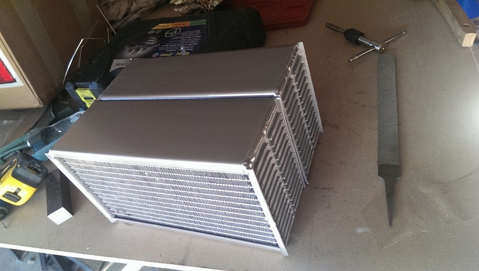
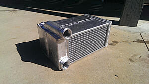
Taking out one of the muffler sections (driver side) and stacking two 3.25" thick, 6" tall, 10 " wide radiators back to front.
Water will flow in the back one, out, into the front one, and then back to the supply tank.
This gives it a cross flow countercurrent setup.
Basically cooler air hitting the front radiator cools off the already partially cooled water and the warmer air entering the second cools off the hotter water. This just improves heat transfer efficiency (vs having a single 6.5" thick core)
Will have a 10" auxiliary fan to help things out.
And using a tweaked and uprated Steward EMP water pump for the flow.
1" inlets and outlets.
-12 AN lines to the intercooler itself.
This pump will do 10gpm at 22 psi of back pressure (kinda nuts)
This well help out with a few things.
Coolant flow I need to be able to make sure everything in the engine bay stays happy.
Radiator setup has 2.8x the heat transfer surface of the front mounted setup (and is more efficient)
and it removes the heat from the engine bay and puts it in the rear of the vehicle, allowing the radiator to do a better job with cooling the engine.
That is all for now!
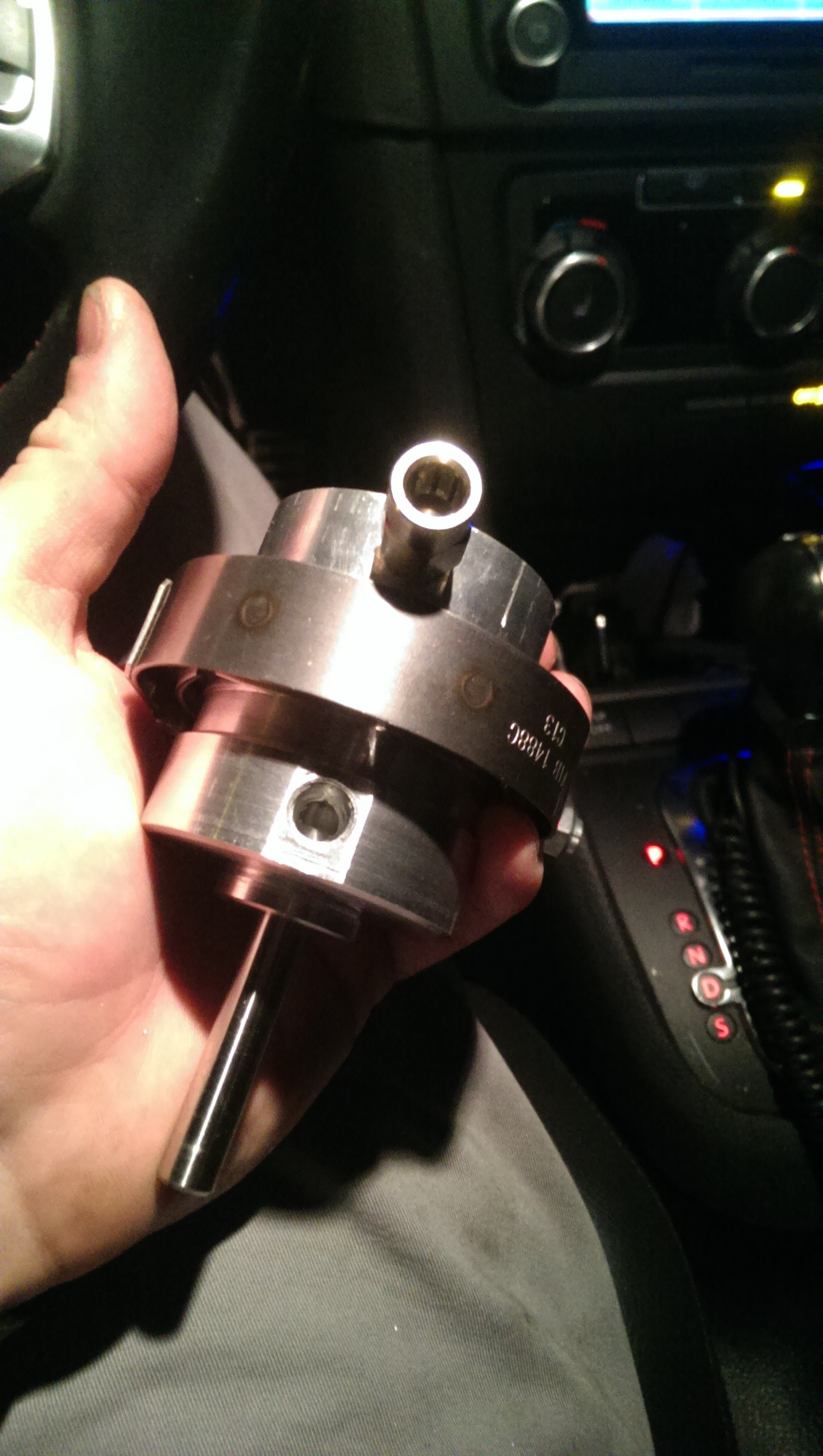
but I guess I can show you the crank from a month or two ago.
(still has some idle surge, but the super charger is loud. haha! what happens when the bypass is just a dump valve)
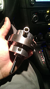
other excuses for delays : have designed my own diaphram style actuator and am in the works of putting it into a micro production run. Will be able to actuate any number of valves for use in boost or vacuum operation with no breakaway psi and fully adjustable and easily serviceable.
Traveling a lot for work : been on flights more in the past two months than I ever have before (new project at work) Travel at least every other week.
Building a partitioning gate for the local humane society as a charitable donation.
(needed to be chemically resistant and corrosion resistant as it gets washed down with hydrogen peroxide on a regular basis (kills PARVO) )
album -> http://imgur.com/a/IdBqN
teaser:

I cranked the car and ran it, but there ended up being a machining error on the new compressor housing. Just enough so that when the compressor wheel heated up it kissed the housing.
Turbo is in California now being repaired under warranty.
In the mean time I am upgrading the water cooling system (again)
After taking the car back apart this time I realized I hate the hoses running to and from the front bumper for the A2W set up. It's just a PITA every time you have to do anything.
So it is going in the rear!
Taking out one of the muffler sections (driver side) and stacking two 3.25" thick, 6" tall, 10 " wide radiators back to front.
Water will flow in the back one, out, into the front one, and then back to the supply tank.
This gives it a cross flow countercurrent setup.
Basically cooler air hitting the front radiator cools off the already partially cooled water and the warmer air entering the second cools off the hotter water. This just improves heat transfer efficiency (vs having a single 6.5" thick core)
Will have a 10" auxiliary fan to help things out.
And using a tweaked and uprated Steward EMP water pump for the flow.
1" inlets and outlets.
-12 AN lines to the intercooler itself.
This pump will do 10gpm at 22 psi of back pressure (kinda nuts)
This well help out with a few things.
Coolant flow I need to be able to make sure everything in the engine bay stays happy.
Radiator setup has 2.8x the heat transfer surface of the front mounted setup (and is more efficient)
and it removes the heat from the engine bay and puts it in the rear of the vehicle, allowing the radiator to do a better job with cooling the engine.
That is all for now!
but I guess I can show you the crank from a month or two ago.
(still has some idle surge, but the super charger is loud. haha! what happens when the bypass is just a dump valve)
other excuses for delays : have designed my own diaphram style actuator and am in the works of putting it into a micro production run. Will be able to actuate any number of valves for use in boost or vacuum operation with no breakaway psi and fully adjustable and easily serviceable.
Traveling a lot for work : been on flights more in the past two months than I ever have before (new project at work) Travel at least every other week.
Building a partitioning gate for the local humane society as a charitable donation.
(needed to be chemically resistant and corrosion resistant as it gets washed down with hydrogen peroxide on a regular basis (kills PARVO) )
album -> http://imgur.com/a/IdBqN
teaser:

1st Gear
Joined: Sep 2003
Posts: 35
Likes: 1
From: Portland, Or
Weird, I work with a physician (radiologist) who also was an aerispace engineer for Lockheed Martin. I think he used to work on scale prototype drone mockups of planes before they built the lifesize version.
Thread Starter
|
5th Gear
Joined: Aug 2008
Posts: 1,100
Likes: 13
From: Inman, SC
still a few more things to do.
This is from a few weeks ago.
Hopefully I will have time to start working on this again sometime soon, but I have been on more flights this month than I have been days at home.
This is from a few weeks ago.
Hopefully I will have time to start working on this again sometime soon, but I have been on more flights this month than I have been days at home.


3rd Gear
Joined: Dec 2013
Posts: 253
Likes: 0
Ideas
http://www.minimag.co.uk/2010/12/13/...r-performance/
Check out this little ride...may give you some good ideas...(for Hawthunk)
Check out this little ride...may give you some good ideas...(for Hawthunk)
Last edited by Gearheadaddy; Oct 28, 2014 at 10:47 PM.


3rd Gear
Joined: Jul 2014
Posts: 215
Likes: 2
I'm confused, are you routing the S/C vac line to the turbo so that the S/c gets bypassed when the turbo spools up? None of the builds I've seen seem to mention that, but it seems like the most efficient setup to me. BTW, have you got any Dyno runs yet? I'm hella curios. PS, your fab skills make Jan of RMW's BS projects, look like the amateur **** they really are. Bad *** bro
Thread Starter
|
5th Gear
Joined: Aug 2008
Posts: 1,100
Likes: 13
From: Inman, SC
(that I found)
-> bonus, it eliminates vacuum leaks playing a roll at idle / if something on the compressor side fails the car can still be driven.
but to answer your question, sort of. I am using the factory BPV, just in a new location. Hooks from before the intercooler, to the mid-pipe between the turbo and the supercharger.
Once the midpipe begins to see a positive pressure, this means that the turbo is now matching / exceeding the standard non-compounded, rate of the supercharger. At this point if the SC outlet is bled off into the mid pipe, there should not be a large drop in intake manifold pressure, but perhaps a small dip or a flat spot.
This dip of flat spot will affect the torque curve short term, but will be partially offset as it is reducing the load on the crank from the pulley side as the SC is now only using power to move its bearings and rotors and the water pump, but is using no (noteworthy) additional energy to compress gas as the ratio across the supercharger is 1:1. (it is still flowing a higher volumetric rate than the turbo, but the difference in the rates is simply re-circulated back through the bpv and into the SC inlet)
once the valve coefficient becomes a hindrance to the bleed-off air, then the intake manifold may see a slightly higher pressure than the turbo mid-pipe, but it should still be more efficient than a completely compounded setup.
Sorry for the lack of updates, car has not gotten a lot of work either.
Been traveling a TON for work recently and when I am home I have been focusing more on my social life and projects for other people (which help fund this madness) and the car has been sitting on the back burner.
Also currently waiting on my new welder to show up. (sold the diversion 180 as I out-grew its capabilities)
Hopefully sometime next week I will be the proud owner (officially) of a new HTP invertig 221 watercooled tig rig.
Will have pulse, AC balance, AC frequency and AC wave profile adjustability (plus a sh** ton more options)
Time to crank up that weld quality to 11!
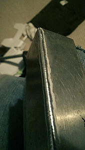
not that it was that bad before... (recent shot of some work I did on the gate) (now finished and installed)
316SS with .020 347 filler. 35 amps with a .040 tungsten (2% thoriated)

and then I have also been working on a custom actuator design that uses V-bands and has no break-away resistance... (diaphram)

3rd Gear
Joined: Dec 2013
Posts: 253
Likes: 0
Awesome Welds
You will love the ability to adjust on the new welder. Your welding is coming along beautifully!
No one has ever done that before on the mini for a twincharge that I was aware of, nor has anyone done the twincharge with the throttle on the intake manifold.
(that I found)
-> bonus, it eliminates vacuum leaks playing a roll at idle / if something on the compressor side fails the car can still be driven.
but to answer your question, sort of. I am using the factory BPV, just in a new location. Hooks from before the intercooler, to the mid-pipe between the turbo and the supercharger.
Once the midpipe begins to see a positive pressure, this means that the turbo is now matching / exceeding the standard non-compounded, rate of the supercharger. At this point if the SC outlet is bled off into the mid pipe, there should not be a large drop in intake manifold pressure, but perhaps a small dip or a flat spot.
This dip of flat spot will affect the torque curve short term, but will be partially offset as it is reducing the load on the crank from the pulley side as the SC is now only using power to move its bearings and rotors and the water pump, but is using no (noteworthy) additional energy to compress gas as the ratio across the supercharger is 1:1. (it is still flowing a higher volumetric rate than the turbo, but the difference in the rates is simply re-circulated back through the bpv and into the SC inlet)
once the valve coefficient becomes a hindrance to the bleed-off air, then the intake manifold may see a slightly higher pressure than the turbo mid-pipe, but it should still be more efficient than a completely compounded setup.
Sorry for the lack of updates, car has not gotten a lot of work either.
Been traveling a TON for work recently and when I am home I have been focusing more on my social life and projects for other people (which help fund this madness) and the car has been sitting on the back burner.
Also currently waiting on my new welder to show up. (sold the diversion 180 as I out-grew its capabilities)
Hopefully sometime next week I will be the proud owner (officially) of a new HTP invertig 221 watercooled tig rig.
Will have pulse, AC balance, AC frequency and AC wave profile adjustability (plus a sh** ton more options)
Time to crank up that weld quality to 11!
not that it was that bad before... (recent shot of some work I did on the gate) (now finished and installed)
316SS with .020 347 filler. 35 amps with a .040 tungsten (2% thoriated)

and then I have also been working on a custom actuator design that uses V-bands and has no break-away resistance... (diaphram)

(that I found)
-> bonus, it eliminates vacuum leaks playing a roll at idle / if something on the compressor side fails the car can still be driven.
but to answer your question, sort of. I am using the factory BPV, just in a new location. Hooks from before the intercooler, to the mid-pipe between the turbo and the supercharger.
Once the midpipe begins to see a positive pressure, this means that the turbo is now matching / exceeding the standard non-compounded, rate of the supercharger. At this point if the SC outlet is bled off into the mid pipe, there should not be a large drop in intake manifold pressure, but perhaps a small dip or a flat spot.
This dip of flat spot will affect the torque curve short term, but will be partially offset as it is reducing the load on the crank from the pulley side as the SC is now only using power to move its bearings and rotors and the water pump, but is using no (noteworthy) additional energy to compress gas as the ratio across the supercharger is 1:1. (it is still flowing a higher volumetric rate than the turbo, but the difference in the rates is simply re-circulated back through the bpv and into the SC inlet)
once the valve coefficient becomes a hindrance to the bleed-off air, then the intake manifold may see a slightly higher pressure than the turbo mid-pipe, but it should still be more efficient than a completely compounded setup.
Sorry for the lack of updates, car has not gotten a lot of work either.
Been traveling a TON for work recently and when I am home I have been focusing more on my social life and projects for other people (which help fund this madness) and the car has been sitting on the back burner.
Also currently waiting on my new welder to show up. (sold the diversion 180 as I out-grew its capabilities)
Hopefully sometime next week I will be the proud owner (officially) of a new HTP invertig 221 watercooled tig rig.
Will have pulse, AC balance, AC frequency and AC wave profile adjustability (plus a sh** ton more options)
Time to crank up that weld quality to 11!
not that it was that bad before... (recent shot of some work I did on the gate) (now finished and installed)
316SS with .020 347 filler. 35 amps with a .040 tungsten (2% thoriated)
and then I have also been working on a custom actuator design that uses V-bands and has no break-away resistance... (diaphram)
Thread Starter
|
5th Gear
Joined: Aug 2008
Posts: 1,100
Likes: 13
From: Inman, SC
okay, well the new welder is here!
New water pump (it's a beast) is here!
new water lines for the intercooler are here!
(1" ID.. LOL!)
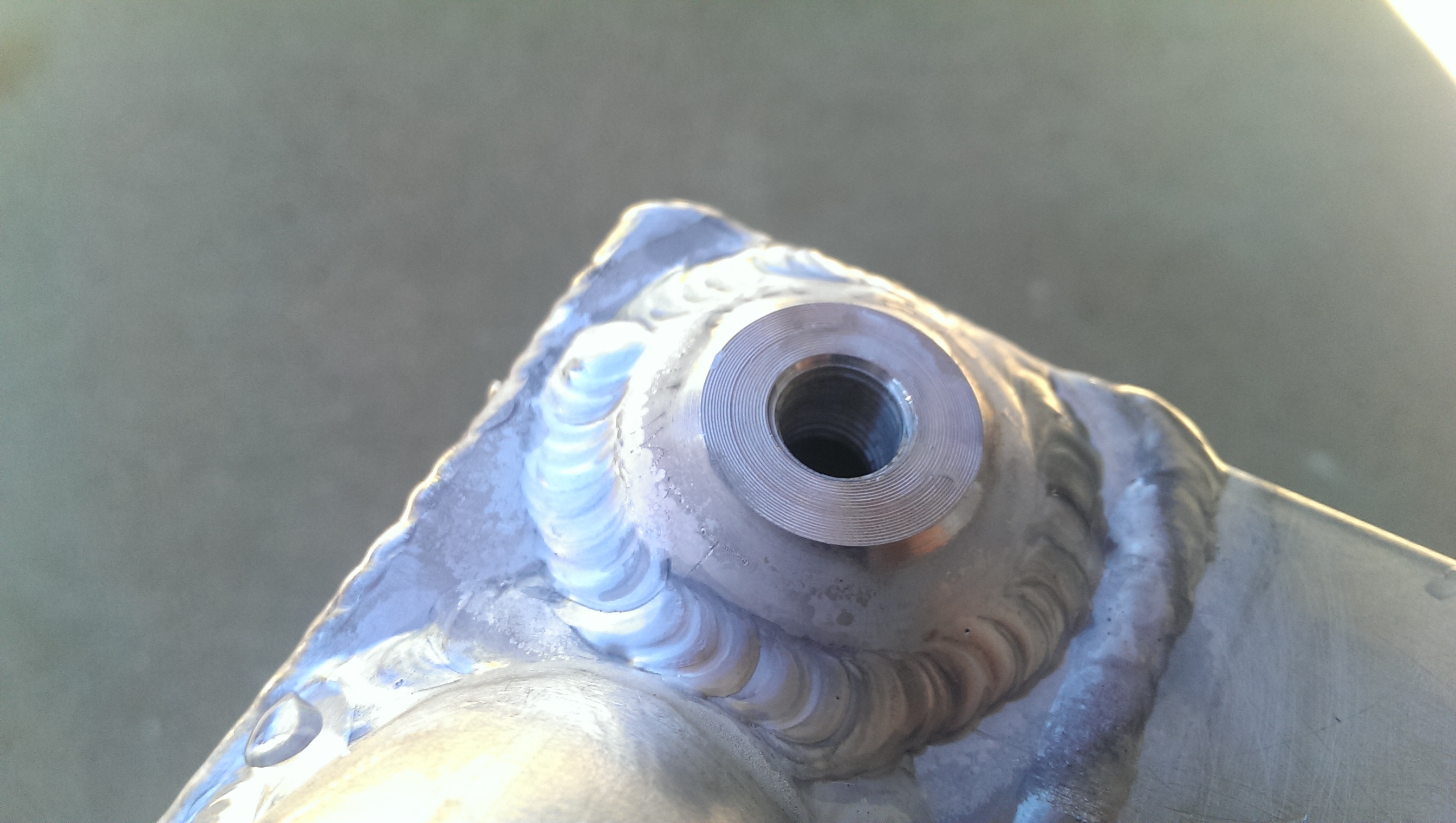
AN-16 fittings for the intercooler are here & in process of cutting off old fittings, boring out the holes, and putting new ones on.
Also working on those cylinders.. but making them by hand out of aluminum!
new welder!
 Partially funded by a few 2JZ turbo manifolds for some 1200HP GS300's (in progress)
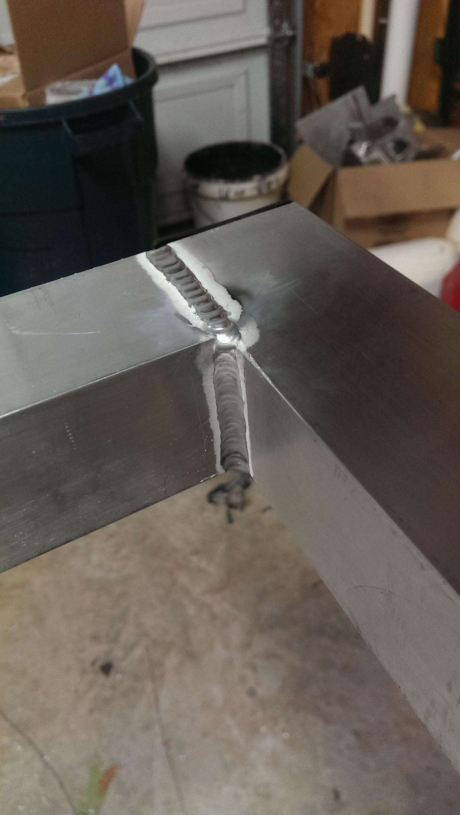
test weld with the above - .065 aluminum sheet, outside corner
On to the cylinders!
the blanks:
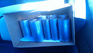
may be making a few...
had to custom grind a few tools to do some radius shapes etc. - 8% cobalt high speed steel

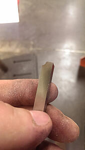
where they were used:

both halves done and assembled.
Absolutely NO valve stick. EVER!
Extremely fast action too. (low to no friction)
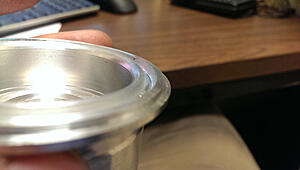
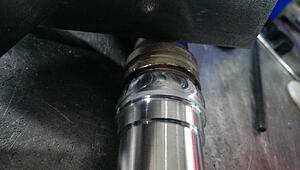
And lastly, the new water fittings (LOL!) (I have rather large hands as well...)

should work...
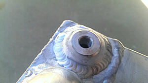
old ones off, everything ground back smooth (all done with a dremel tool... what a PITA) and new fittings welded on.
Crazy to see how much difference a better welder makes. All my old welds look like dog crap compared to the new ones I am running. (mostly due to arc focus and stability)
and a potato picture of the new fitting with the old one next to it.
Also note: the other fitting (for the other side) laying over the spark plug boot... and it's the same size as the top bit...
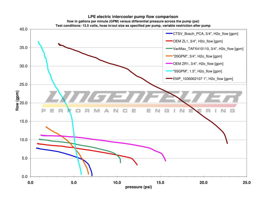
For those wondering "why?!" , well.. the new pump doesnt really care about pressure to be honest.
It will still flow 10GPM at 22 psi of back pressure.
Compare that to most intercooler pumps (the most common one is the bosch I was running) only does 5 GPM at ~6psi of back pressure.
(new one would do 30+ GPM at 6psi of back pressure!)
old- dark blue - far left.
new- well.. its the one on the... right... (brown)
Need? to support 400 hp through the intercooler I could fit in the car I need ~ 10gpm of cooling water... so why not build it to last?
New water pump (it's a beast) is here!
new water lines for the intercooler are here!
(1" ID.. LOL!)
AN-16 fittings for the intercooler are here & in process of cutting off old fittings, boring out the holes, and putting new ones on.
Also working on those cylinders.. but making them by hand out of aluminum!
new welder!
 Partially funded by a few 2JZ turbo manifolds for some 1200HP GS300's (in progress)
 test weld with the above - .065 aluminum sheet, outside corner

On to the cylinders!
the blanks:

may be making a few...
had to custom grind a few tools to do some radius shapes etc. - 8% cobalt high speed steel

where they were used:

both halves done and assembled.
Absolutely NO valve stick. EVER!
Extremely fast action too. (low to no friction)
And lastly, the new water fittings (LOL!) (I have rather large hands as well...)

should work...
old ones off, everything ground back smooth (all done with a dremel tool... what a PITA) and new fittings welded on.

Crazy to see how much difference a better welder makes. All my old welds look like dog crap compared to the new ones I am running. (mostly due to arc focus and stability)
and a potato picture of the new fitting with the old one next to it.

Also note: the other fitting (for the other side) laying over the spark plug boot... and it's the same size as the top bit...
For those wondering "why?!" , well.. the new pump doesnt really care about pressure to be honest.
It will still flow 10GPM at 22 psi of back pressure.
Compare that to most intercooler pumps (the most common one is the bosch I was running) only does 5 GPM at ~6psi of back pressure.
(new one would do 30+ GPM at 6psi of back pressure!)
old- dark blue - far left.
new- well.. its the one on the... right... (brown)
Need? to support 400 hp through the intercooler I could fit in the car I need ~ 10gpm of cooling water... so why not build it to last?
3rd Gear
Joined: Dec 2013
Posts: 253
Likes: 0
Fun!
You can clean up your previous welds on your Mini parts when you get used to all the new settings and capabilities of the new welder if you decide they don't meet your approval! The decision to look to the future will serve you well. Your Mini should rock!
okay, well the new welder is here!
New water pump (it's a beast) is here!
new water lines for the intercooler are here!
(1" ID.. LOL!)
AN-16 fittings for the intercooler are here & in process of cutting off old fittings, boring out the holes, and putting new ones on.
Also working on those cylinders.. but making them by hand out of aluminum!
new welder!
 Partially funded by a few 2JZ turbo manifolds for some 1200HP GS300's (in progress)
test weld with the above - .065 aluminum sheet, outside corner

On to the cylinders!
the blanks:

may be making a few...
had to custom grind a few tools to do some radius shapes etc. - 8% cobalt high speed steel


where they were used:


both halves done and assembled.
Absolutely NO valve stick. EVER!
Extremely fast action too. (low to no friction)

And lastly, the new water fittings (LOL!) (I have rather large hands as well...)

should work...
old ones off, everything ground back smooth (all done with a dremel tool... what a PITA) and new fittings welded on.

Crazy to see how much difference a better welder makes. All my old welds look like dog crap compared to the new ones I am running. (mostly due to arc focus and stability)
and a potato picture of the new fitting with the old one next to it.

Also note: the other fitting (for the other side) laying over the spark plug boot... and it's the same size as the top bit...
For those wondering "why?!" , well.. the new pump doesnt really care about pressure to be honest.
It will still flow 10GPM at 22 psi of back pressure.
Compare that to most intercooler pumps (the most common one is the bosch I was running) only does 5 GPM at ~6psi of back pressure.
(new one would do 30+ GPM at 6psi of back pressure!)

old- dark blue - far left.
new- well.. its the one on the... right... (brown)
Need? to support 400 hp through the intercooler I could fit in the car I need ~ 10gpm of cooling water... so why not build it to last?
New water pump (it's a beast) is here!
new water lines for the intercooler are here!
(1" ID.. LOL!)
AN-16 fittings for the intercooler are here & in process of cutting off old fittings, boring out the holes, and putting new ones on.
Also working on those cylinders.. but making them by hand out of aluminum!
new welder!
Partially funded by a few 2JZ turbo manifolds for some 1200HP GS300's (in progress) test weld with the above - .065 aluminum sheet, outside corner
On to the cylinders!
the blanks:
may be making a few...
had to custom grind a few tools to do some radius shapes etc. - 8% cobalt high speed steel
where they were used:
both halves done and assembled.
Absolutely NO valve stick. EVER!
Extremely fast action too. (low to no friction)
And lastly, the new water fittings (LOL!) (I have rather large hands as well...)
should work...
old ones off, everything ground back smooth (all done with a dremel tool... what a PITA) and new fittings welded on.
Crazy to see how much difference a better welder makes. All my old welds look like dog crap compared to the new ones I am running. (mostly due to arc focus and stability)
and a potato picture of the new fitting with the old one next to it.
Also note: the other fitting (for the other side) laying over the spark plug boot... and it's the same size as the top bit...
For those wondering "why?!" , well.. the new pump doesnt really care about pressure to be honest.
It will still flow 10GPM at 22 psi of back pressure.
Compare that to most intercooler pumps (the most common one is the bosch I was running) only does 5 GPM at ~6psi of back pressure.
(new one would do 30+ GPM at 6psi of back pressure!)
old- dark blue - far left.
new- well.. its the one on the... right... (brown)
Need? to support 400 hp through the intercooler I could fit in the car I need ~ 10gpm of cooling water... so why not build it to last?

4th Gear
Joined: Jan 2013
Posts: 500
Likes: 1
From: Lake Worth, Florida
You're going to build your own pistons? wtf...
Also can people stop quoting all the same pictures the OP is posting? It's annoying to scroll through the thread and see the same pics 3 times. Thanks.
Also can people stop quoting all the same pictures the OP is posting? It's annoying to scroll through the thread and see the same pics 3 times. Thanks.
Thread Starter
|
5th Gear
Joined: Aug 2008
Posts: 1,100
Likes: 13
From: Inman, SC
Yup! already built one 
Couldnt find one to buy.
Requirements I had were
*easy to take apart and service
*low to no break-away friction
*low actuation PSI, but a moderate closing force. (determines cylinder bore)
*as compact as possible
*spring push, pneumatic pull (reverse of most spring return cylinders)
*handle vacuum
*handle hot &cold working environments without sticking
versatile mounting configurations possible.
In the end it ended up being the only way to get what I wanted and not pay through the nose for it.
Closest thing is a TiAL waste gate actuator, but they want a lot for it and it is still difficult to take apart (6 screws vs the vibrant v-band)
Mine actually has fewer parts (but not by much) but is very similar in concept to the TiAL style.
Give up a little bit of the seal on the bottom end and just run a reamed bore that is .0012" over the size of the rod, but it holds pressure well enough to work but adds almost no friction to the actuation of the cylinder.
Thread Starter
|
5th Gear
Joined: Aug 2008
Posts: 1,100
Likes: 13
From: Inman, SC
Stupid forum has deleted this post three times now, so abridged version because it is annoying me today
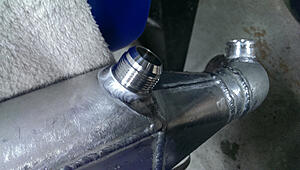
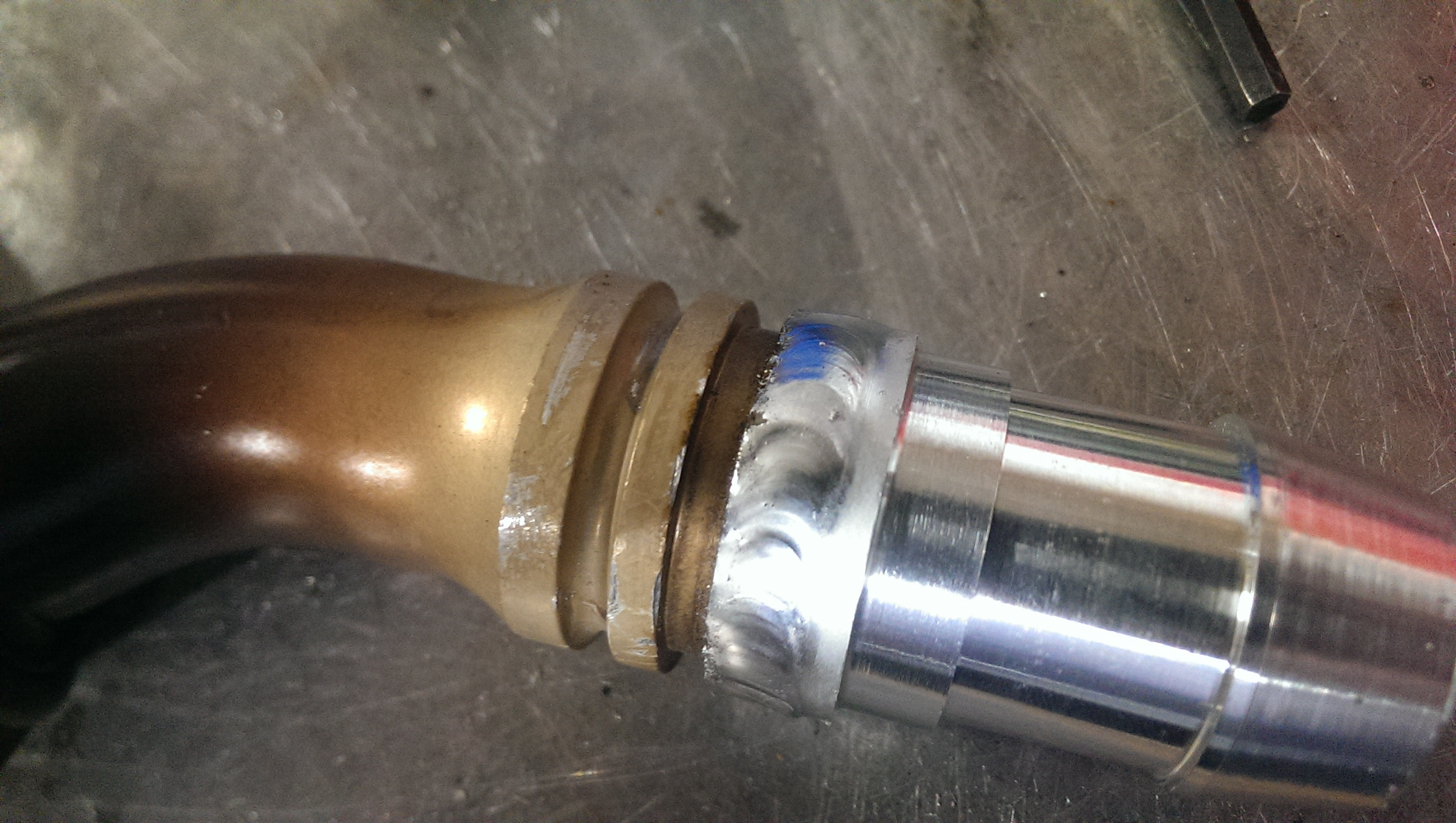
Had to cut up some AN fittings. They are -16 (1" OD) but my vibrant water line is 1" ID (fitting size on the pump I am using)
So I dissected my fittings, turned new barb fittings on the correct size, and welded them on!
Dissected:

new fitting turned and test fit. Left a .040" wide open gap on the seat of the new bit to allow for a welding channel

Welded!
Finish may have been slightly effected by the heat and UV from welding...

Okay, as to part (the main really.. other than work travel) reason for the recent massive lul in progress has been to a mental block in willingness to touch the car.
I was under a bit of pressure from a new position at work and things were going well with the car. It was a good way to vent, but then it bit back. Hard.
First the new turbo had a machining error. No biggie, sent it back to COMP and they took care of it.
While that was down I decided to re-do the intercooler and turbo coolant loop.
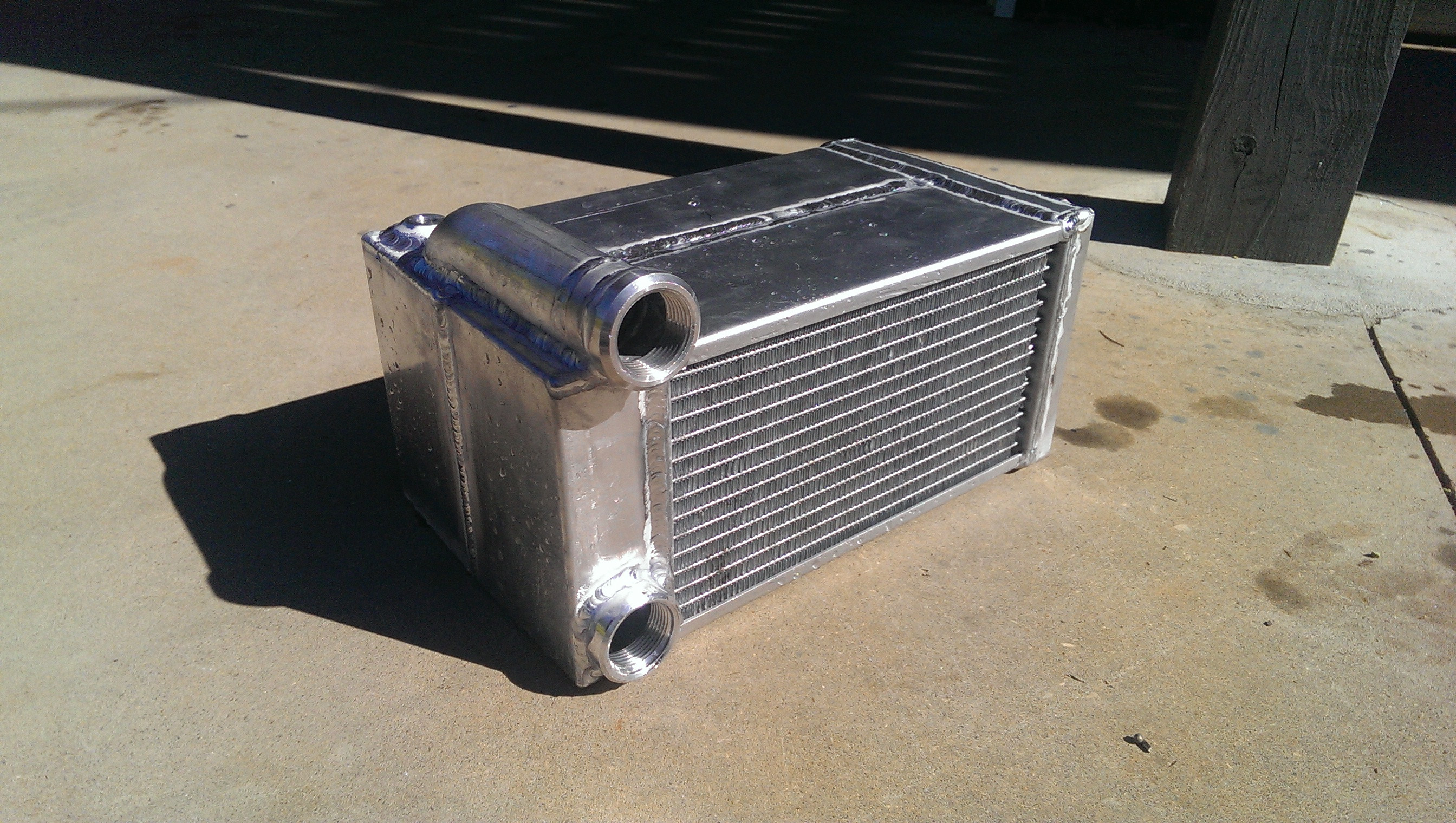
Remember those cores above?
Well I welded them together, designed up bend end tank ends. Clean, fewer welds, better looking.
Cut and broke them up (that means bent them for the non fabricators)
welded the end tanks, fittings, etc all on.
And it looked great! (for the diversion at least (old welder)
But then disaster. These cores are rather expensive (over $200 each) plus all of the time in the end tanks, fitting cost, prep time, welding, etc.
There was a leak. A pinhole. Only noticeable on a pressure gauge leak test. small but there.

I was PISSED!
To make things worse, it was on the vertical seam between the two end tanks. In the damn middle of the core. First weld I did, which meant everything had to come off if I was to have a hope of salvaging the cores.
cut the end tank off and could not find it. Checked all of the water passages to make sure I had not harmed any of the aluminum brazing.
All looked good.
re-ran some weld over the joint, hoping I could just fix it.
Welded up some new end tanks. Pressure tested. Still leaks.
So I cut the end tank back off. and got out a grinding bit set and some dye. Traced the pinhole to the corner.
The pinhole started at a weld overflow in a corner and made a horizontal turn and weld 3" towards the center of the core in under the weld bead and then went through to the outside. WTF?!
As it turns out the brazing process they used makes a super heavy oxide layer. Even though I cleaned and Cleaned I missed one little vein. Al2O3 has a much higher melting temp than aluminum, and this little stripe (we are talking .0001" wide probably) of higher temp material caused a passage.
Anywho, ground the entire weld out until I could see air between the two cores (open root) then cleaned the ever living crap out of the joint, pre-heated, and re-welded the center joint as an open root.
Slapped some end tanks back together and re-used the old end-tank top (as it was a bit complex and I didnt want to have to order another 1.25" bend etc etc.
Well, no more leak! only took me ~1.5 months to get around to fixing this. (many days I would come home and say "today I am going to work on that heat exchanger!" walk out to the garage turn on the light, see it, turn off the light and just go play with my dog out on the lake. )
but anywho, not as pretty anymore, but still better than I was expecting with how much I had to take it apart and put it back together, as well as with how little planning or layout I did when putting it back together (just cut pieces and slapped them together)
This was also with the old machine (diversion)
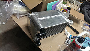
But it fits quite nicely under the trunk.
The 1.25" inlet tube runs between the battery box and the re-enforcement beam on the drivers side.
Had to cut up some AN fittings. They are -16 (1" OD) but my vibrant water line is 1" ID (fitting size on the pump I am using)
So I dissected my fittings, turned new barb fittings on the correct size, and welded them on!
Dissected:

new fitting turned and test fit. Left a .040" wide open gap on the seat of the new bit to allow for a welding channel

Welded!
Finish may have been slightly effected by the heat and UV from welding...

Okay, as to part (the main really.. other than work travel) reason for the recent massive lul in progress has been to a mental block in willingness to touch the car.
I was under a bit of pressure from a new position at work and things were going well with the car. It was a good way to vent, but then it bit back. Hard.
First the new turbo had a machining error. No biggie, sent it back to COMP and they took care of it.
While that was down I decided to re-do the intercooler and turbo coolant loop.
Remember those cores above?
Well I welded them together, designed up bend end tank ends. Clean, fewer welds, better looking.
Cut and broke them up (that means bent them for the non fabricators
)welded the end tanks, fittings, etc all on.
And it looked great! (for the diversion at least (old welder)
But then disaster. These cores are rather expensive (over $200 each) plus all of the time in the end tanks, fitting cost, prep time, welding, etc.
There was a leak. A pinhole. Only noticeable on a pressure gauge leak test. small but there.
I was PISSED!
To make things worse, it was on the vertical seam between the two end tanks. In the damn middle of the core. First weld I did, which meant everything had to come off if I was to have a hope of salvaging the cores.
cut the end tank off and could not find it. Checked all of the water passages to make sure I had not harmed any of the aluminum brazing.
All looked good.
re-ran some weld over the joint, hoping I could just fix it.
Welded up some new end tanks. Pressure tested. Still leaks.
So I cut the end tank back off. and got out a grinding bit set and some dye. Traced the pinhole to the corner.
The pinhole started at a weld overflow in a corner and made a horizontal turn and weld 3" towards the center of the core in under the weld bead and then went through to the outside. WTF?!
As it turns out the brazing process they used makes a super heavy oxide layer. Even though I cleaned and Cleaned I missed one little vein. Al2O3 has a much higher melting temp than aluminum, and this little stripe (we are talking .0001" wide probably) of higher temp material caused a passage.
Anywho, ground the entire weld out until I could see air between the two cores (open root) then cleaned the ever living crap out of the joint, pre-heated, and re-welded the center joint as an open root.
Slapped some end tanks back together and re-used the old end-tank top (as it was a bit complex and I didnt want to have to order another 1.25" bend etc etc.
Well, no more leak!
only took me ~1.5 months to get around to fixing this. (many days I would come home and say "today I am going to work on that heat exchanger!" walk out to the garage turn on the light, see it, turn off the light and just go play with my dog out on the lake. ) but anywho, not as pretty anymore, but still better than I was expecting with how much I had to take it apart and put it back together, as well as with how little planning or layout I did when putting it back together (just cut pieces and slapped them together)
This was also with the old machine (diversion)

But it fits quite nicely under the trunk.
The 1.25" inlet tube runs between the battery box and the re-enforcement beam on the drivers side.