
Drivetrain My build. Teaser photos and updates


Thread Starter
|
5th Gear
Joined: Aug 2008
Posts: 1,100
Likes: 13
From: Inman, SC
thanks for the kind words everyone!
working on sorting out a few issues.
Have a cycling idle that i cannot wrangle in, so i swapped out for the OEM throttle body (made an adapter plate) and it got a lot better, but not perfect.
Looking at re-making that inlet tube to be a lot shorter to cut down the throttle volume (may just be a hair too large for good throttle control)
Also on the list:
wire in a relay for the bosch water pump (w2a pump)
wire in EGT and oil press+ temp gauges (all innovate)
-> work on ordering necessary connectors / harnesses from mousser electronics to make it look all nice and tidy.
and then finally
-> clean up w2a lower lines (the ones running from / to the radiator) so that the bumper fits. I have the fittings as of today to do this, just need to get around to doing it.
for now, marvel in how quiet this thing is.
remember, all of the exhaust is straight through perf tube style mufflers and resonators
Last edited by soccerbummer1104; Jul 22, 2014 at 04:58 PM.


2nd Gear
Joined: Jul 2008
Posts: 65
Likes: 1
I just spent the last 3 hours reading through this, and i got to say, your welds improved a lot, and it's such a awesome build!
The last video didn't play for me :(. If I can make a request, can you post a video of the exhaust note w/ revs?
AWESOME!
The last video didn't play for me :(. If I can make a request, can you post a video of the exhaust note w/ revs?
AWESOME!
thanks for the kind words everyone!
working on sorting out a few issues.
Have a cycling idle that i cannot wrangle in, so i swapped out for the OEM throttle body (made an adapter plate) and it got a lot better, but not perfect.
Looking at re-making that inlet tube to be a lot shorter to cut down the throttle volume (may just be a hair too large for good throttle control)
Also on the list:
wire in a relay for the bosch water pump (w2a pump)
wire in EGT and oil press+ temp gauges (all innovate)
-> work on ordering necessary connectors / harnesses from mousser electronics to make it look all nice and tidy.
and then finally
-> clean up w2a lower lines (the ones running from / to the radiator) so that the bumper fits. I have the fittings as of today to do this, just need to get around to doing it.
for now, marvel in how quiet this thing is.
remember, all of the exhaust is straight through perf tube style mufflers and resonators
http://youtu.be/zrA7-t88-Mo
Thread Starter
|
5th Gear
Joined: Aug 2008
Posts: 1,100
Likes: 13
From: Inman, SC
as requested, vid.
I said it was quiet, and well,
I meant it.
Like really meant it.
note: yes my garage is currently quite messy.. busy busy.
2nd: this is with the larger throttle body. i have not changed ecu parameters for it yet, so it is reacting faster than it needs to (reacting as if it was a smaller valve) which is causing it to hunt for the idle, and is also why i have to softly de-rev it at the end (or else it would go straight past idle and hit the lower rpm limit and kill itself)
that is all...
currently swapped it back to the OEM throttle for round 1 of tuning (after i get things wired up. Hopefully this weekend sometime for the wiring, then scheduling time at DDM works to use their dyno and share brains)
updated the old post as well. LMK if these videos do not show up.
Hosted the ones prior to that last one via my computer, all these recent ones (from yesterday and today) have been directly from my phone.

Thread Starter
|
5th Gear
Joined: Aug 2008
Posts: 1,100
Likes: 13
From: Inman, SC
one more for the evening.
Spent most of today assembling a new work bench and tearing the garage apart, throwing crap out, and starting to clean a little.
but on a "break" I de-coupled the muffler section and took a video.
Not exactly what it would sound like in "loud" mode (not that loud) , but close enough.
(I plan on making a small straight pipe section so that I can unbolt and remove the muffler section and put a pipe in place to take it out the back)
Thread Starter
|
5th Gear
Joined: Aug 2008
Posts: 1,100
Likes: 13
From: Inman, SC
so, this post is a bit of a PSA. if someone wishes to add it to another thread, please feel free, as it may be a valuable resource to many.
Apparently there is a discrepency between the vipec's actual outputs and what the software knows them as.
As well as some play in how they are set up.
I started looking funny at my software when I went to go set up my aux 1 port,
Listed as on the expansion connector in the install manual and on the expansion loom,
as seen here:
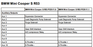
but instead found "ethrottle relay" in its place.
as seen here
As you can also see, aux 10 is completely missing, aux 9 is doing the aux 10 job and aux 4 is doing the aux 9 job..
WTF?!
I sent a quick email to Vi-Pec and as I waited for NZ to respond, I also dropped Jan a message.
Jan responded pretty quickly and got me on the right path, but I figured i'd post the transcription from the vi-pec tech support here directly (says the same thing Jan told me, but in a little more common language)
well.. thats not confusing at all Glad I asked ! 
but now you know...
Apparently there is a discrepency between the vipec's actual outputs and what the software knows them as.
As well as some play in how they are set up.
I started looking funny at my software when I went to go set up my aux 1 port,
Listed as on the expansion connector in the install manual and on the expansion loom,
as seen here:

but instead found "ethrottle relay" in its place.
as seen here
As you can also see, aux 10 is completely missing, aux 9 is doing the aux 10 job and aux 4 is doing the aux 9 job..
WTF?!
I sent a quick email to Vi-Pec and as I waited for NZ to respond, I also dropped Jan a message.
Jan responded pretty quickly and got me on the right path, but I figured i'd post the transcription from the vi-pec tech support here directly (says the same thing Jan told me, but in a little more common language)
Originally Posted by ViPEC Tech Support
Aux 1 does go to the expansion connector.
It is set as E throttle relay due to us needing an aux configured to allow E throttle to work correctly.
If you set AUX 7 or 8 as this function you will be able to use AUX 1 for the boost control. Should be no need for a relay the solenoid will be able to be controlled directly.
Aux 4 actually controls Aux 9 function and Aux 9 is controlling Aux 10 it due to an oddity in the firmware / hardware.
Glad I asked ! but now you know...

5th Gear
Joined: Sep 2002
Posts: 883
Likes: 2
Sleeper my @ss! If I heard that thing next to me I'd know right away something is up, and to be prepared to be embarrassed.
Thread Starter
|
5th Gear
Joined: Aug 2008
Posts: 1,100
Likes: 13
From: Inman, SC
well.. car is going back down.
On one hand,
YAY!! more parts to make!
and
YAY! going twincharged!
why?
Well I had the throttle pre-turbo. As designed.
It was stated that the comp turbo can handle a vacuum.
And it can.
*but* the turbulence caused by the throttle and short intake path does not allow for a rectifing zone for the flow to re-gain stability.
This means the flow maintains turbulence as it enters the turbine wheels which is causing an uneven loading on the compressor wheel (we think)
but the point of the matter is that it works. Works quite well.
But!
It makes a heck of a whirring sound and it makes me, my other engineering car buddies, and the engineers at comp all squirm, and not in a good way.
Good news is I knew something like this could happen, and had budgeted for it!
So new list of parts that are coming in.
4.5"x2.9"x8.5" bell w2a core. This will be going where the top mount for the SC was.
Synapse synchronic DV (diverter valve)
This will work as the "blow off" for the SC/turbo system
tubing to run it all together.
making a bolt-on adapter that will use an o-ring seat to seal to the front of the OE throttle body (no silicon boost coupler here!)
OE throttle is being re-located post supercharger on the entrance to the intake manifold!
(if I cant have weird turbo response from spooling in a vacuum, I will at least have some throttle response!)
new (to me) intake manifold is on its way for me to cut into / modify for ^^ and vacuum ports
re-locating a2w pump and resevoir to trunk of vehicle.
no interstage cooling. (bell core above is sized to work for this application just fine. it will be post SC )
Working on a method to best bypass SC when wanted (aka when the turbo kicks in)
- current thought is re-working an OE diverter valve to use a spring returned linear actuator that will open during boost. from the SC inlet.
that is all for now!
here is the whirr (i have done subsequent testing and shown that the bearings are fine, and it does not make this sound when not restricting the intake side of the turbine)
3rd Gear
Joined: Dec 2013
Posts: 253
Likes: 0
All the data you could collect from the OBDII and the Torque app would probably help if you could figure out how to hook it up...I just paid the $5 for the Torque Pro app. It's awesome...gonna dyno and keep all the data from both and start to chart it....hope you beefed up the bottom end...don't spit parts on the ground...makes a big mess and sounds horrible...
Thread Starter
|
5th Gear
Joined: Aug 2008
Posts: 1,100
Likes: 13
From: Inman, SC
@gearhead,
respectfully, I have a ViPEC standalone V series.
A. it tells me a lot more than an OBDII app will
B. it does not output a signal to OBDII port anyways, and thus the app will not work aside from the G-force meter.
but thank you.
respectfully, I have a ViPEC standalone V series.
A. it tells me a lot more than an OBDII app will
B. it does not output a signal to OBDII port anyways, and thus the app will not work aside from the G-force meter.
but thank you.


Thread Starter
|
5th Gear
Joined: Aug 2008
Posts: 1,100
Likes: 13
From: Inman, SC
Prepare for Boost!!!
well somewhat...
So,
How do we successfully mount piping to the throttle body if it will be seeing boost pressure?
Well, the typical way would be to use a sylicone coupling and worm-clamp the ever living crap out of it. no?
Well in what way is my build typical :haha: !
So, I started by removing the lip for retaining the factory inlet tube (keep things from backing off, it was interfeering with my design)
Then I had this nifty little adapter that I designed last night made by a local machinist who is interested in my build.
This is designed to rest over the inlet to the throttle and incorporate a square o-ring seal that will mate with the very top edge of the throttle body inlet.
This way as it gets bolted down it will compress the o-ring and create a seal!
O-ring seat lip is machined so that when not bolted, the bottom of the adapter will be .01" from fully seating (allows the o-ring to compress .010" for sealing)
The top of this adapter is also 2.5" OD with an .065" wall.
This will allow for easy welding to tubing or to a vanjen joint.
seated in place! (but not bolted down)

Working on the throttle body mounting flange now, then I need to go home and start cutting up the new R53 intake manifold I got from a junk yard in atlanta.
Happy Friday!
Last edited by soccerbummer1104; Aug 27, 2014 at 08:27 AM.


Thread Starter
|
5th Gear
Joined: Aug 2008
Posts: 1,100
Likes: 13
From: Inman, SC
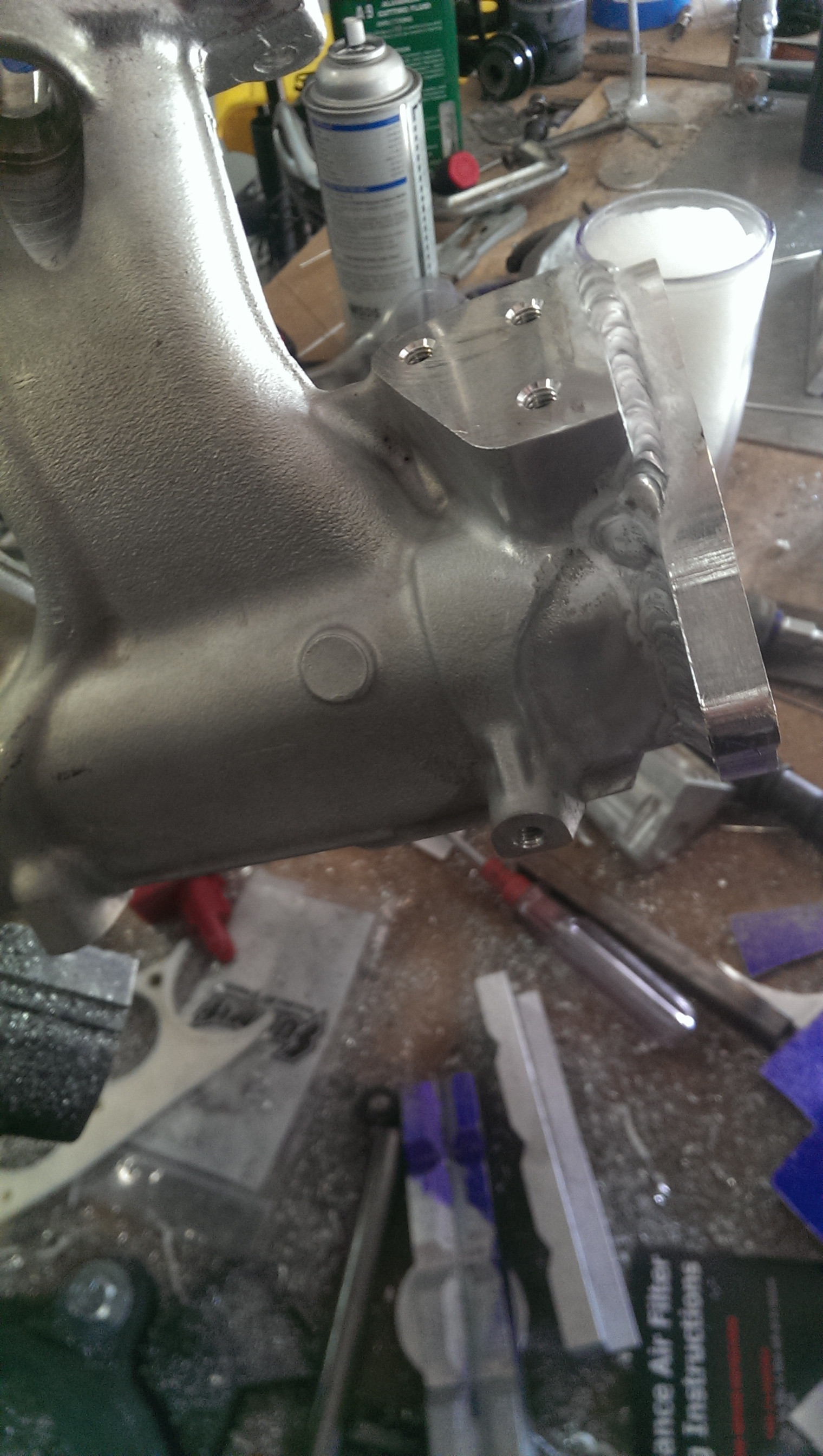
okay, so i mocked the manifold and new flange up, clocked, marked, and then welded the flange on

pardon the mess in the background. lots of stuff going on.

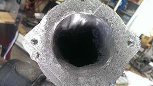
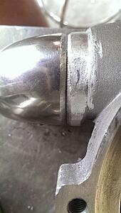
Then, if you scroll up a tad, you will notice that the old intake manifold that i cut the flange off of was not exactly what we would describe as round.
In fact, that profile would make a rather atrocious wheel.
but!
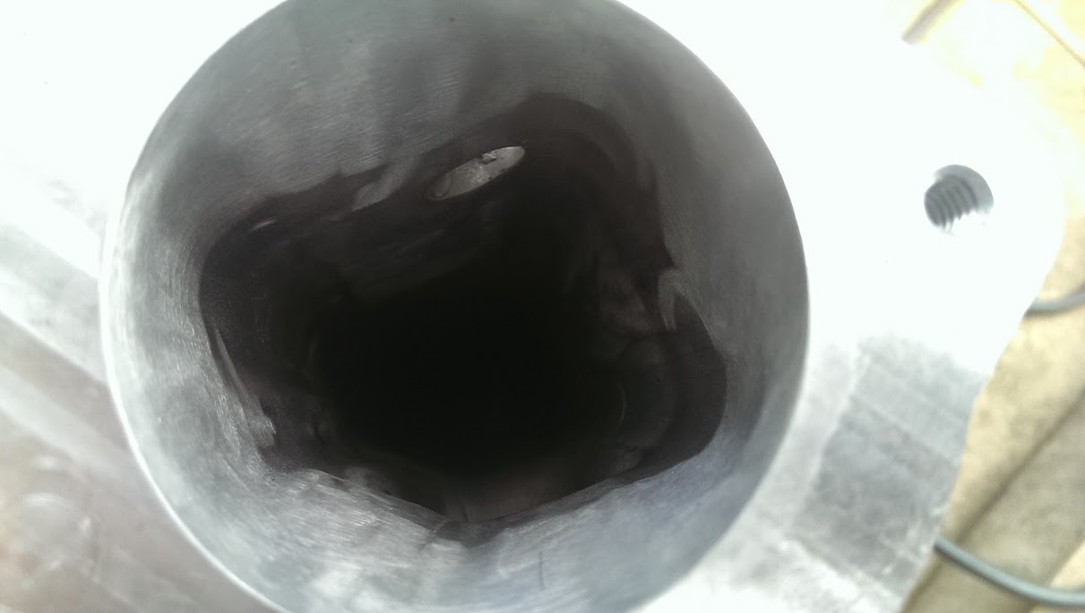
I decided to see if I could smooth things out, and it came out quite well

Welded the inside to add some metal and bridge the two profiles (a PITA considering the torch does not really fit in the opening for welding this)

Then i took a dremmel with a flapp disk and some aluminum cutting fluid to help lubricate the chips and extend the life of the disk a little bit and went to town on the weld bead at first and then smoothing the transition till I got it where i liked
(made a small mess)
cleaned up a tad

did a little touch up filing on the edge so as to allow for the use of the OE intercooler mount
and an ultra potato quality photo of the throttle assembly all bolted on!

(phones camera is great, but things get weird when it is back-lit)

pardon the mess in the background. lots of stuff going on.
Then, if you scroll up a tad, you will notice that the old intake manifold that i cut the flange off of was not exactly what we would describe as round.
In fact, that profile would make a rather atrocious wheel.
but!
I decided to see if I could smooth things out, and it came out quite well
Welded the inside to add some metal and bridge the two profiles (a PITA considering the torch does not really fit in the opening for welding this)

Then i took a dremmel with a flapp disk and some aluminum cutting fluid to help lubricate the chips and extend the life of the disk a little bit and went to town on the weld bead at first and then smoothing the transition till I got it where i liked
(made a small mess)

cleaned up a tad
did a little touch up filing on the edge so as to allow for the use of the OE intercooler mount
and an ultra potato quality photo of the throttle assembly all bolted on!
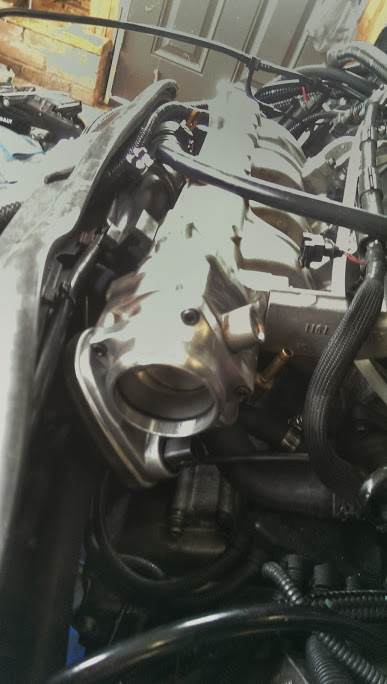
(phones camera is great, but things get weird when it is back-lit
)

Thread Starter
|
5th Gear
Joined: Aug 2008
Posts: 1,100
Likes: 13
From: Inman, SC
yay, a reply!
(lol!)
time for the weekend update:
I was a good and forgot to refill my argon cylinder, so no welding (and believe me, I kicked myself a few times)
but I had plenty of other things to do
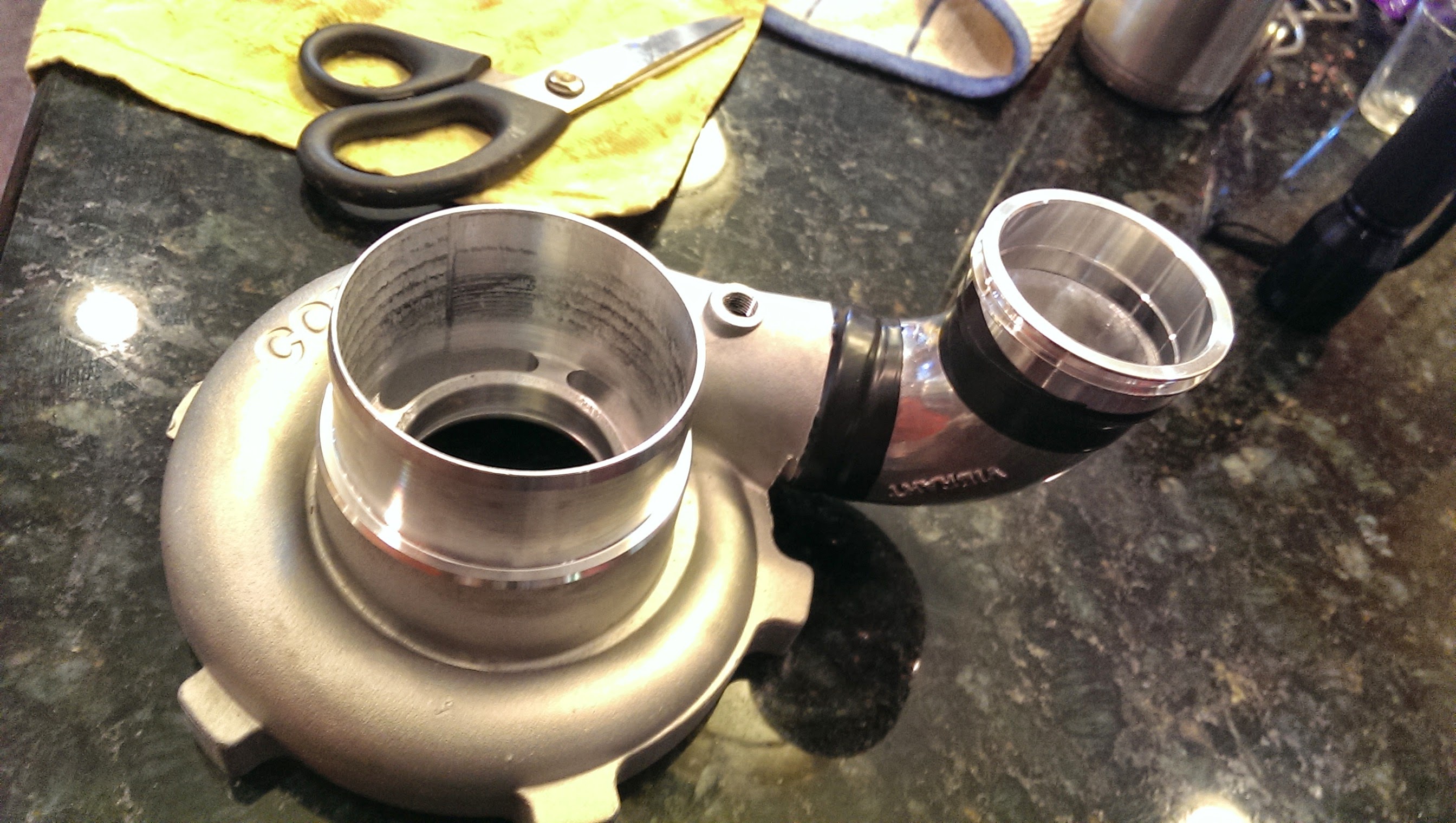
New compressor housing came in over the weekend,
So as per my usual self, I started drilling and cutting into it :P
This one is surge ported as well.
drilled a hole and tapped it for boost reference for the boost controller
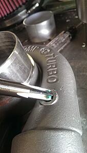

The green stuff is aluminum cutting fluid.
Without it the threads would not have come out so nicely in this soft casting (half would probably be missing)
Then I cut off the outlet, leaving enough of a stub for getting my welding torch in.
Ported the inside out to the right size, then I polished the inside (and outside) of a tight radius cast bend, cut a little bit of leg length off of it, chamfered the two ends, and it is ready for welding! (this is where i realized I was out of argon :( )
So since I couldnt work on that,
So, I re-worked the turbo inlet pipe

Tucks around everything nicely and allows for OE hookups for the coolant system and clears the radiator fan.
another shot

since I could not weld on the compressor housing I mocked it up and put it on the car

Still need to finish cutting the little end bits for the intercooler,
And I have hidden one pipe section as it is going to be for something super nifty.
But I have to test out some pneumatics to see if it works first before I show it off.
As well as a regulator, one way valve, and a return spring and a butterfly valve...
Fun fun
Hope the weekend is going well for everyone!
(lol!)
time for the weekend update:
I was a good and forgot to refill my argon cylinder, so no welding (and believe me, I kicked myself a few times)
but I had plenty of other things to do
New compressor housing came in over the weekend,
So as per my usual self, I started drilling and cutting into it :P
This one is surge ported as well.
drilled a hole and tapped it for boost reference for the boost controller


The green stuff is aluminum cutting fluid.
Without it the threads would not have come out so nicely in this soft casting (half would probably be missing)
Then I cut off the outlet, leaving enough of a stub for getting my welding torch in.
Ported the inside out to the right size, then I polished the inside (and outside) of a tight radius cast bend, cut a little bit of leg length off of it, chamfered the two ends, and it is ready for welding! (this is where i realized I was out of argon :( )

So since I couldnt work on that,
So, I re-worked the turbo inlet pipe
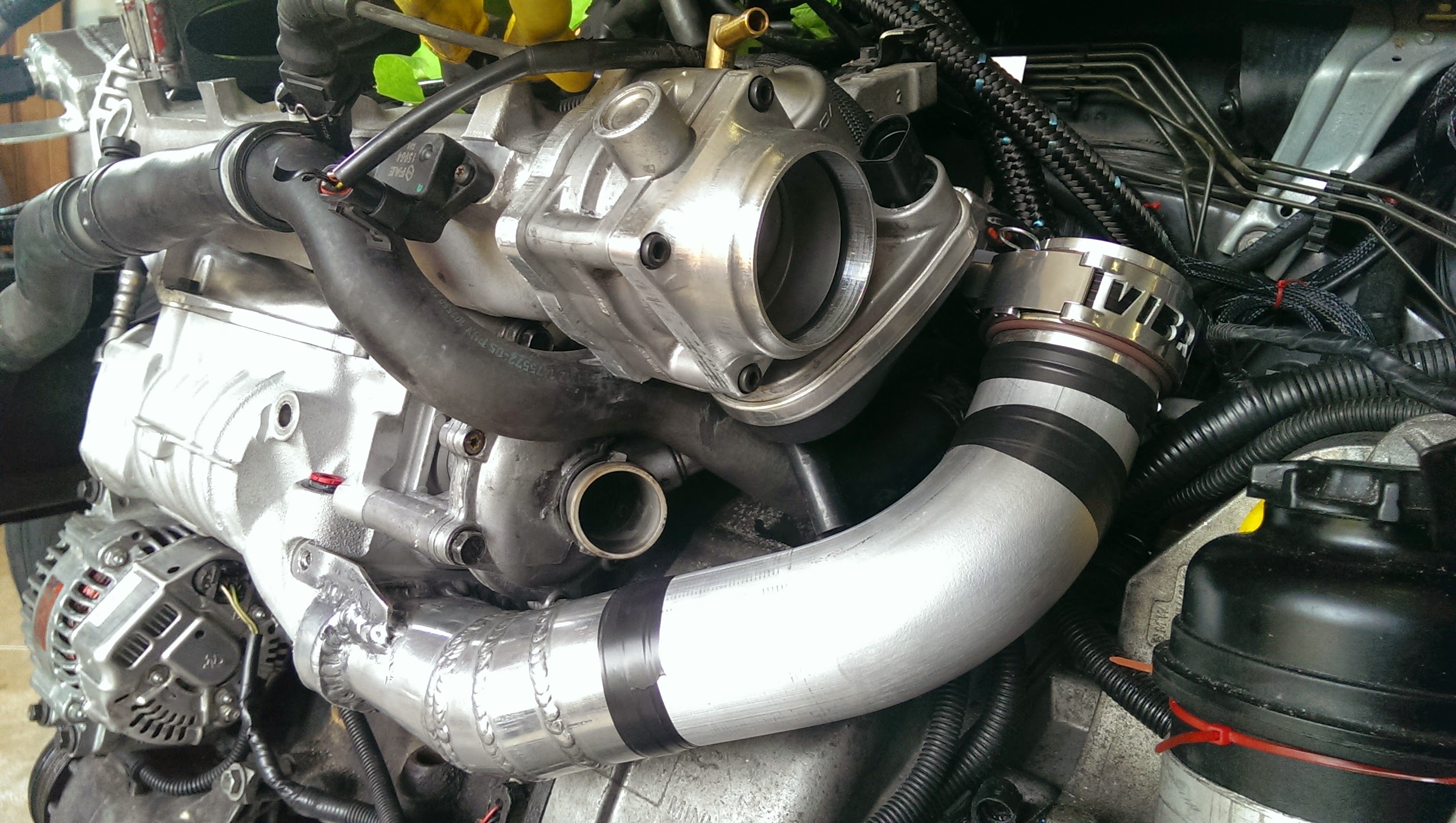
Tucks around everything nicely and allows for OE hookups for the coolant system and clears the radiator fan.
another shot

since I could not weld on the compressor housing I mocked it up and put it on the car
Still need to finish cutting the little end bits for the intercooler,
And I have hidden one pipe section as it is going to be for something super nifty.
But I have to test out some pneumatics to see if it works first before I show it off.
As well as a regulator, one way valve, and a return spring and a butterfly valve...
Fun fun
Hope the weekend is going well for everyone!
Last edited by soccerbummer1104; Aug 27, 2014 at 08:29 AM.
3rd Gear
Joined: Dec 2013
Posts: 253
Likes: 0
Nice job!!! Well thought out and well done (except for forgetting the Argon gas needed to purge the oxygen for a clean aluminum weld). Should sound different too!
And yes the weekend was awesome!...Made a checkered flag for my MINI antenna on Friday and won a $100 Visa gift Card at a Mini Breakfast put on by Irvine Mini in California on Saturday. Just had to be the FIRST one there flying the flag! Breakfast started at 8:30 a.m....I was there at 6:05 a.m.! Then today (Sunday) I took first place in a Cribbage Tournament in West Covina CA. Out of 49 players, qualified 5th in the qualifying round of 12 games and went all the way (4 rounds) in the elimination rounds of best 3 of 5 games there. Took a total of 26 games of Cribbage to get it done!!!
And yes the weekend was awesome!...Made a checkered flag for my MINI antenna on Friday and won a $100 Visa gift Card at a Mini Breakfast put on by Irvine Mini in California on Saturday. Just had to be the FIRST one there flying the flag! Breakfast started at 8:30 a.m....I was there at 6:05 a.m.! Then today (Sunday) I took first place in a Cribbage Tournament in West Covina CA. Out of 49 players, qualified 5th in the qualifying round of 12 games and went all the way (4 rounds) in the elimination rounds of best 3 of 5 games there. Took a total of 26 games of Cribbage to get it done!!!
Last edited by Gearheadaddy; Aug 10, 2014 at 11:03 PM.


