
Drivetrain My build. Teaser photos and updates


Thread Starter
|
5th Gear
Joined: Aug 2008
Posts: 1,100
Likes: 13
From: Inman, SC
first piece done!
only messed up one about an hour in, so I had to start over.
all the manual steps and other bits and making jigs etc took ~ 5-6 hours just for this one piece. O.O
worth it? worth it.
only messed up one about an hour in, so I had to start over.
all the manual steps and other bits and making jigs etc took ~ 5-6 hours just for this one piece. O.O
worth it? worth it.

Thread Starter
|
5th Gear
Joined: Aug 2008
Posts: 1,100
Likes: 13
From: Inman, SC
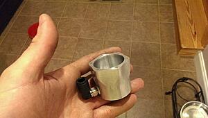
well, it works!
All that is left is to make the mount, trim the actuating bar, tap it as needed for threads etc, and make the bit that will attach to the stock BPV!
but lets be honest, you all just want pictures... you ******! (jk.. )
)
parts needed / I made.
all this started as raw material from mcmaster car (lip seal, o-ring, and rod bearing aside) and round metal bar stock.

assembled piston
https://i.imgur.com/RrrCj9E.jpg
this was made by turning down the shaft from .375 to .3125 for a 0.245" section. then drilling a .201" diameter hole in the center of the shaft and tapping it for 1/4 -20 threads.
I then took a 0.515" thick piece (rough cut) of 1.625" OD aluminum bar stock and turned it down to 1.483" OD and faced it to 0.499"
I drilled a 0.25" diameter hole through the middle and then used a 0.3125" Diameter end mill to touch off and "drill" 0.25" deep into that same hole.
I then flipped the piece and used a 0.375" mill to put a 0.125" deep hole in that side.
I then faced the second side to have the profiles for the o-ring seat and top hat.
Then I made a jig in the mill, centered the piece, and told it to drill the bolt holes.
The turned shaft went into the 0.3125x.25" deep hole and was pulled into a press fit by using a low profile 1/4-20 bolt.
Makes sure everything is nice and concentric.
where the shaft is pressed in

just tight enough!
There is only about a .004" compression on the O-ring in the cylinder bore and the o-ring groove height is 1.30" (.005" taller than the o-ring)
This allows the o-ring to switch profiled ever so slightly and fill the cavity when it is compressed, but does not let it move too much which causes sticking.

I did some figuring when I was ordering stuff for this, and the spring rate is about 0.5lbs too low and it needs more pre-load compression.
(it was a 7.8 lb 0.625" long spring for a 0.5" throw, so only 0.125" of pre-load)
So i have ordered a new spring that will be here tomorrow and should work well.
Current spring fully actuates at 5-6"hg, new one will just begin to actuate at 5-6" and be fully open by 10"
(8.4lb 1" long spring giving 0.5" of pre-load or 4.2lbs of spring pressure at rest)

All that is left is to make the mount, trim the actuating bar, tap it as needed for threads etc, and make the bit that will attach to the stock BPV!
but lets be honest, you all just want pictures... you ******! (jk..
) parts needed / I made.
all this started as raw material from mcmaster car (lip seal, o-ring, and rod bearing aside) and round metal bar stock.

assembled piston
https://i.imgur.com/RrrCj9E.jpg
this was made by turning down the shaft from .375 to .3125 for a 0.245" section. then drilling a .201" diameter hole in the center of the shaft and tapping it for 1/4 -20 threads.
I then took a 0.515" thick piece (rough cut) of 1.625" OD aluminum bar stock and turned it down to 1.483" OD and faced it to 0.499"
I drilled a 0.25" diameter hole through the middle and then used a 0.3125" Diameter end mill to touch off and "drill" 0.25" deep into that same hole.
I then flipped the piece and used a 0.375" mill to put a 0.125" deep hole in that side.
I then faced the second side to have the profiles for the o-ring seat and top hat.
Then I made a jig in the mill, centered the piece, and told it to drill the bolt holes.
The turned shaft went into the 0.3125x.25" deep hole and was pulled into a press fit by using a low profile 1/4-20 bolt.
Makes sure everything is nice and concentric.
where the shaft is pressed in

just tight enough!
There is only about a .004" compression on the O-ring in the cylinder bore and the o-ring groove height is 1.30" (.005" taller than the o-ring)
This allows the o-ring to switch profiled ever so slightly and fill the cavity when it is compressed, but does not let it move too much which causes sticking.

I did some figuring when I was ordering stuff for this, and the spring rate is about 0.5lbs too low and it needs more pre-load compression.
(it was a 7.8 lb 0.625" long spring for a 0.5" throw, so only 0.125" of pre-load)
So i have ordered a new spring that will be here tomorrow and should work well.
Current spring fully actuates at 5-6"hg, new one will just begin to actuate at 5-6" and be fully open by 10"
(8.4lb 1" long spring giving 0.5" of pre-load or 4.2lbs of spring pressure at rest)


5th Gear
Joined: Nov 2009
Posts: 771
Likes: 1
From: Port Orange, Florida
Are there different formulations of the white plastic pieces? I just wondered how you "machine" those pieces down to an exact size without melting off the edges. I presume everything moves very slowly when you are making those parts, correct? And, does the plastic expand at the same rate as the metal? How do you assure proper clearance to allow for that expansion?
Still loving every minute of this. You should sell tickets.
Still loving every minute of this. You should sell tickets.

6th Gear

Joined: Jan 2013
Posts: 2,257
Likes: 15
From: Dover, NH
depending on the plastic they machine very easilly, metal cutting tools going through plastic is fun, cause you can go as fast as you can and itll cut! so long as your no exceding the depth of the tool =)
nylon and abs are easily machnined
nylon and abs are easily machnined
5th Gear
Joined: Nov 2009
Posts: 771
Likes: 1
From: Port Orange, Florida
You guys know that I have been searching the net for small machine lathes now, don't you? Why is it that everything I do costs money? I just have to learn to do even just a tiny bit of this.
My last project was silver soldering a bicycle frame that I built in the late 70s. That bike is still hanging in my garage (the bike is fine, but its motor needs new gaskets or something).
My last project was silver soldering a bicycle frame that I built in the late 70s. That bike is still hanging in my garage (the bike is fine, but its motor needs new gaskets or something).
Thread Starter
|
5th Gear
Joined: Aug 2008
Posts: 1,100
Likes: 13
From: Inman, SC
material expansion rates do play a roll, but that is part of the point of the o-ring.
The o-ring compression at room temperature is only ~.003" which is enough to take up the play between the aluminum bore and the piston expanding and contracting during heating and cooling at the 20F-150F environment this piston should be seeing.
This is helped by the fact that these two materials are the same type of material and therefore should expand at roughly equal rates, differences coming from material thickness and profile alone.
The sprint loaded lip seal and bearing are made from PTFE and are also designed for the temperature range (actually from -40 to +450 F) for the seat and rod size I selected.
Rod is 6061 aluminum with a ceramic electroplated coating that is dimensionally accurate to .00003" iirc. (in diameter)
plastics are low temp and easily modified.
These should not expand or contract too much, but I am slighly concerned about there temperature windows.
Bonus of this material in the bore is that it is considerably softer than the aluminum and therefore if it does make contact, it will not scratch the bore.
Last edited by soccerbummer1104; Aug 27, 2014 at 08:31 AM.
6th Gear
Joined: Jan 2013
Posts: 2,257
Likes: 15
From: Dover, NH
You guys know that I have been searching the net for small machine lathes now, don't you? Why is it that everything I do costs money? I just have to learn to do even just a tiny bit of this.
My last project was silver soldering a bicycle frame that I built in the late 70s. That bike is still hanging in my garage (the bike is fine, but its motor needs new gaskets or something).
My last project was silver soldering a bicycle frame that I built in the late 70s. That bike is still hanging in my garage (the bike is fine, but its motor needs new gaskets or something).
good luck on your search, some can be had preety cheap!
Thread Starter
|
5th Gear
Joined: Aug 2008
Posts: 1,100
Likes: 13
From: Inman, SC
thought i dropped this over here last night.
hmm. oh well!
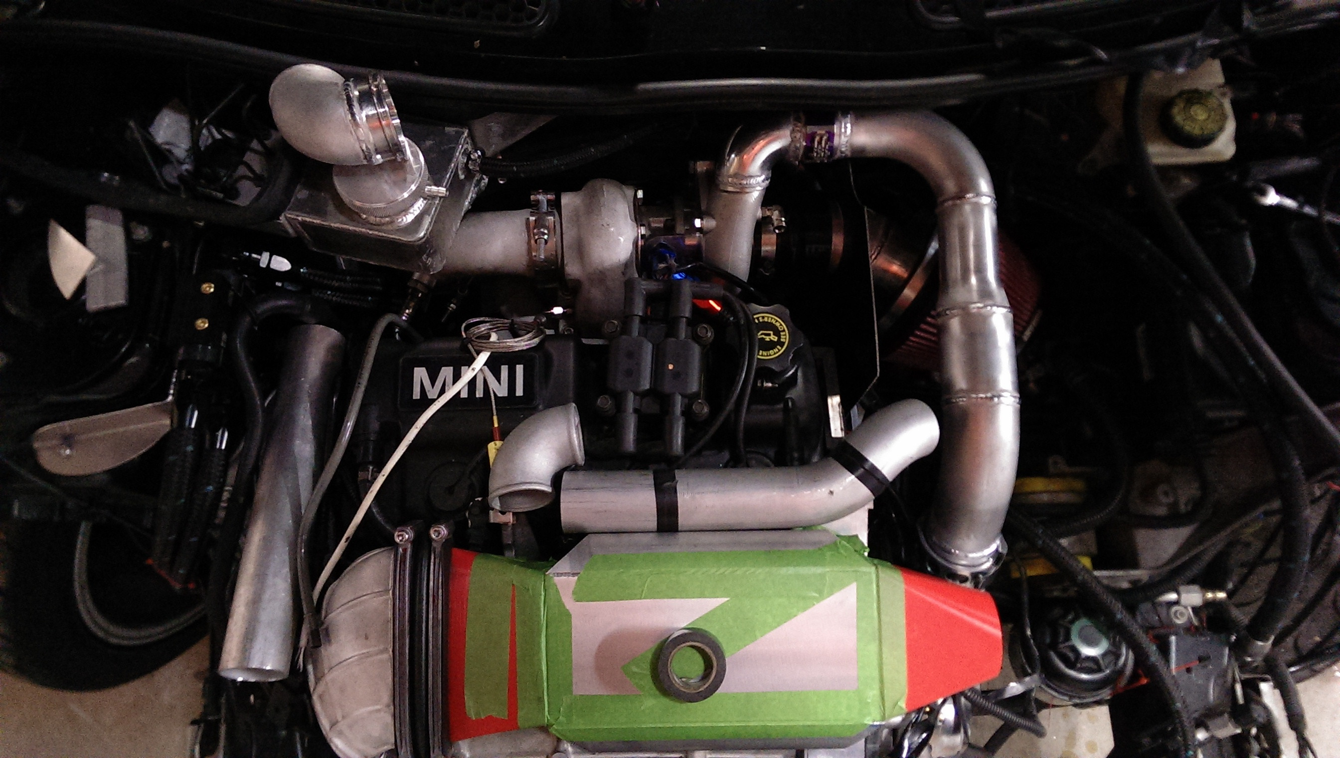
little welding update!
still have a few things to work out, and some bits from McMasterCarr are coming in on monday. (first round of parts I ordered for my turbo vs SC boost controller setup were a little undersized for my liking)
changed out the spring in the piston and now it works flawlessly.
Now i just need to mount it and finish up the intake plumbing.
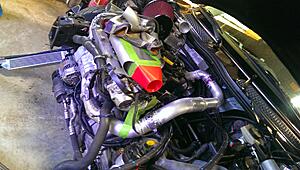
for now, just a few more pictures.
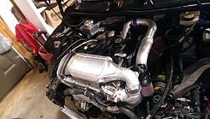
welded up compressor housing
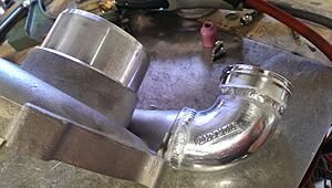
and a general plumbing shot.
hopefully the transitions in and out of the intercooler will be done today so I can pick them up and finish of the main part of the intake plumbing this evening
hmm. oh well!
little welding update!
still have a few things to work out, and some bits from McMasterCarr are coming in on monday. (first round of parts I ordered for my turbo vs SC boost controller setup were a little undersized for my liking)
changed out the spring in the piston and now it works flawlessly.
Now i just need to mount it and finish up the intake plumbing.
for now, just a few more pictures.
welded up compressor housing

and a general plumbing shot.

hopefully the transitions in and out of the intercooler will be done today so I can pick them up and finish of the main part of the intake plumbing this evening
Thread Starter
|
5th Gear
Joined: Aug 2008
Posts: 1,100
Likes: 13
From: Inman, SC
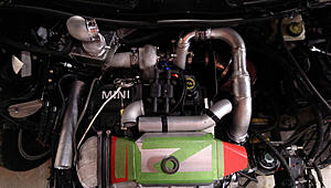
this intercooler is a bell core. haha!
The laminova one worked fantastic, but it had a small leak, so it is now a rather intricate "conversation starter" / art piece in my place of residence. haha!
(bell core is a standard core. this one is designed for water to air, but everything gets welded, so no leaks.. ever... )
The laminova one worked fantastic, but it had a small leak, so it is now a rather intricate "conversation starter" / art piece in my place of residence. haha!
(bell core is a standard core. this one is designed for water to air, but everything gets welded, so no leaks.. ever... )
Thread Starter
|
5th Gear
Joined: Aug 2008
Posts: 1,100
Likes: 13
From: Inman, SC
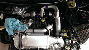
stiffer spring, assembled, and mounted!

this should be mostly a giveaway as to what this is for now.
haha!
another shot

will probably make the nose mount out of metal here shortly.
Was just easier to get the angle and length down right with plastic first.
and the last bit of hinting as to what this is all for
this should be mostly a giveaway as to what this is for now.
haha!
another shot

will probably make the nose mount out of metal here shortly.
Was just easier to get the angle and length down right with plastic first.
and the last bit of hinting as to what this is all for
3rd Gear
Joined: Dec 2013
Posts: 253
Likes: 0
Lathe
I'm using a Harbor Freight Mini Lathe in my 1 car garage for making small parts. I also have a Micro Mill by the same outfit. They each cost under $500...I have made a couple of solid billet 6061 aluminum GPS mounts. One for myself and one this week for Aloha Dee of AlphaMinis in So Cal.
You guys know that I have been searching the net for small machine lathes now, don't you? Why is it that everything I do costs money? I just have to learn to do even just a tiny bit of this.
My last project was silver soldering a bicycle frame that I built in the late 70s. That bike is still hanging in my garage (the bike is fine, but its motor needs new gaskets or something).
My last project was silver soldering a bicycle frame that I built in the late 70s. That bike is still hanging in my garage (the bike is fine, but its motor needs new gaskets or something).
Thread Starter
|
5th Gear
Joined: Aug 2008
Posts: 1,100
Likes: 13
From: Inman, SC
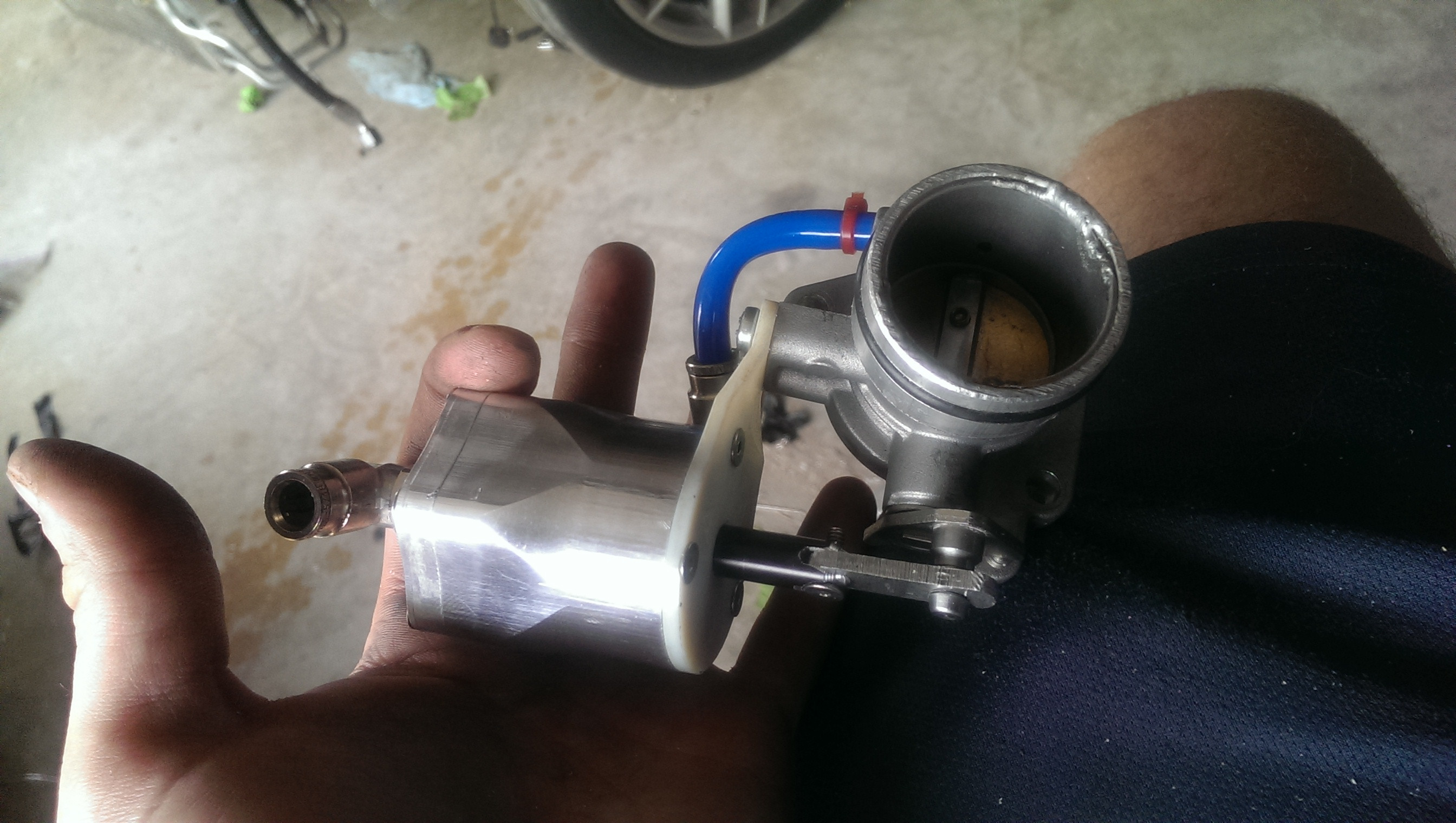
many different things in progress.
Too tired to write descriptions, but at least I can get you some images and captions for your friday morning.
started work on re-locating resevoir and pump to trunk for a2w system.
sheet metal bits came in.
Ended up having to send these back several times over the past two weeks. Long story. Ended up having to cut and re-weld a good bit on the SC horn exit one to make it work.

another

on the car with the DV welded on
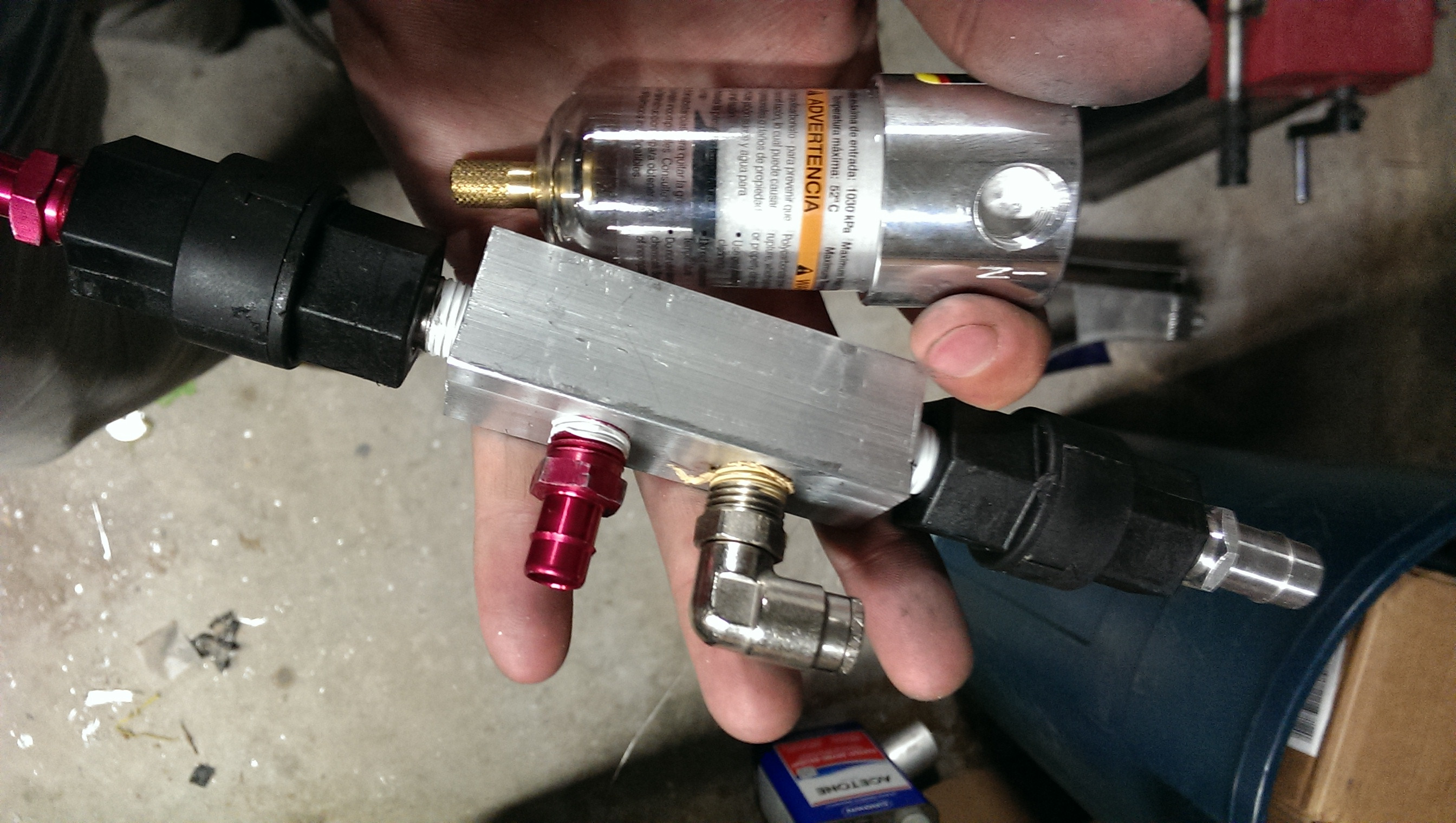
and a vacuum generation block.
(2 check valves that allow it to pull vacuum from the intake manifold or the turbo inlet venturi I made) distributes to crank case and brake booster.

Too tired to write descriptions, but at least I can get you some images and captions for your friday morning.
started work on re-locating resevoir and pump to trunk for a2w system.

sheet metal bits came in.
Ended up having to send these back several times over the past two weeks. Long story. Ended up having to cut and re-weld a good bit on the SC horn exit one to make it work.

another

on the car with the DV welded on

and a vacuum generation block.
(2 check valves that allow it to pull vacuum from the intake manifold or the turbo inlet venturi I made) distributes to crank case and brake booster.
5th Gear
Joined: Nov 2009
Posts: 771
Likes: 1
From: Port Orange, Florida
When this is all done, I want you to take this car into some random Mini Dealer in Kansas or Alabama, or someplace like that, and tell them that its making a funny noise. I just want to see their reaction.

2nd Gear
Joined: Sep 2012
Posts: 78
Likes: 0
 hidden camera please!
Thread Starter
|
5th Gear
Joined: Aug 2008
Posts: 1,100
Likes: 13
From: Inman, SC
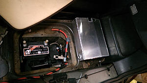
end tanks and fittings welded on, new intercooler resevoir in progress. (now just have to re-make a new trunk floor)
Brailie battery in position for mock up with pump sitting down in the hole as well.
lots of little stuff left too.
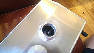
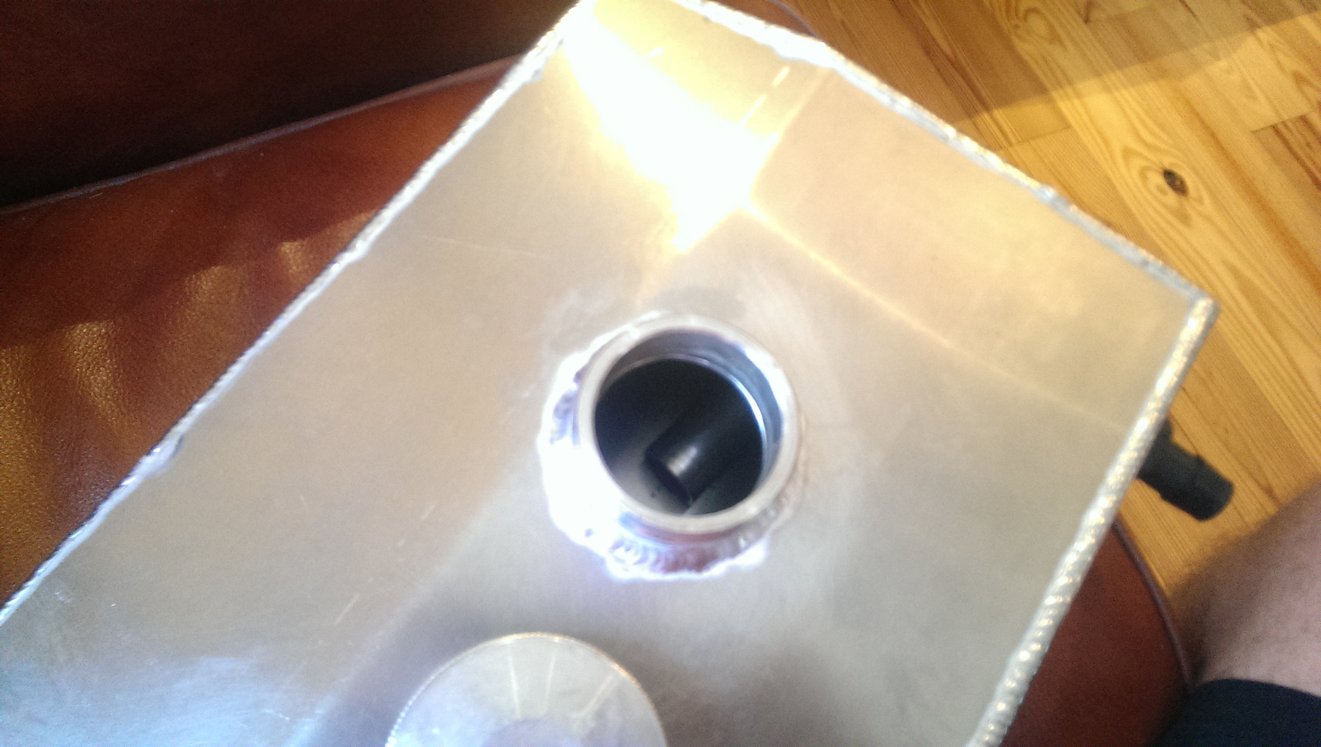
new tank

with a center pickup (pipe connects to lower corner fitting, should help to keep pump from starving in any directional acceleration it experiences. )
Brailie battery in position for mock up with pump sitting down in the hole as well.
lots of little stuff left too.

new tank

with a center pickup (pipe connects to lower corner fitting, should help to keep pump from starving in any directional acceleration it experiences. )
3rd Gear
Joined: Dec 2013
Posts: 253
Likes: 0
end tanks and fittings welded on, new intercooler resevoir in progress. (now just have to re-make a new trunk floor)
Brailie battery in position for mock up with pump sitting down in the hole as well.
lots of little stuff left too.
new tank
with a center pickup (pipe connects to lower corner fitting, should help to keep pump from starving in any directional acceleration it experiences. )
Brailie battery in position for mock up with pump sitting down in the hole as well.
lots of little stuff left too.
new tank
with a center pickup (pipe connects to lower corner fitting, should help to keep pump from starving in any directional acceleration it experiences. )