
Drivetrain My build. Teaser photos and updates


6th Gear

Joined: Jan 2013
Posts: 2,257
Likes: 15
From: Dover, NH
is it the newer mid engine? I dunno when they swapped from rear to mid for the cayman. its otherwise a solid choice, I have always preferred the cayman myself.


Thread Starter
|
5th Gear
Joined: Aug 2008
Posts: 1,100
Likes: 13
From: Inman, SC
Cayman has always (since it's induction in 2006) been a mid engine platform 
One of the reasons it doesnt have any more power than it does as it is better balanced than the 911
Can't have the little brother outrunning the flagship now can we porsche?
One of the reasons it doesnt have any more power than it does as it is better balanced than the 911
Can't have the little brother outrunning the flagship now can we porsche?
6th Gear
Joined: Jan 2013
Posts: 2,257
Likes: 15
From: Dover, NH
well hopefully that are finnally admitting that with the GT4
Thread Starter
|
5th Gear
Joined: Aug 2008
Posts: 1,100
Likes: 13
From: Inman, SC
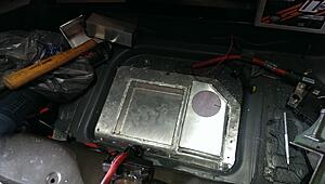
I made a hole!!!

And I promise I cursed less than 100 times while doing it.
The box that came out is not so pretty let's just say..
That underbody coating is some resilient *****.
As is the body seam filler
And the damn spot welds seem to always hold an edge somehow...
(let's just say the floor was not flat at first. took some light massaging with a backer block and a hammer.
Then a wire wheel to remove all the paint and coatings down to bare metal.
Then I had some metallic silver por15 rust prevention paint on hand (the stuff is the bees-knees. if you are ever doing rust repair work I highly suggest their product line)
So the floor section got re-painted that..
finally think I know what I am going to do back there. Not sure why id didnt come to me sooner. eh. oh well.
Also been out of the country for a few weeks. and put 2.5k miles on the new cayman in the two weeks I have been home XD
Thread Starter
|
5th Gear
Joined: Aug 2008
Posts: 1,100
Likes: 13
From: Inman, SC
not dead. just slow going. Too many other projects.
anywho, finally finished the new water tank +battery box design
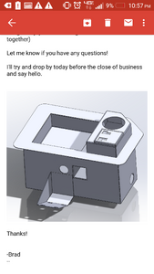
Then had it waterjet cut, and after I got those bits back I spent some time folding them on a brake
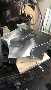
even doing some baffling

And to show (roughly) what it will look like from the top, tahda!
Still a lot of holes to drill, a lot more welding to do, a few more fittings to turn out and a lot of warping to be had and then straightened (the bane of sheet metal working)
In other news, I have been playing a lot on a lathe and picking up new skills.
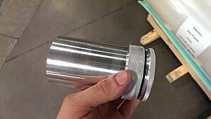
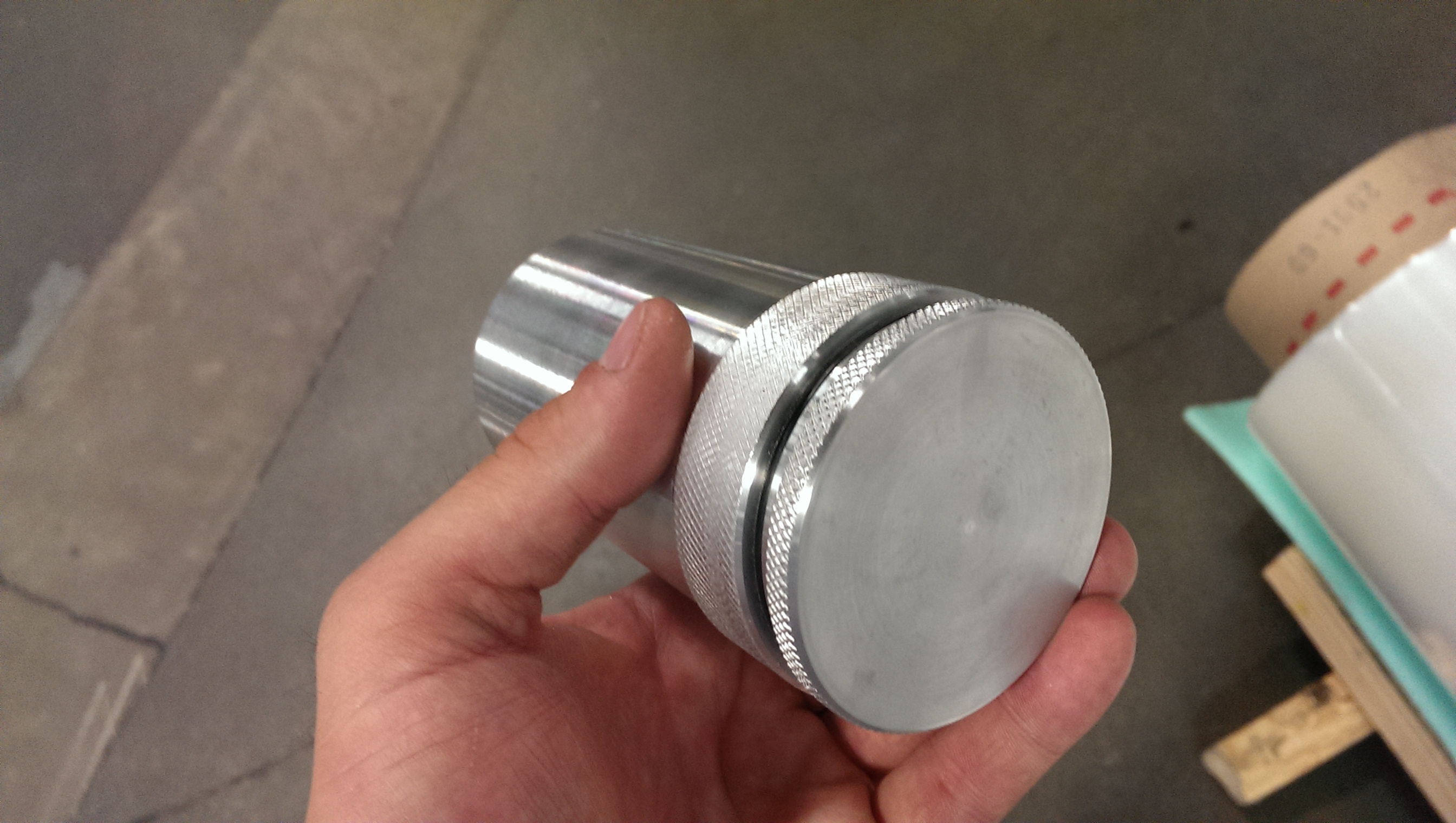
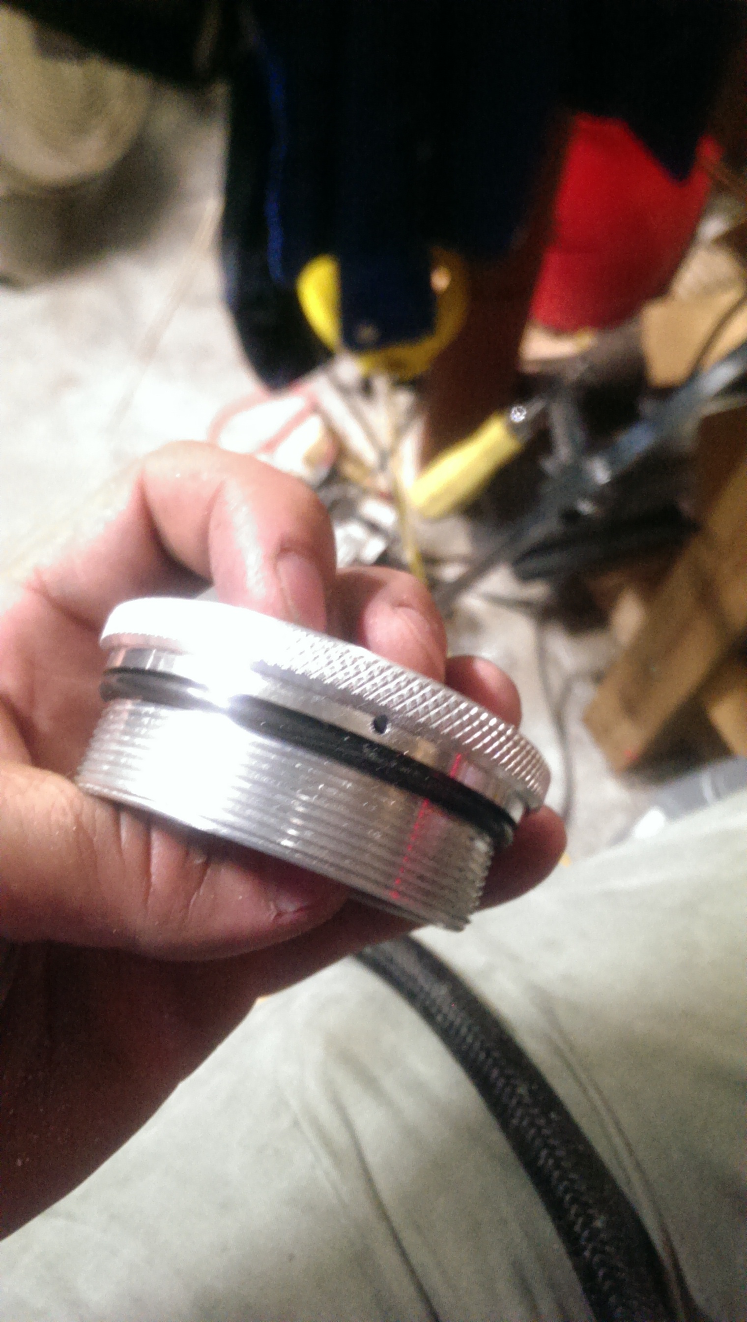
Needed a different power steering resevoir, so.. I decided to make one out of a billet...
It will actually have a weld on it as the main body was made from 2.5" sch80 6061 pipe turned down to size (instead of hogging out a billet) but essentially this is the pre on the right and the post on the left (of what I have so far)

Still teaching myself how to do threads manually on a lathe, but this was my second successful set.


anywho, finally finished the new water tank +battery box design

Then had it waterjet cut, and after I got those bits back I spent some time folding them on a brake

even doing some baffling

And to show (roughly) what it will look like from the top, tahda!
Still a lot of holes to drill, a lot more welding to do, a few more fittings to turn out and a lot of warping to be had and then straightened (the bane of sheet metal working)
In other news, I have been playing a lot on a lathe and picking up new skills.
Needed a different power steering resevoir, so.. I decided to make one out of a billet...
It will actually have a weld on it as the main body was made from 2.5" sch80 6061 pipe turned down to size (instead of hogging out a billet) but essentially this is the pre on the right and the post on the left (of what I have so far)

Still teaching myself how to do threads manually on a lathe, but this was my second successful set.


Thread Starter
|
5th Gear
Joined: Aug 2008
Posts: 1,100
Likes: 13
From: Inman, SC
so much welding, prep etc has been going on.
you may want to grab a rather large bowl of popcorn...
Trying to get this thing done so I can have a base map on it and blast it down a airport runway in 2 months. O.O
So much to do.
Anywho,
Welded up the tank
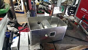
I have a new distaste for welding in the middle of sheet metal that I cannot clamp down.
It got massaged often with a hammer.
dropped the top part in place and drilled all of the rivet holes from under the car (through the factory spot-weld locations)
Then I took the bottom part, flipped it upside down on a flat surface, scored a line all the way around, and trimmed the box down so the whole top was flush. (bending left some variation in the hight of the sides)
Then I clamped the two together, and made it one piece.
no images for that.. sorry..
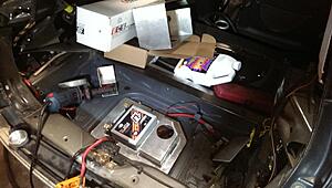
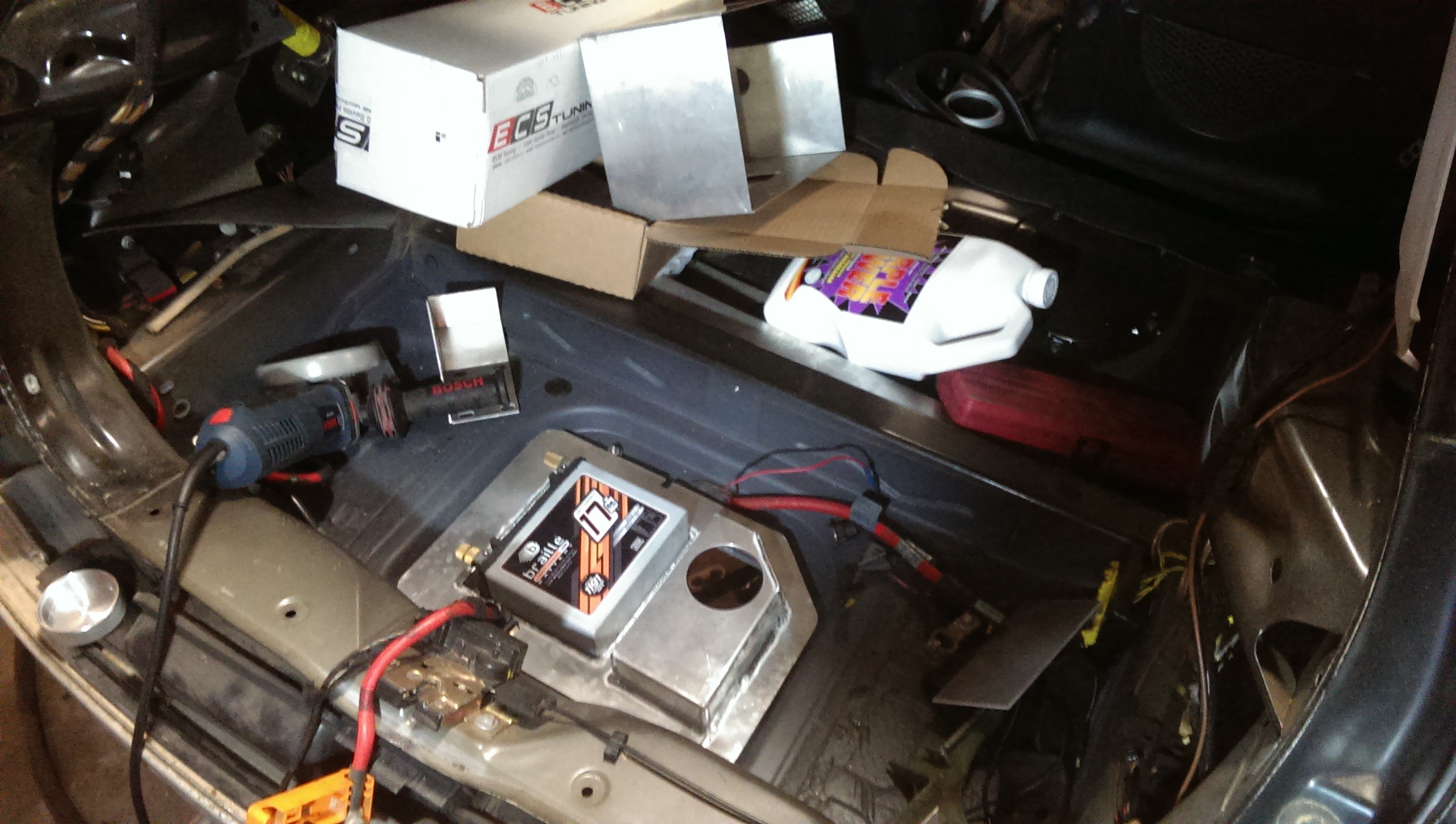
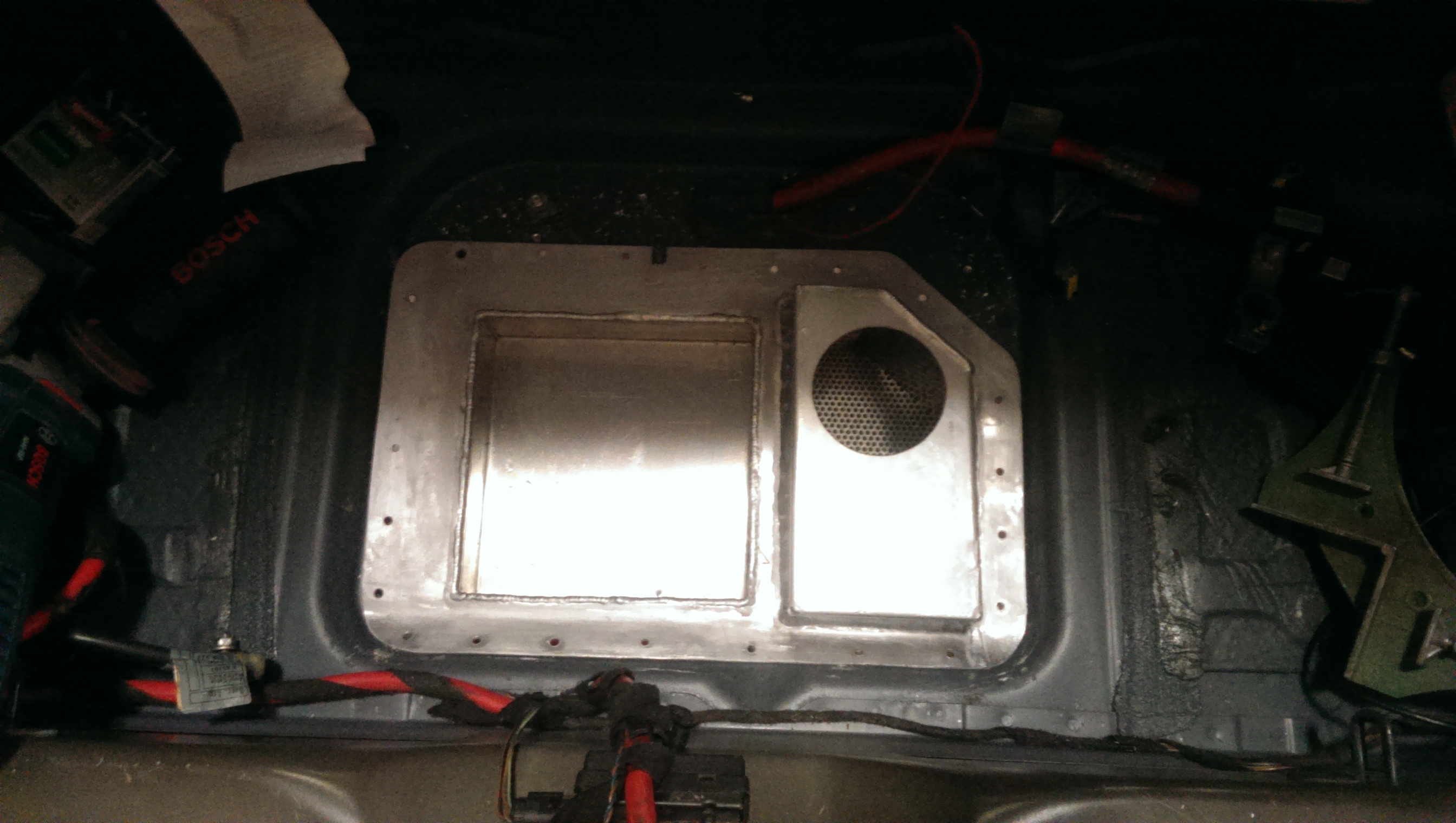
But here it is sitting back in place!
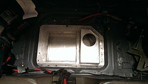
potato-photo

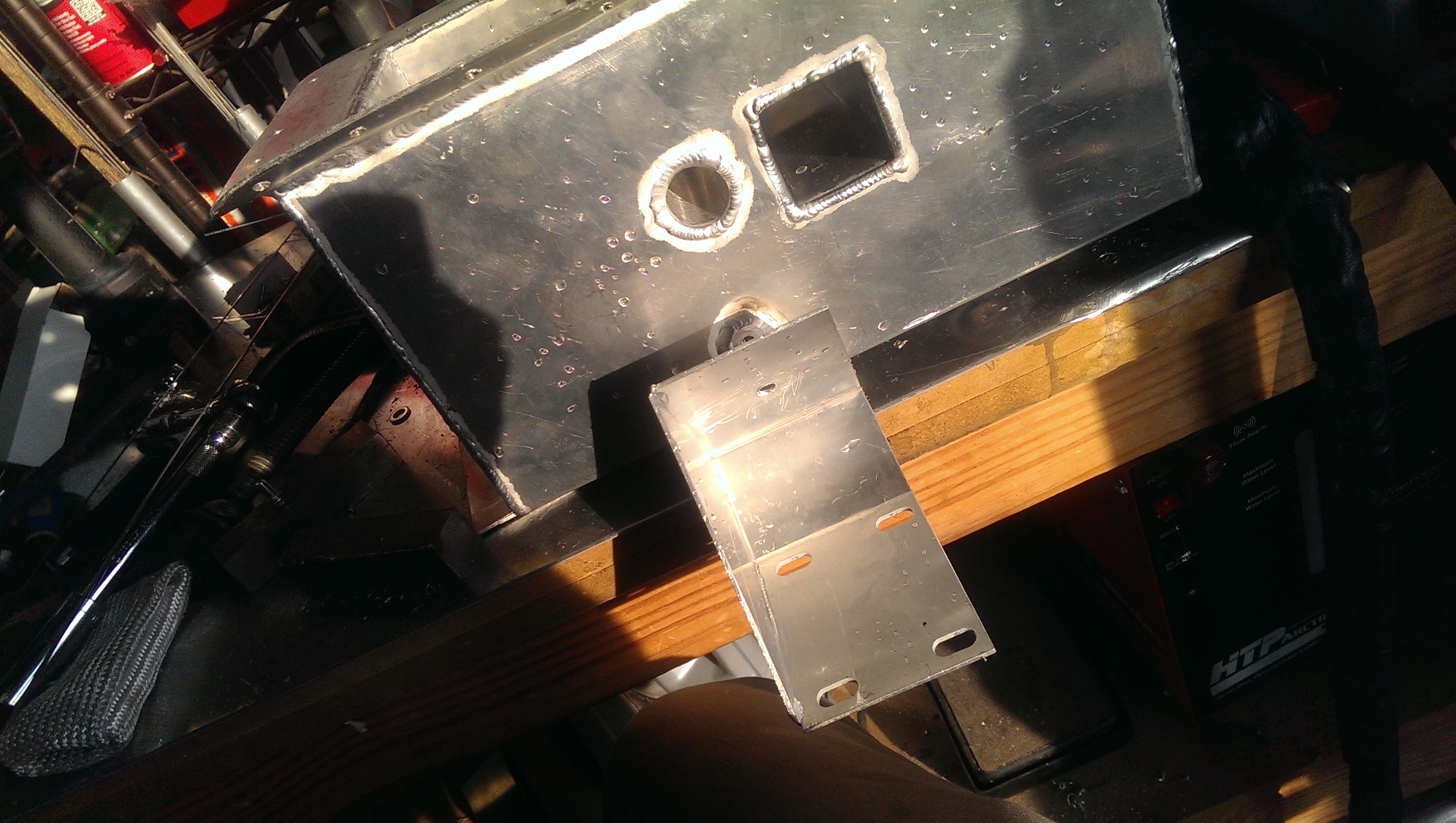
Now I needed to mount the pump bracket, and didnt want to turn out that many fittings (small fittings are boring and I wanted something different)
Could't weld it straight on as the tank won't fit through the hole in the trunk with the pump bracket on..
So I decided to attach it with a hinge so it can swing out of the way.
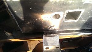
Had to turn out one fitting for the screw that will hold it up when it is in place.
Will probably need to add a second as the hinge has some play in it which lets the bracket move around the bolt as sort of a pivot (slightly) Second mount would be to stiffen it up and eliminate any vibration that may happen.

the square hole is the hose pass-through from the pump exit.
The round hole is where the level sensor for the tank goes. (if the water level ever drops below that hole it will engage the circuit and set off a light or buzzer or whatever I want it to do..)
Test mount
in place

Going to have to move the exhaust over. Probably means a new muffler.. ugh.. (center outlet instead of offset outlet)
best case - I cut both of the tubes leaving the muffler off and flip it around.
with the radiator

The pump bracket makes it so I am going to have to re-make the fan shroud. no biggie... will do that at some point soon.
pump hooked to tank supply.

And on to the power steering!! woohoo!!
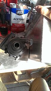
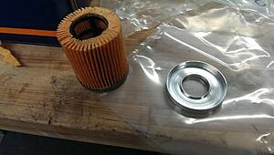
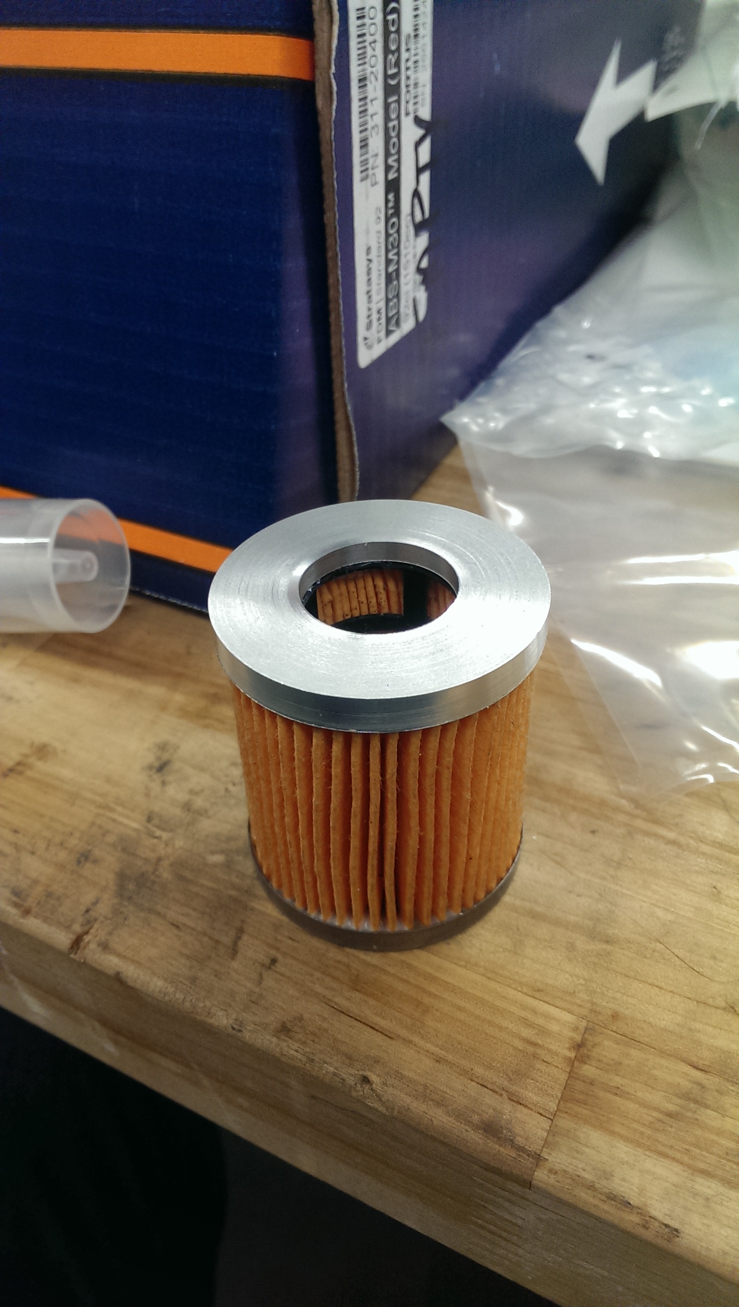
Needs a filter, so I went to advance, got the most narrow oil filter I could find. Ended up being a cartridge for a V6 camaro.
It was skinny, but long, so I trimmed it down on a bandsaw and turned out a new end cap.
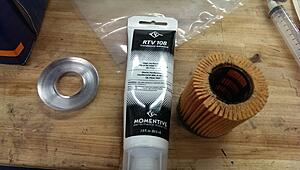
Then glued the new end-cap on with some RTV


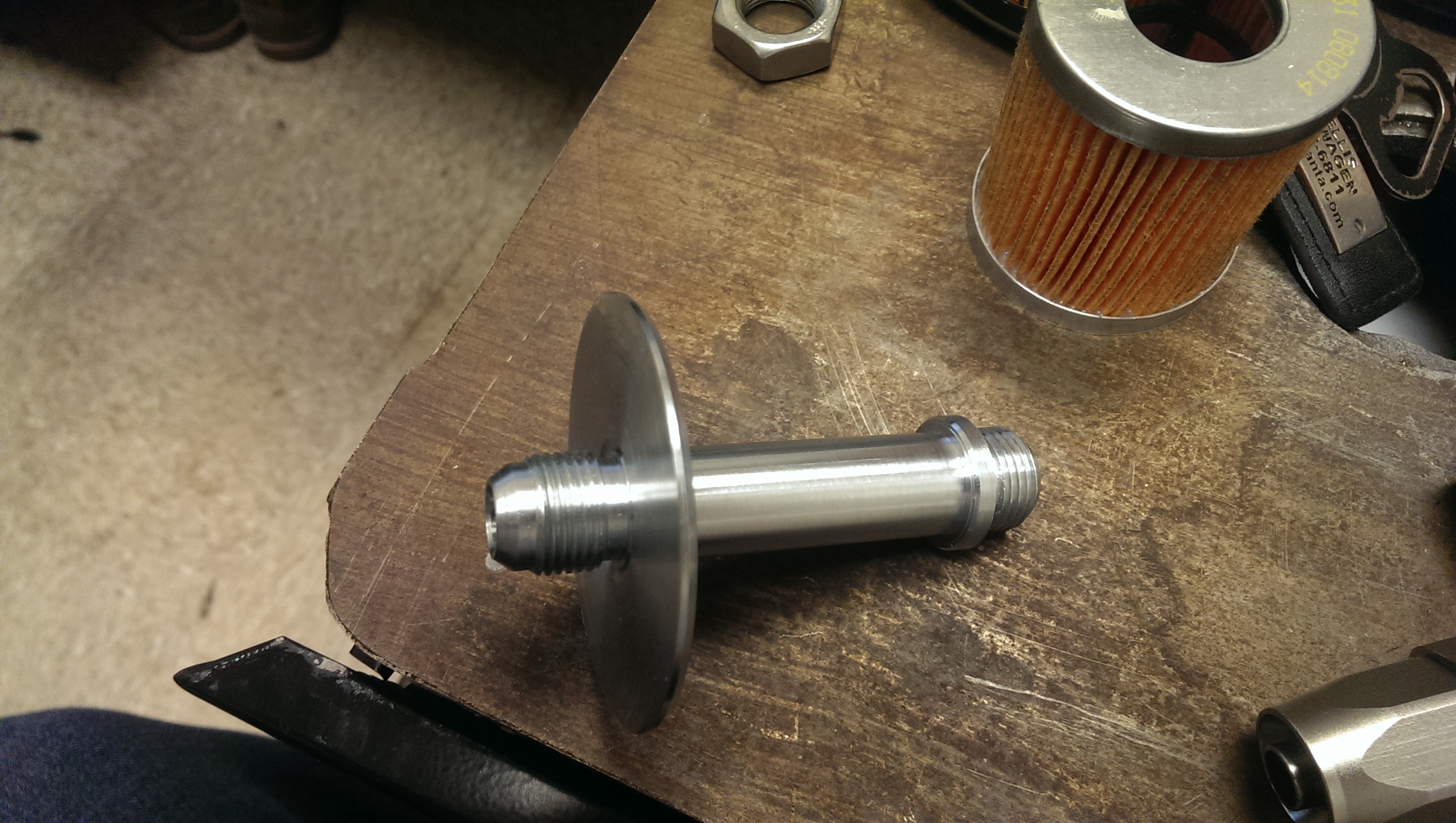
Then I turned out a stem for inside of the resevoir to
A. hold the filter on and in place.
B. have an AN-8 fitting on the bottom (3/4-16 thread with a 37� mating pitch and a 3/8" bore)
C. allow for a dip-stick to go into the top (1/2" bore. Will turn stem out later with o-ring to force fluid through the filter and not let it come through the top)- as well as modify the cap to the reservoir to allow for fluid-level checking)
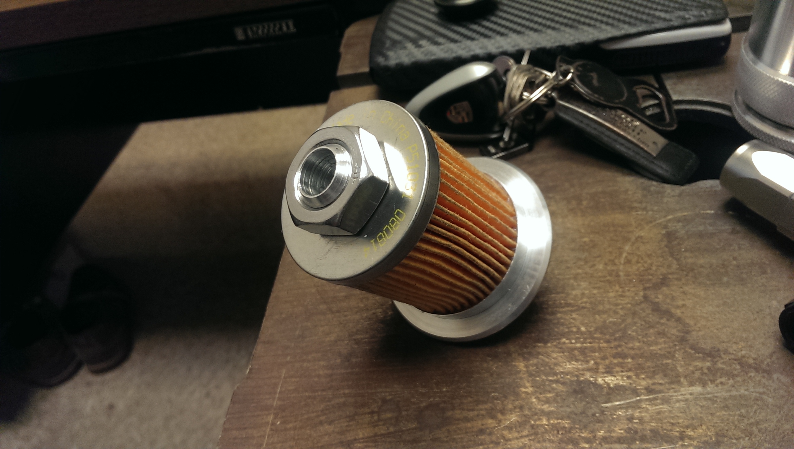
*the nut is temporary until I turn out a new fitting to do it's job.
*the tube inside the filter still needs to be slotted, but the bridgeport had another job on it that was set up for precision work and can't come off just yet.
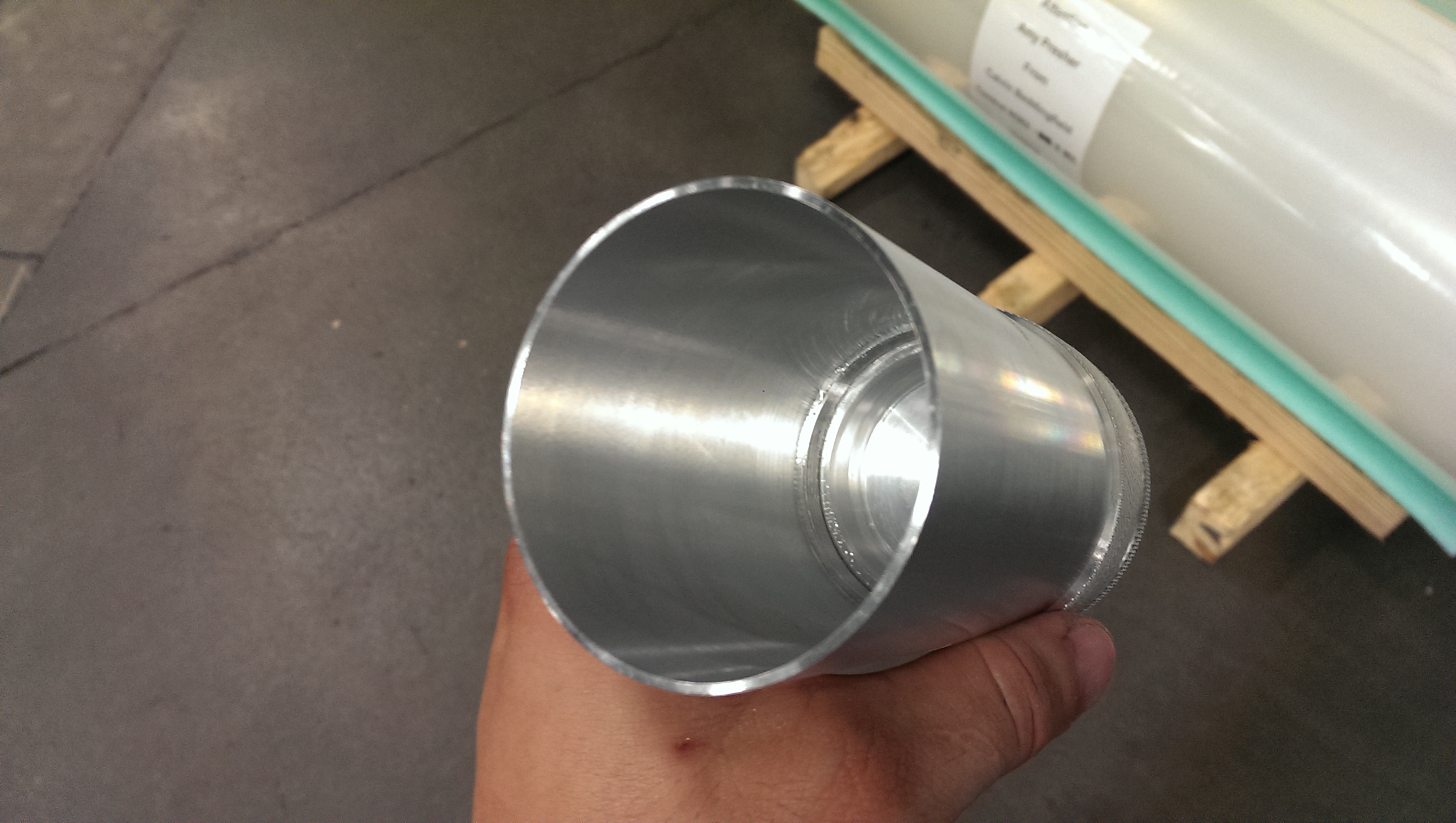
started out as a 5" long 3" round hunk of aluminum...

Slide the filter on

test clamp with nut

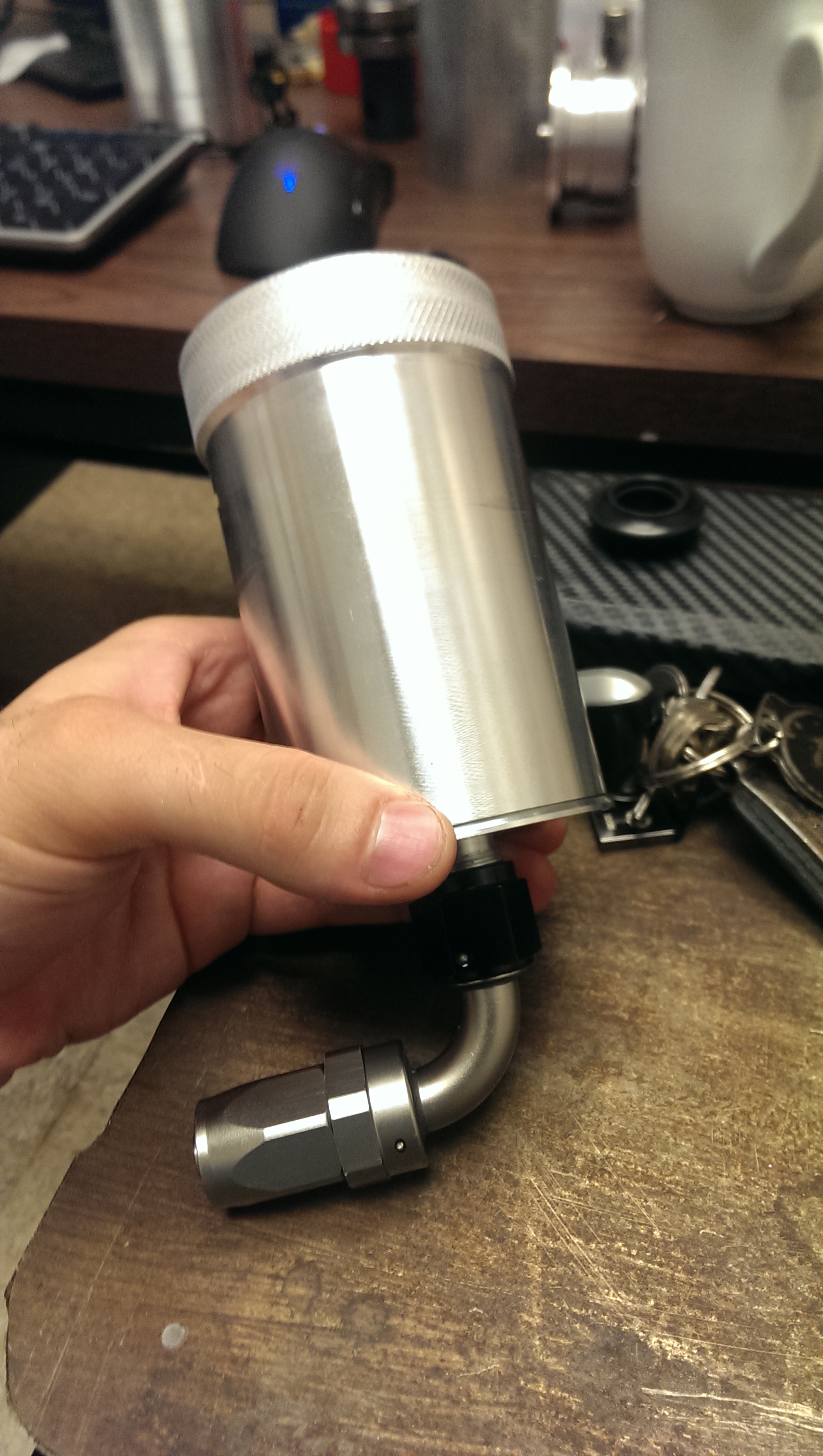
test AN fitting. It threads beautifully and seals perfectly!

joint to be welded.

A look from the top.

Thanks for following!
you may want to grab a rather large bowl of popcorn...
Trying to get this thing done so I can have a base map on it and blast it down a airport runway in 2 months. O.O
So much to do.
Anywho,
Welded up the tank

I have a new distaste for welding in the middle of sheet metal that I cannot clamp down.
It got massaged often with a hammer.
dropped the top part in place and drilled all of the rivet holes from under the car (through the factory spot-weld locations)

Then I took the bottom part, flipped it upside down on a flat surface, scored a line all the way around, and trimmed the box down so the whole top was flush. (bending left some variation in the hight of the sides)
Then I clamped the two together, and made it one piece.
no images for that.. sorry..
But here it is sitting back in place!
potato-photo

Now I needed to mount the pump bracket, and didnt want to turn out that many fittings (small fittings are boring and I wanted something different)
Could't weld it straight on as the tank won't fit through the hole in the trunk with the pump bracket on..
So I decided to attach it with a hinge so it can swing out of the way.

Had to turn out one fitting for the screw that will hold it up when it is in place.
Will probably need to add a second as the hinge has some play in it which lets the bracket move around the bolt as sort of a pivot (slightly) Second mount would be to stiffen it up and eliminate any vibration that may happen.
the square hole is the hose pass-through from the pump exit.
The round hole is where the level sensor for the tank goes. (if the water level ever drops below that hole it will engage the circuit and set off a light or buzzer or whatever I want it to do..)
Test mount

in place

Going to have to move the exhaust over. Probably means a new muffler.. ugh.. (center outlet instead of offset outlet)
best case - I cut both of the tubes leaving the muffler off and flip it around.
with the radiator

The pump bracket makes it so I am going to have to re-make the fan shroud. no biggie... will do that at some point soon.
pump hooked to tank supply.

And on to the power steering!! woohoo!!
Needs a filter, so I went to advance, got the most narrow oil filter I could find. Ended up being a cartridge for a V6 camaro.
It was skinny, but long, so I trimmed it down on a bandsaw and turned out a new end cap.

Then glued the new end-cap on with some RTV


Then I turned out a stem for inside of the resevoir to
A. hold the filter on and in place.
B. have an AN-8 fitting on the bottom (3/4-16 thread with a 37� mating pitch and a 3/8" bore)
C. allow for a dip-stick to go into the top (1/2" bore. Will turn stem out later with o-ring to force fluid through the filter and not let it come through the top)- as well as modify the cap to the reservoir to allow for fluid-level checking)
*the nut is temporary until I turn out a new fitting to do it's job.
*the tube inside the filter still needs to be slotted, but the bridgeport had another job on it that was set up for precision work and can't come off just yet.
started out as a 5" long 3" round hunk of aluminum...
Slide the filter on

test clamp with nut
test AN fitting. It threads beautifully and seals perfectly!

joint to be welded.
A look from the top.

Thanks for following!


3rd Gear
Joined: Jul 2014
Posts: 215
Likes: 2
The **** you do makes me just want to crawl into your ear hole sometimes I'm just poke that Brain, that ability idiot you have to visualize the system as a gift please make sure you do use something to change the world with it. You have any experience with cad design and C&C in small precision parts? my design expertise is scribbling on paper, and I'm determined to make a proper turbine supercharger at some point in my life. I've scene two companies attempted but they just didn't make any damn sense and just consisted of a tube of rotating turbines all the same size which they hope to produce boost.bto properly work you need stationary vanes in between your rotating vanes as well as a variable guide vane to begin spinning the turbine compression sections by utilizing a vairiable pitch to ramp speed. The compressor section needs to gradually decrease in size and then fed into a similar 2nd compressor section except a much tighter and higher in compression. The second high compression section should have an open passage surrounding it to allow bypass while low compressor spools up. The whole assembly will be driven by a concentric shaft connected to the forward variable guide vane runs through the whole turbine section and attached to a belt driven pulley that sits aft of the out take. In between the pulley and hi compressor section output should be a large turbine that is allowed to free span until brought up to speed in which it will also drive to the front stater vane and in turn began to illuminate parasitic lost from the motor at the high-end of the power band. The front stater vanes what extend past the low compressor section housing into a Nother surrounding passage that acts as a idle bypass, all the bypass sections operate purely by the laws of fluid dynamics kind of like a turbo fan engine,. The set up wood in my opinion be the perfect charging system because by design it ramps power and eventually eliminates parasitic loss purely by The natural laws of pressure. I've drawn it up and I think with a high precision CNC equipment wouldn't be terribly impossible to make, after roll jet engines for RC aircraft are becoming pretty common now so I know the equipment to do it should be available readily. I however grow up in a household where my dad thought computers were never going to catch on so I am severely crippled when it comes to making a digital concept. You seem like one of the only people I would be confident coulddesign it. You seem quite avid in solid works, i'm still trying to get the program to install
3rd Gear
Joined: Dec 2013
Posts: 253
Likes: 0
The **** you do makes me just want to crawl into your ear hole sometimes I'm just poke that Brain, that ability idiot you have to visualize the system as a gift please make sure you do use something to change the world with it. You have any experience with cad design and C&C in small precision parts? my design expertise is scribbling on paper, and I'm determined to make a proper turbine supercharger at some point in my life. I've scene two companies attempted but they just didn't make any damn sense and just consisted of a tube of rotating turbines all the same size which they hope to produce boost.bto properly work you need stationary vanes in between your rotating vanes as well as a variable guide vane to begin spinning the turbine compression sections by utilizing a vairiable pitch to ramp speed. The compressor section needs to gradually decrease in size and then fed into a similar 2nd compressor section except a much tighter and higher in compression. The second high compression section should have an open passage surrounding it to allow bypass while low compressor spools up. The whole assembly will be driven by a concentric shaft connected to the forward variable guide vane runs through the whole turbine section and attached to a belt driven pulley that sits aft of the out take. In between the pulley and hi compressor section output should be a large turbine that is allowed to free span until brought up to speed in which it will also drive to the front stater vane and in turn began to illuminate parasitic lost from the motor at the high-end of the power band. The front stater vanes what extend past the low compressor section housing into a Nother surrounding passage that acts as a idle bypass, all the bypass sections operate purely by the laws of fluid dynamics kind of like a turbo fan engine,. The set up wood in my opinion be the perfect charging system because by design it ramps power and eventually eliminates parasitic loss purely by The natural laws of pressure. I've drawn it up and I think with a high precision CNC equipment wouldn't be terribly impossible to make, after roll jet engines for RC aircraft are becoming pretty common now so I know the equipment to do it should be available readily. I however grow up in a household where my dad thought computers were never going to catch on so I am severely crippled when it comes to making a digital concept. You seem like one of the only people I would be confident coulddesign it. You seem quite avid in solid works, i'm still trying to get the program to install
3rd Gear
Joined: Jul 2014
Posts: 215
Likes: 2
Well it's no secret that my designs based off a jet engine, after all my background was as a turbo shaft jet mechanic. While there are very similar principles, my design is intended just for suck blow, not suck bang blow, as a combustion section probably wouldn't be the greatest thing for IAT. I may not be as obviously gifted as you, but I do know a thing or two, and am especially familiar with turbines. I spent several years tearing down and rebuilding them as well as being an inflight fcf engineer tuning them. I've always been very adept to visualizing how things work, and putting them together. Unfortunately, I never learned to fabricate, or had the chance to go to an engineering program to really know the math. I'm just a guy who finally reached an age where I've realized life is short, and instead of thinking what could've been, Ive embarked on a personal Renaissance to try to learn everything I wish I had. I already have three degrees and am disenchanted by the college lie, and it's ROI, and am embarking on a DIY university approach. I've been reading a lot lately and am attempting to teach myself the math behind engineering, but I also know that nothing beats reaching out to others you admire for their craft and trying to soak up all they have to teach. There isn't a more efficient fuel to power output engine than a jet, so I can only assumate that a air compressor based on the same principles would follow suit. My guesstimation to why a successful turbine SC hasn't come into fruition is because jet mechs and internal combustion mechs as well as their engineers remain pretty seperate from eachother. I've sketched a few designs, and if you wouldn't mind looking at them and letting me know your thoughts it'd be appreciated, I'm sure you'll giggle but it's understandable, I'm currently an audio engineer professionally and am often barraged by bedroom producers recordings who want feedback, and yes it's hard not to wAnna bury your face in Your palm, but we all start somewhere, and I too used to be the hobbyist bugging the pros, just as I am now. Since everyone stole the music, our careers are drying up, forcing me to make most my money mixing concerts, and that just isn't my passion. So I'm ready for another change, and mechanical design has always been somthing I wanted to do. So I'm gonna keep latching to the pros until I reach my goal, this would be my fourth career change, so I'm getting the motions to a science. Also, I'm working on another project that I'll keep under wraps until it starts to materialize, but I really need a larger throttle body, and boring ours isn't the route I wanna go, but I do know a vipec guy who's swapped in a bmw 535 TB, I however am starting basic on tuning fundamentals and am using the bytetronik. Is a true standalone the only way to do a model swap, or is there a way for me to do it? I haven't fount a lot of info on how the ECU and TB communicate, but all the VDO TBs look pretty identical in the electronic side. Any insight on the principles involved and a possible work around would be stellar. Thanks dude.
3rd Gear
Joined: Jul 2014
Posts: 215
Likes: 2
Btw, my comment was intended for soccer, but any constructive comments are appreciated. No ones an expert at everthing, so ridicule only stifles progress, and makes the perp look like a ****. However gearhead I too am a antagonist and contriving in my humor and always playful about it. However in the advent of text based communication, the context is lost, I myself am often taken as rude in comments, when I'm just being coy. So I'll assume it was in good nature. Any advice you may have is also appreciated.
3rd Gear
Joined: Jul 2014
Posts: 215
Likes: 2
All joking aside, you did make me think of somthing with your size reference. RC jet engines have become pretty readable, and might be a good start, just gotta remove the combustion section, and modify the compressor turbine to a pulley. Well not "just", the actual housing fabrication and modifications would still be an undertaking, but having the compressor sections already built would eliminate 90 percent of the work. You just made this actually seem feasible and financially plausible. That was the best sarcastic remark I've ever received, thanks
3rd Gear
Joined: Jul 2014
Posts: 215
Likes: 2
You sorta agitated me at first, but now I'm realizing you just type the same way I kid, so now they're becoming quite humorous. We'd make good drinking buddies, that is unless your actually being malicious, in which case you'd just be a ****. I that is the case we'd still make good drinking buddies.
Thread Starter
|
5th Gear
Joined: Aug 2008
Posts: 1,100
Likes: 13
From: Inman, SC
lol you two.
eMINI,
The problem is a centrifugal compressor is just the better option for this scenario.
When your packaging is in a line and you are using a central shaft and producing thrust along it's axis, then that style of compressor is advantageous and it uses the walls of the housing to translate the centripetal movement of the fan blades, accelerating the air down the length of the blade and off the tip into a focused axial thrust into the combustion section.
To take this and then make the exit go somewhere other than down the axis, the air needs to make a turn to leave.
If you have to make a turn, why would you have a dead space at the end of the compressor zone to allow for the air to make the turn? It's not an efficient use of space.
So in order to allow the air to turn, and to aid in preventing back-flow, make the compressor housing expand and have blades in that section that follow the expansion contour and have a slightly decreasing pitch angle and a narrow opening.
This will allow for higher pressure ratios and allow the air to make an exit from the compressor. Keeping the exit from the compressor fairly narrow also helps to keep these aspects.
Now, unfortunately if you take the design I just layed out, and instead of making it multiple fan blades, you compact it down into one complex blade.. you get a turbocharger compressor housing.
in terms of bang/$ it is the KISS method for making a good, reliable, efficient, compact compressor.
Not saying there are not improvements to be made, but at this stage they are more difficult... all the easy stuff has already been sorted
3rd Gear
Joined: Jul 2014
Posts: 215
Likes: 2
I think we're actually pretty close to the same page, however trying to explain a complex unit as such in words is just an exercise in futility. I'll send you some sketches of three different designs I've come up with. And lemme know what you think.
One more thing, why has no one built a parallel charged system, or compounded roots system in a staged configuration like old air craft. Again. I'll send you some designs so you can poke holes in them. The technical critiquing of my conceptual pipe dreams is really how I learn best. To learn what won't work is as valuable as learning what does.
One more thing, why has no one built a parallel charged system, or compounded roots system in a staged configuration like old air craft. Again. I'll send you some designs so you can poke holes in them. The technical critiquing of my conceptual pipe dreams is really how I learn best. To learn what won't work is as valuable as learning what does.
Thread Starter
|
5th Gear
Joined: Aug 2008
Posts: 1,100
Likes: 13
From: Inman, SC
I did not see the throttle body question. The VDO throttles with the same connector are plug and play. But! You are using a larger valve (or smaller) without any compensation to the factory throttle PID control for idle, which can cause that control loop to become unstable when it experiences a large upset (blipping the throttle and it just surges like crazy until it finally settles down or the engine dies. ) not sure if FA53 has unlocked the PID tables for everyone yet... I had a special version that let me do that ish before I went standalone. Normally changing those tables in FA53 would cause your car to go into limp mode though...
3rd Gear
Joined: Dec 2013
Posts: 253
Likes: 0
My build. Teaser photos and updates
eMINI, I really wasn't trying to be rude, just thought that we would need more room under the hood (bonnet)for straight line air flow to make it work on our small scale cars. I too love new ideas and would really like to see your idea come to fruition.
Thread Starter
|
5th Gear
Joined: Aug 2008
Posts: 1,100
Likes: 13
From: Inman, SC
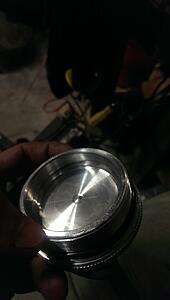
okay. so another (small) update)
free-hand drilled a small vent-hole into the cap.

meets up with the small hole in the middle of the cap here
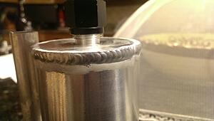
welded on the return tube and the main bottom piece. AN-8 supply, AN-10 return
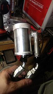
weld was.. meh. not bad.. but not fantastic.
then I took some .080 aluminum sheet, used a 2.5" hole saw at the edge of the sheet to get the rough shape, marked where I needed the mount hole, drilled that out.
Then I spent ~15 minutes with a rotary burr making the 2.5" diameter half-circle into a 2.6" half circle so it fit the resevoir.
I then cut out the rough shape I wanted (tapering 'traingle' ), clamped the piece in the vice and used a soft block (annealed aluminum chunk I had laying around) and a hammer to beat the sides over slowly to make the folded sides.
Then I welded it up!
(sorry, no pictures of the process, just the end result)
One of the better looking items I have made with basic-ish tools in the home garage without using shop tools.

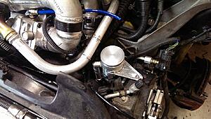
That is all for now!
New radiator fan is inbound.. turns out while the OEM fan shroud cleared the new intake with the OEM fan and shroud.. same cannot be said for the mishimoto radiator setup. it is slightly thicker and pushed the shroud back just enough so that the front radiator support will not go all the way on easily and the motor contacts the plumbing.
Whoopsie.
free-hand drilled a small vent-hole into the cap.
meets up with the small hole in the middle of the cap here

welded on the return tube and the main bottom piece. AN-8 supply, AN-10 return

weld was.. meh. not bad.. but not fantastic.

then I took some .080 aluminum sheet, used a 2.5" hole saw at the edge of the sheet to get the rough shape, marked where I needed the mount hole, drilled that out.
Then I spent ~15 minutes with a rotary burr making the 2.5" diameter half-circle into a 2.6" half circle so it fit the resevoir.
I then cut out the rough shape I wanted (tapering 'traingle' ), clamped the piece in the vice and used a soft block (annealed aluminum chunk I had laying around) and a hammer to beat the sides over slowly to make the folded sides.
Then I welded it up!
(sorry, no pictures of the process, just the end result)
One of the better looking items I have made with basic-ish tools in the home garage without using shop tools.


That is all for now!
New radiator fan is inbound.. turns out while the OEM fan shroud cleared the new intake with the OEM fan and shroud.. same cannot be said for the mishimoto radiator setup. it is slightly thicker and pushed the shroud back just enough so that the front radiator support will not go all the way on easily and the motor contacts the plumbing.
Whoopsie.


This thread is epic and gets better and better. Well done. 
__________________

MINI Guru/ MINI Owner Since 2004 | NEW Lifetime Part Replacement | Local Pickup
Milltek | Genuine MINI | Forge Motorsport | NM Engineering | ECS Performance | M7 Speed
Customer Service Hours: 8am-8pm EST|Sales Team Hours: 8am-11pm | SAT 10am-7pm 800.924.5172
MINI Guru/ MINI Owner Since 2004 | NEW Lifetime Part Replacement | Local Pickup
Milltek | Genuine MINI | Forge Motorsport | NM Engineering | ECS Performance | M7 Speed
Customer Service Hours: 8am-8pm EST|Sales Team Hours: 8am-11pm | SAT 10am-7pm 800.924.5172
3rd Gear
Joined: Jul 2014
Posts: 215
Likes: 2
Can I just pay you to weld together a trellis subframe with mounts for a k20 conversion? Lol, whatever you'd charge would only be a fraction to what mini parts cost. I'm tired of seeing honda parts at a quarter of the price. Im ready to jump ship and make a bastard mini. Japanese and german love child. Along with my ducati my garage would be a mechanized axis powers. Great work though. You're inspiring to pull my welder out and get to practicing.