Drivetrain My build. Teaser photos and updates


Thread Starter
|
5th Gear
Joined: Aug 2008
Posts: 1,100
Likes: 13
From: Inman, SC
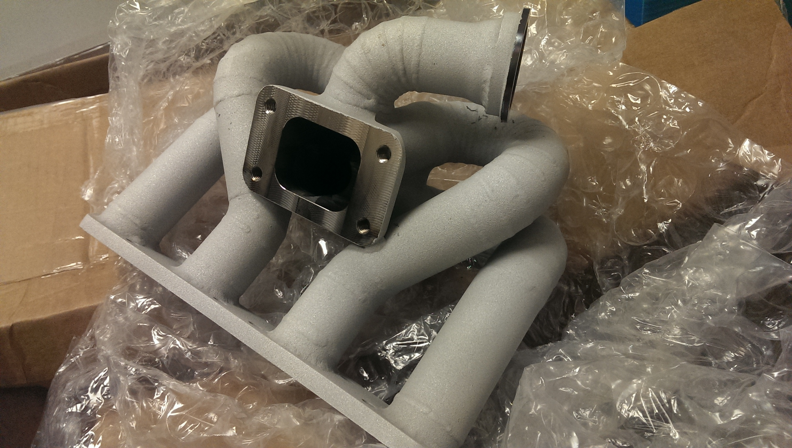
Turbo exhaust parts! (made by me) back from coating at swaintech!
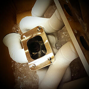

Turbine housing and first bit of down pipe

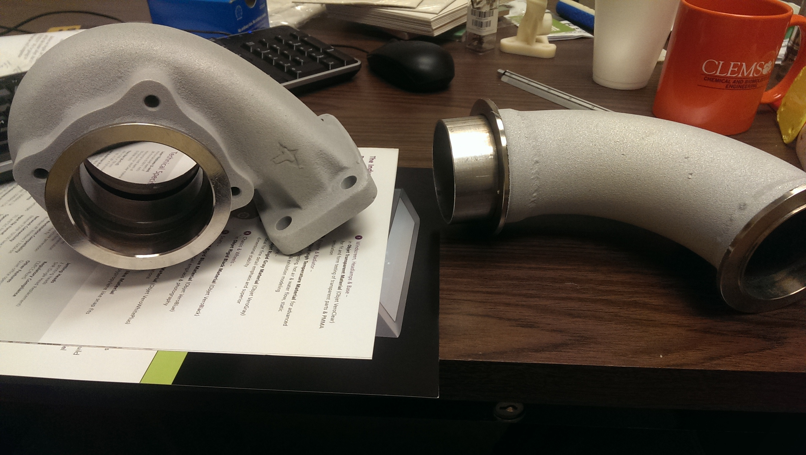
and the rest of the down pipe, waste gate tube, and cat!
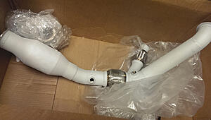

Hope you guys enjoy custom work!
More coming in the next few days


Turbine housing and first bit of down pipe
and the rest of the down pipe, waste gate tube, and cat!

Hope you guys enjoy custom work!
More coming in the next few days

Thread Starter
|
5th Gear
Joined: Aug 2008
Posts: 1,100
Likes: 13
From: Inman, SC
It is a thermal barrier ceramic coating from Swaintech out of upstate NY.
its ~.025" thick, so much thicker than your exhaust or grill paints, and actually holds up over time and insulates the exhaust parts (where as other ceramic coatings do not). Not the cheapest thing, but better than the titanium wrap in terms of performance, looks cleaner, and no annoying titanium splinters in my fingers
its ~.025" thick, so much thicker than your exhaust or grill paints, and actually holds up over time and insulates the exhaust parts (where as other ceramic coatings do not). Not the cheapest thing, but better than the titanium wrap in terms of performance, looks cleaner, and no annoying titanium splinters in my fingers
Thread Starter
|
5th Gear
Joined: Aug 2008
Posts: 1,100
Likes: 13
From: Inman, SC
yes. It is a thermal barrier coating.
Surface is slightly rough.
Ceramic coatings come in many flavors, so it is impossible to say it "feels like a ceramic" other than the fact that it is rock hard.
surface texture is close to 220 grit sand paper though, maybe a little more coarse.
Surface is slightly rough.
Ceramic coatings come in many flavors, so it is impossible to say it "feels like a ceramic" other than the fact that it is rock hard.
surface texture is close to 220 grit sand paper though, maybe a little more coarse.


Thread Starter
|
5th Gear
Joined: Aug 2008
Posts: 1,100
Likes: 13
From: Inman, SC
still a street car! and they really dont rob much power, so for the sake of not having to cut into a ceramic coated part later in life if I move I went ahead and put in one.
It is a high flow ceramic core, and is a pretty open structure, so yes. I put one in.
Plus if I ever do move out of state and have to pass a tailpipe sniff and visual check, I should not have any issues.
It is a high flow ceramic core, and is a pretty open structure, so yes. I put one in.
Plus if I ever do move out of state and have to pass a tailpipe sniff and visual check, I should not have any issues.

5th Gear
Joined: Nov 2009
Posts: 771
Likes: 1
From: Port Orange, Florida
Will you have to add additional heat barriers to the floor along the exhaust route or does that thermal barrier just move more BTUs out the back without radiating it away along the length?
Thread Starter
|
5th Gear
Joined: Aug 2008
Posts: 1,100
Likes: 13
From: Inman, SC
well it moves more of the heat into the main section of exhaust. So now that the exhaust gasses are hotter, it will move more out the back, but then again the deltaT (differential temperature) between the inside and outside of the exhaust along the entire length is now greater, and will increase heat transfer rate through the metal and to its surroundings.
Now, it is not a huge concern as the turbine housing actually will soak up A LOT of this heat and convert it into energy. This is, essentially, how a turbine works after all! converts hot high pressure gas into colder, lower pressure gas, extracting the thermal energy out and turning it into mechanical energy!
So, in a way, it will be conveying the heat from the engine bay out into the main section of exhaust, but it will already contain less heat than it did with the supercharged setup, so YAY!
Also, one thing people dont really think about / know is that stainless steel is actually significantly worse at thermal conduction than plain steel ( a good thing here) Which means it naturally insulates more, and helps scavenging than a mild steel pipe would.
Thermal conductivity on stainless is in the neighborhood of
19 W/(m*�K) @250�C [watts/[meter metal thickness*absolute temperature in kelvin differential]
while plain steel is 47 W/(m*�K) @250�C !
quite a difference!


I'm an ex-MCS owner who just spent an irresponsible amount of time at work reading this entire thread. Awesome fab and design work! I'm an ME myself, so I love seeing this kind of stuff. You must work for an awesome company to allow you to use their resources so much. I have a full prototype center at my disposal (SLA, CNC, EDM, etc) but have never used it to the extent you have. You lucked out! Keep the progress coming!

1st Gear
Joined: Jul 2007
Posts: 26
Likes: 0
Thread Starter
|
5th Gear
Joined: Aug 2008
Posts: 1,100
Likes: 13
From: Inman, SC
I only get to use it on the weekends and after hours really.
A lot of the work was actually done when they were "training" me on the machine. I quickly discovered new ways to use the machine, or jurry-rig things so that we could cut them, and they let me cut whatever I want when I am doing exploratory work.
I buy the bits, on my own time, and pay for all materials.
In return, we have learned a lot in terms of the capabilities of the machine, and now cut aluminum (this is a router CNC) 50X faster than the machine would out of the box without going over 40% spindle load.
(proper bits for materials, travel speed adjustmends, cut depth adjustments, other stuff)
This is why the intercooler plates are being cut elsewhere though. Not exploratory work :/
But at least I found a local guy who does things at-cost for home and hobbiest jobs. They just take forever to get finished! haha. (understandable though, low priority, but the price is right)
Thread Starter
|
5th Gear
Joined: Aug 2008
Posts: 1,100
Likes: 13
From: Inman, SC
Unfortunately all the tech's at the local dealer that I used to know quite well have left. I used to just walk straight past the service guy and out into the shop to ask one of the guys a question.
Fellow by the name of Brent was always best, but he left due to that dealer being a suckfest (I really do hate them) and went to an independent local mini/bmw shop.
Anywho,
Thank you everyone for the kind words!
And now down to bid-ness
this evenings tasks: fix the exhaust.
So I made a booboo: when I was welding up the last part of the downpipe (connecting it to the main exhaust), apparently I forgot to hold it in place where it would clear the swaybar as it moves.
ruh roh!
but thankfully this was easily fixed without having to cut through any swaintech coating! phew!
Ended up just taking 1" out of the main run of pipe between the resonator and the front exhaust hangar.
inch removed and tac'd in place.

Test fit revealed that my measurements were accurate and everything lines up! (sorry, no pics. Hard to fit anything other than me and wrenches under the car)
Finish welded (i guess I forgot to take a pic) and she is now back in the car and everything is happy!
how this worked:
Doing this allowed the downpipe to swing upwards, pulling it away from the swaybar, and re-connect to the exhaust. (hooray for having 3 joints that can move! (v-bands) but in swinging "up" it moved the rear end of the down-pipe up and back. Now I did not have to rotate it far, only a few degrees. This moved it up about an inch, and back about an inch.
Good thing is my flex section was a bit back, so it only had to move by a few degrees as well to pull the end back down so that it could mate up with the exhaust.
Time will tell if this causes issues, but I am running with it for now
(something tells me it may.. I have issues with flex sections, although they are infinitely better than donuts imho.)
And onwards!!
so, I also need a coolant overflow tank... seeing as the stock one is
A: ugly, and
B: I have no where to put it.
So I am opting for a smaller one, in a not very logical location, but I will just heat shield the crap out of it.
Right over the downpipe!
Figured it cant be too bad when the OE one was over the header

Not finished yet, but that is all I had done for this evening. Had an after-hours meeting, then home, got a small snack, and the exhaust just took a while to take measurements, cut, tac, test fit, take it back off, clean, purge, weld, put it back on and bolt everything up to make sure nothing hits.
Anywho,
onward to this!
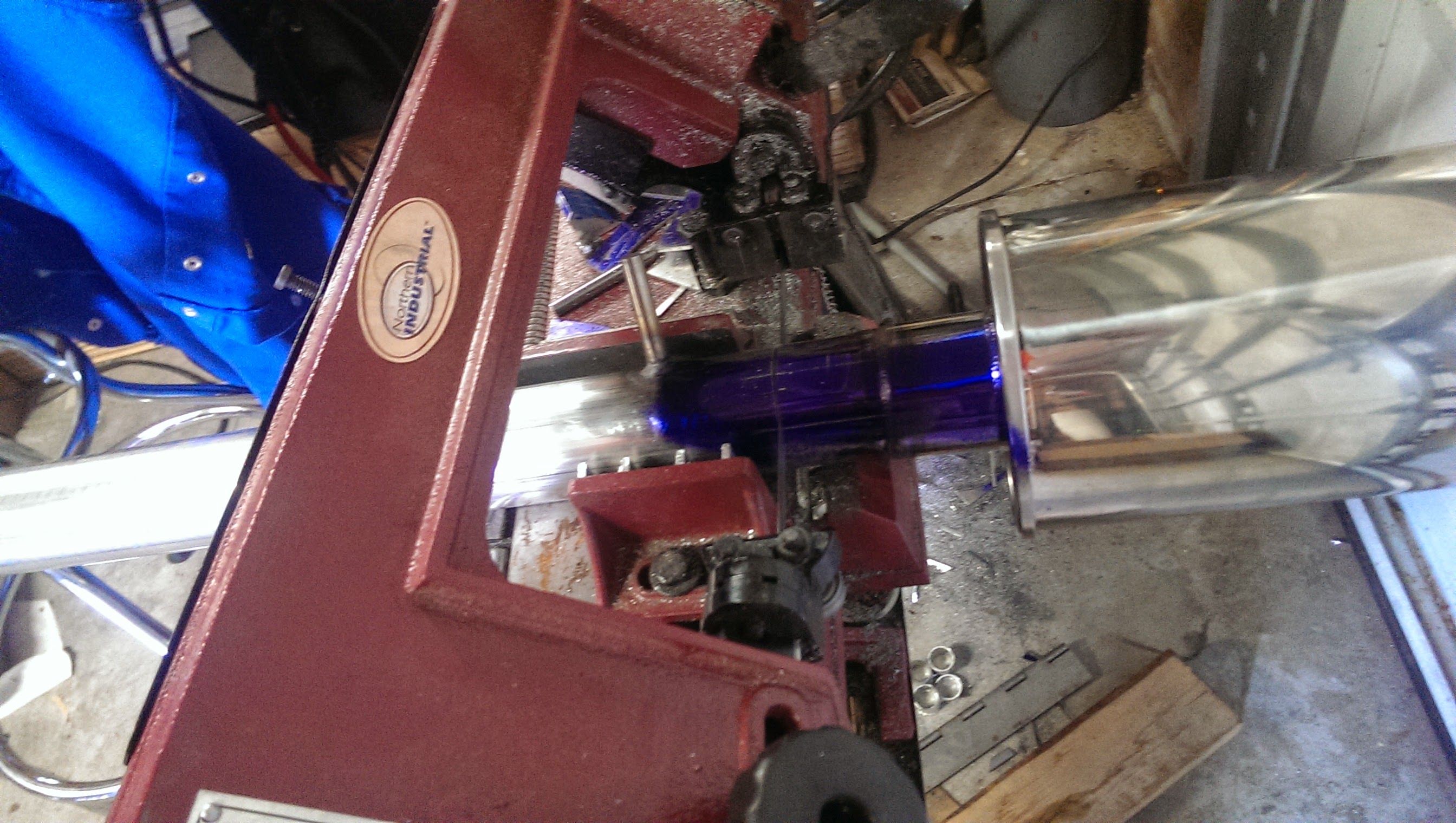
so I started with flat sheet as usual. Traced the pattern of the bend on the new rear heat shield / engine bay trim I made, and then cut out the plate. Measured the back side length, cut another piece and then clamped it in my vice and bent it by hand.
Welded the two together and this is how it started out today (did those things last evening)
(ignore the two pegs, those were not there when I started)
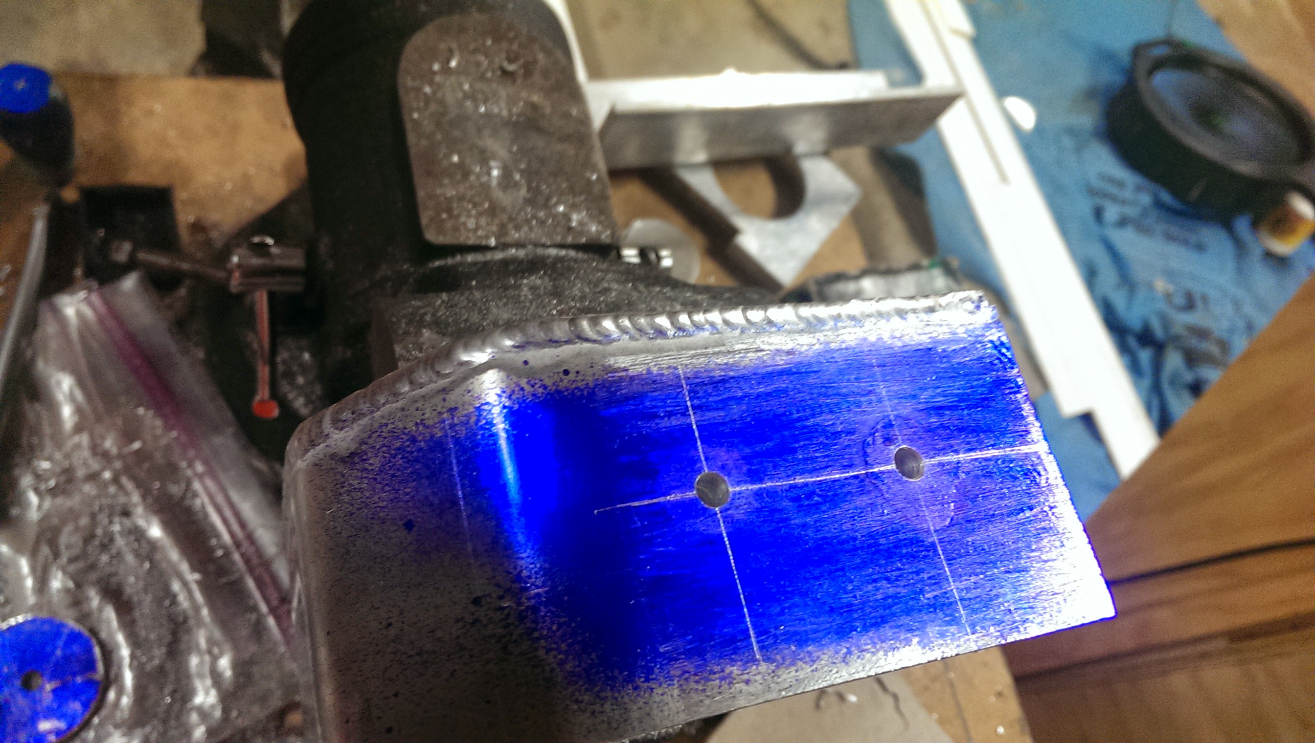
anywho, from there I used my calipers to measure out and scratch the aluminum for where I wanted the bolts to go to hold this thing on.
I marked the holes, used an automatic center punch to mark them, and then drilled small-ish pilot holes.
From here I took the piece, clamped it in the car where I wanted it, and then transfer punched the center of those holes I was drilling into the engine bay trim (so that the holes will be concentric and I don't have to have a lot of slop + washers)
I drilled out the punched spots in the engine trim to 6.5mm (for bolt clearance)
Then I used a step bit to drill out the pilot holes in the WIP resevoir to 0.5".
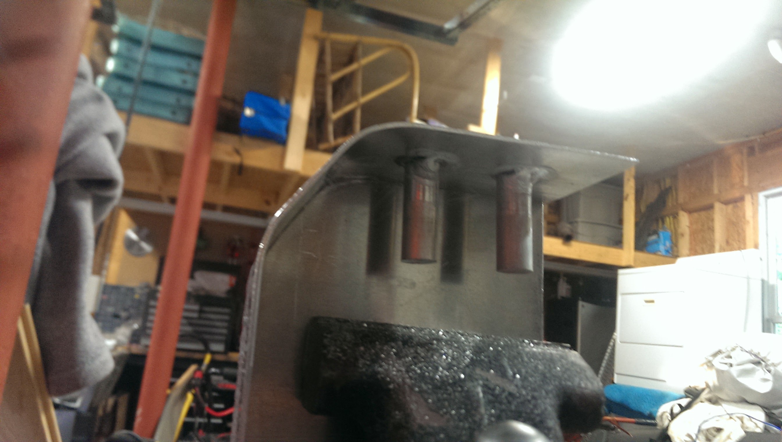
I cut two small lengths of 1/2" aluminum rod, lined them up over the holes, tac'd them from the back side (see image of piece in vice above) , and then I filled in the hole I drilled from the other side, welding the "pegs" to the sheet.
I welded over on purpose, and then filed the outside back flat.
Re-marked the centers of where the holes were (using the dimensions I used to mark them originally)
And drilled 5mm holes ~1" deep (I know, I like to switch units.
)
Then I removed the blue, filled the holes with aluminum cutting fluid and tapped the holes for M6-1.0

test fit 1:
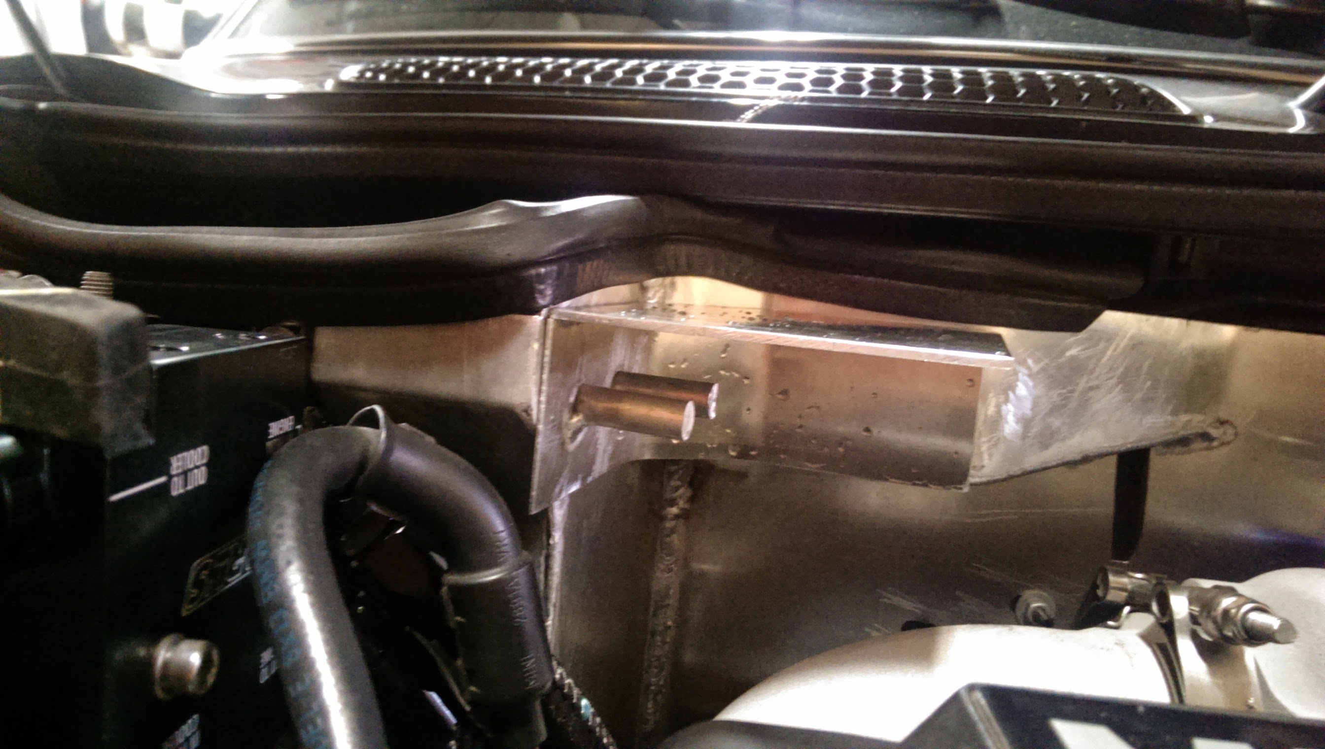
test fit 2:

Everything lined up nicely!
Rest of the evening was just cutting out the metal for the front two sides
and bending it in my vice

chamfering the front corner, and then welding it up
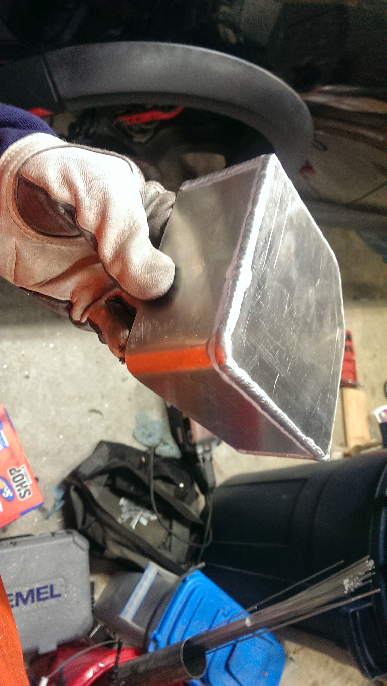
as she currently sits

it is about half the volume of the original unit unfortunately, but I am tinkering with the idea of extending the bottom down.. not sure yet, which is partly why i did not finish it this evening.
Need time to reflect and decide.
Hope you enjoyed!


Thread Starter
|
5th Gear
Joined: Aug 2008
Posts: 1,100
Likes: 13
From: Inman, SC
no walk through this evening, just some final shots.
Did a little bit of welding, but then my upper back muscles started cramping so I called it quits while I was ahead.
Anywho,
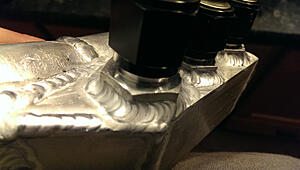
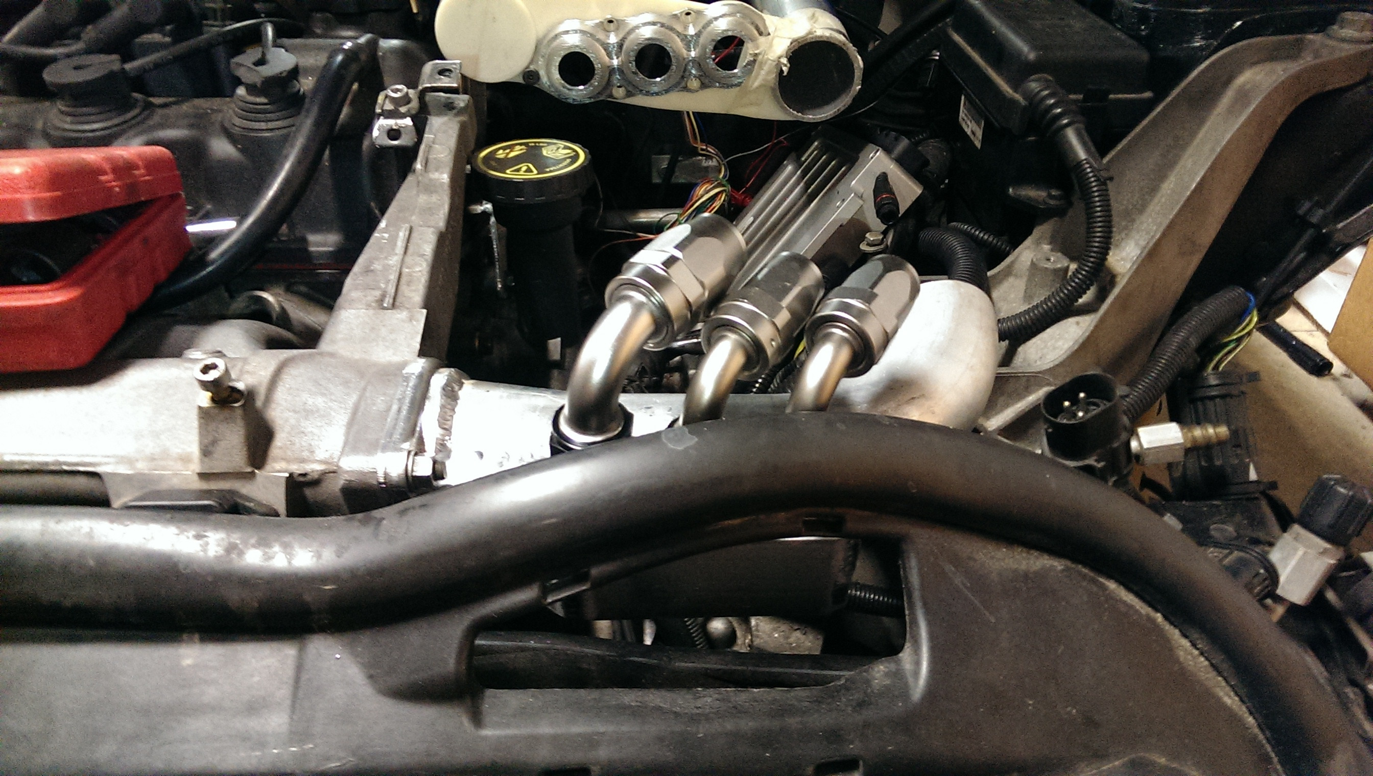
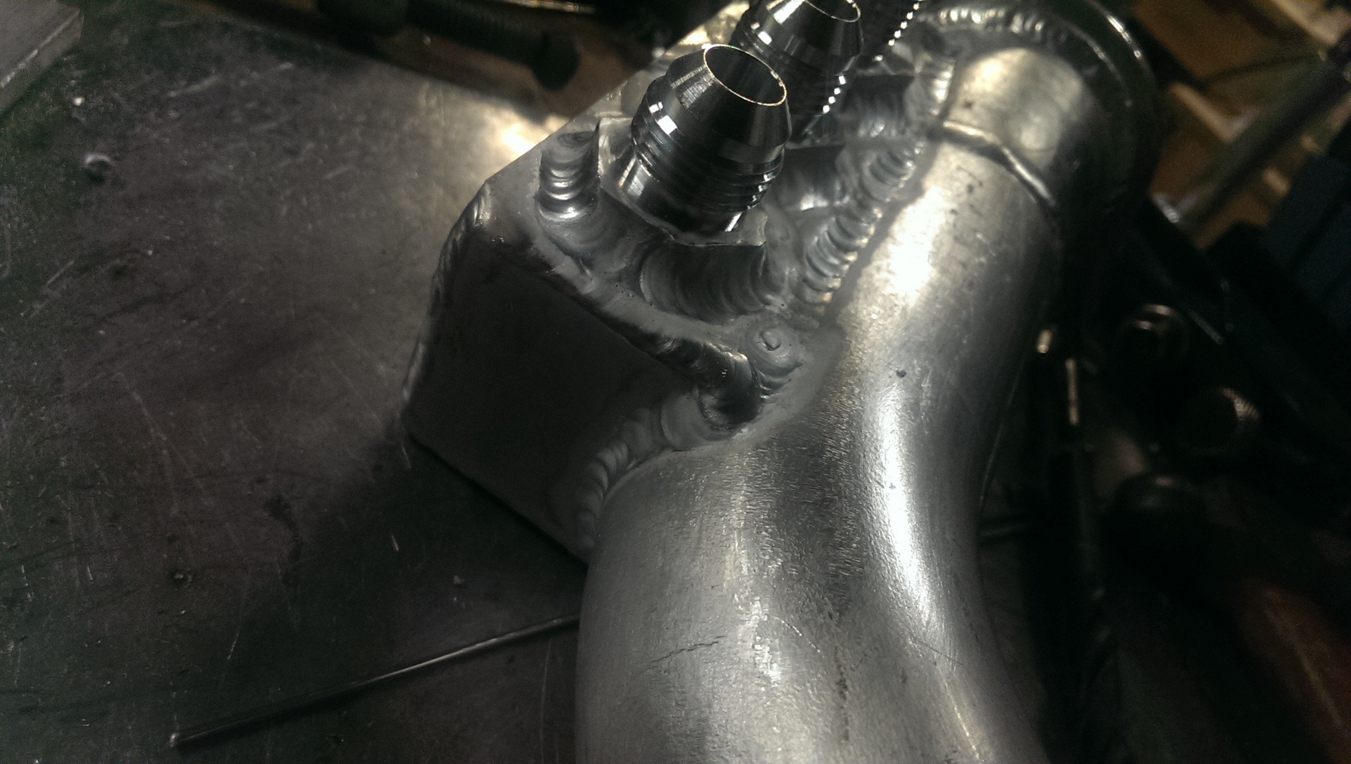
I needed a manifold for water distribution to the intercooler and turbo. Turbo has -10 AN lines (yes! -10! ) and the intercooler takes 2x-8 inlets, while the pump outlet is 3/4 barb. fun.
I have not put the barb on yet, need to go turn that, but, While looking for a place to mount this manifold, I had the great idea (in my mind at least) of just welding it straight to the inlet tube to the intake manifold! Should be cool water anywho, and it is post intercooler, so worst it could do is take a fraction of a degree off of my inlet temps (lol!)
And if I am honest, I got a bit lucky with the fitting clearance when it was all said and done. haha!
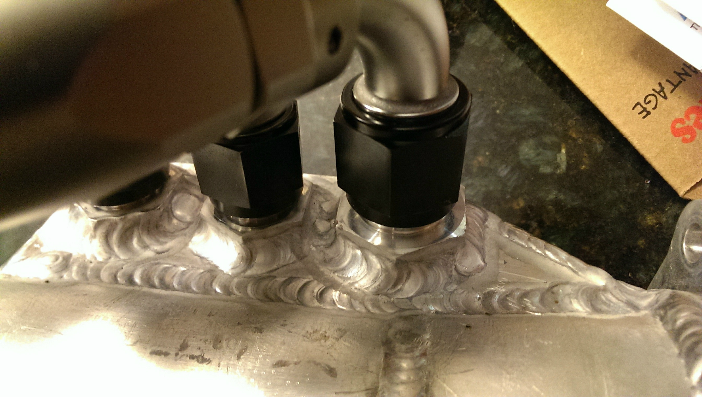
fyi: my aluminum welds look a lot better recently because I switched to a 2% lanth and started just putting a small flat on the tip instead of using pure tungsten and letting it ball.
cut it close:


welds and more welds


Did a little bit of welding, but then my upper back muscles started cramping so I called it quits while I was ahead.
Anywho,
I needed a manifold for water distribution to the intercooler and turbo. Turbo has -10 AN lines (yes! -10! ) and the intercooler takes 2x-8 inlets, while the pump outlet is 3/4 barb. fun.
I have not put the barb on yet, need to go turn that, but, While looking for a place to mount this manifold, I had the great idea (in my mind at least) of just welding it straight to the inlet tube to the intake manifold! Should be cool water anywho, and it is post intercooler, so worst it could do is take a fraction of a degree off of my inlet temps (lol!)
And if I am honest, I got a bit lucky with the fitting clearance when it was all said and done. haha!
fyi: my aluminum welds look a lot better recently because I switched to a 2% lanth and started just putting a small flat on the tip instead of using pure tungsten and letting it ball.
cut it close:


welds and more welds

Thread Starter
|
5th Gear
Joined: Aug 2008
Posts: 1,100
Likes: 13
From: Inman, SC
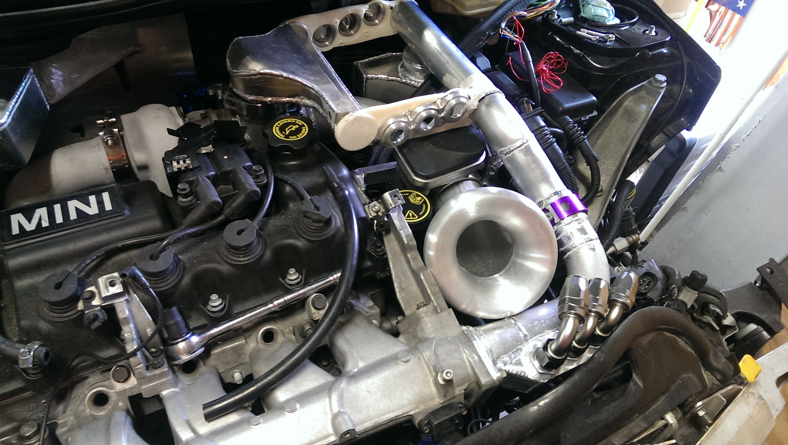
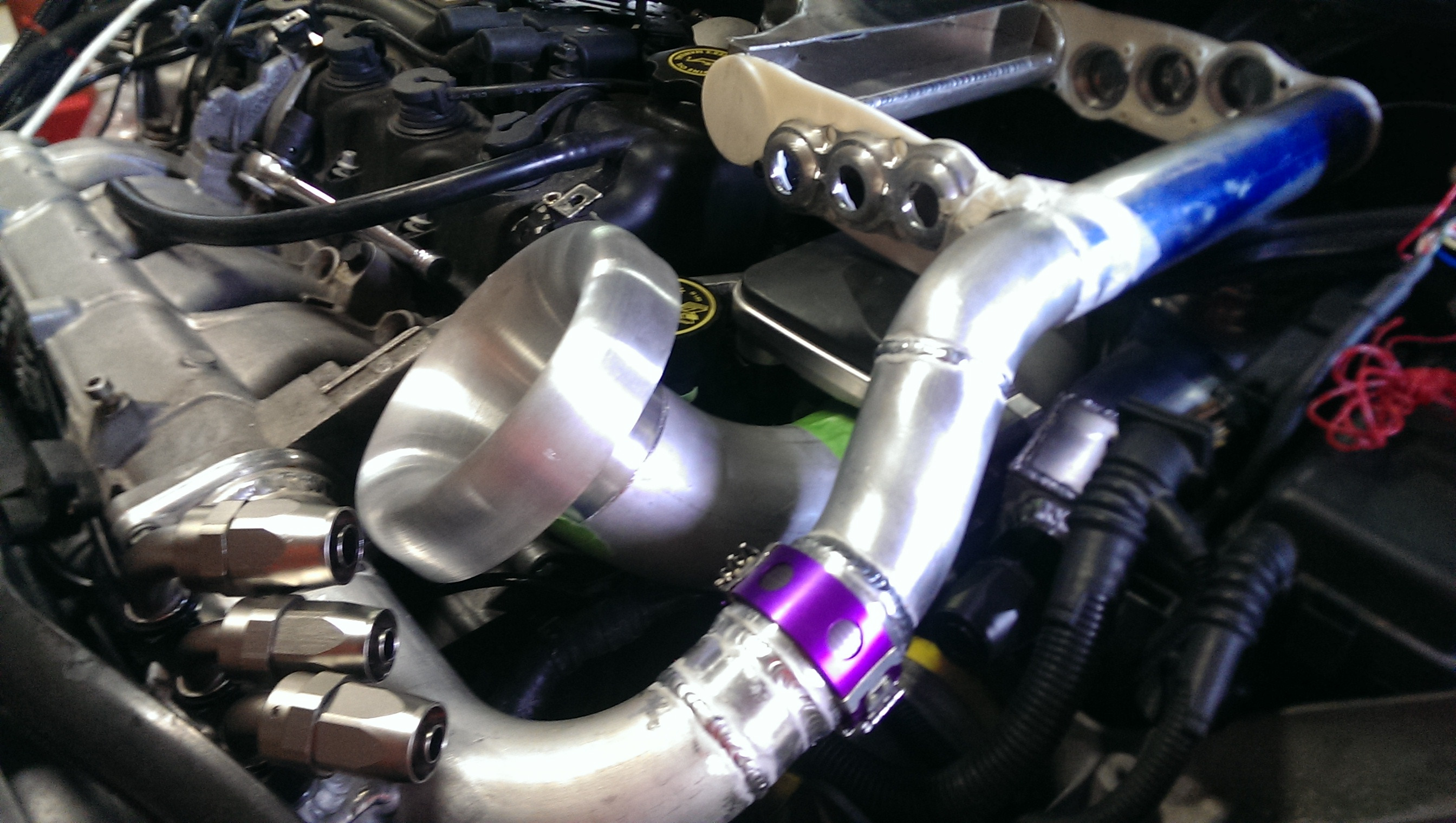
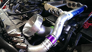
nothing to see here! nothing at all.
Please, keep moving along!

(placement of bellmouth close, but not exactly where it will be final)
(yes I am making an air filter box that will be welded to that piece of artwork)
(yes my hood scoop is now the main air intake)
(no you cannot have it  )
)

Please, keep moving along!
(placement of bellmouth close, but not exactly where it will be final)
(yes I am making an air filter box that will be welded to that piece of artwork)
(yes my hood scoop is now the main air intake)
(no you cannot have it
)