Drivetrain My build. Teaser photos and updates


Thread Starter
|
5th Gear
Joined: Aug 2008
Posts: 1,100
Likes: 13
From: Inman, SC
finished the design... somewhat...
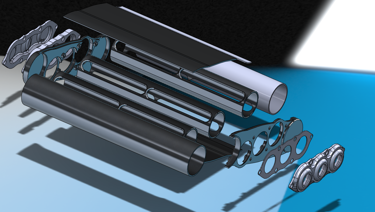
Decided to design the parts so it was as easily adaptable to multiple situations. May make some custom end plates (beyond this design) for my particular location of this intercooler, but this design could be used in any car that had the space for it.
exploded view

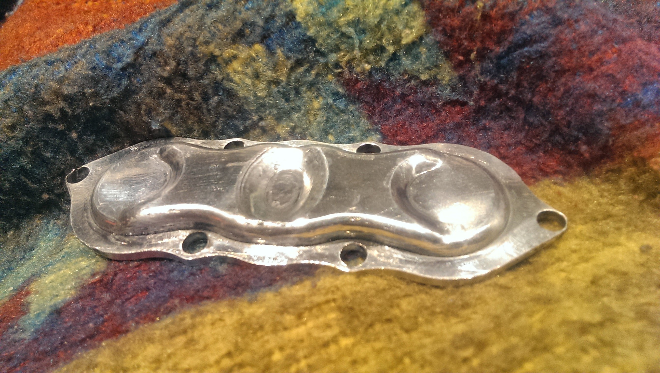
sent the parts to a machinist for quoting and he said the end plate in the back left was a bit difficult and asked if I could change it.
went ahead and helped him make some G-code, so this part came out first


The guy I contacted to make the rest of these should have a quote for me tomorrow. If it comes out to be to much $$ or to long of a wait I may just cut most of these plates on my own in free time.
This design is almost 1.5" shorter than the old one, and only requires water ports on one end.
Also is much more shallow and wider than the old design, but would even "fit" in the factory intercooler location as its height profile is only 2.5"
Decided to design the parts so it was as easily adaptable to multiple situations. May make some custom end plates (beyond this design) for my particular location of this intercooler, but this design could be used in any car that had the space for it.
exploded view
sent the parts to a machinist for quoting and he said the end plate in the back left was a bit difficult and asked if I could change it.
went ahead and helped him make some G-code, so this part came out first

The guy I contacted to make the rest of these should have a quote for me tomorrow. If it comes out to be to much $$ or to long of a wait I may just cut most of these plates on my own in free time.
This design is almost 1.5" shorter than the old one, and only requires water ports on one end.
Also is much more shallow and wider than the old design, but would even "fit" in the factory intercooler location as its height profile is only 2.5"
Last edited by soccerbummer1104; Aug 27, 2014 at 08:13 AM.
Thread Starter
|
5th Gear
Joined: Aug 2008
Posts: 1,100
Likes: 13
From: Inman, SC
yup! hit the nail on the head.
The two outer cores will have the water fed through them with the central core being on the return pass.
The water bypasses on the two outer cores will be small, but enough to bleed some cold water downstream around the outer cores for the return pass, and the bypass on the return core will be slightly larger than the outer core bypasses to alleviate some of the constriction concerns.

Thread Starter
|
5th Gear
Joined: Aug 2008
Posts: 1,100
Likes: 13
From: Inman, SC
Metal is a funny thing, especially when it comes down to how thick something should or should not be.
the structural parts of these walls are ~4mm thick. That is plenty.
the 1mm thick places on it are merely for alignment and stopping point purposes when assembling
4mm is a little over 1/8" thick. (.15")
to put into perspective,
.065" wall aluminum pipe 1.75" OD typically has a pressure rating of 550 psi!
(WOW!)
Not normally ever run that way, but none the less.
Another good example is a #10 bolt is strong enough to lift your engine out of your car (in tension)
would you be comfortable doing it? no.
Is it technically safe and fine? yes.
(#10-32 grade 8 bolt is load rated to ~1800 lbs )
)
the structural parts of these walls are ~4mm thick. That is plenty.
the 1mm thick places on it are merely for alignment and stopping point purposes when assembling
4mm is a little over 1/8" thick. (.15")
to put into perspective,
.065" wall aluminum pipe 1.75" OD typically has a pressure rating of 550 psi!
(WOW!)
Not normally ever run that way, but none the less.
Another good example is a #10 bolt is strong enough to lift your engine out of your car (in tension)
would you be comfortable doing it? no.
Is it technically safe and fine? yes.
(#10-32 grade 8 bolt is load rated to ~1800 lbs
)
I'm not worried about the structural integrity, BUT have you taken into consideration heat/expansion so that the metal wont warp once everything is hooked up and running? (I'm sure you have)
Thread Starter
|
5th Gear
Joined: Aug 2008
Posts: 1,100
Likes: 13
From: Inman, SC
as much as is possible. I have tried to make wall thicknesses as consistent as possible. Thick to thin is where most of your warping comes in. And it should not get that hot with water running through it.

6th Gear

Joined: Jan 2013
Posts: 2,257
Likes: 15
From: Dover, NH
the thermal expansions should be all that much since the temperature shouldnt change greatly, and thats what gaskets are for, granted aluminum does move the most per deg.
so long he isnt changing 200+ deg the movement is only about .008
i understand that 1/8'' alum has that pressure, just scares me a bit... and if it does break, another will just be made after it =)
so long he isnt changing 200+ deg the movement is only about .008
i understand that 1/8'' alum has that pressure, just scares me a bit... and if it does break, another will just be made after it =)
Thread Starter
|
5th Gear
Joined: Aug 2008
Posts: 1,100
Likes: 13
From: Inman, SC
Any idea where you got that figure?
My calculations have it being .0025" movement / Inch length for a 200 �F temp swing.
Means thickness wise I am looking at .00125 of growth and length comes in at
.01"
My calculations have it being .0025" movement / Inch length for a 200 �F temp swing.
Means thickness wise I am looking at .00125 of growth and length comes in at
.01"

6th Gear
Joined: Jan 2013
Posts: 2,257
Likes: 15
From: Dover, NH
you didnt learn this in highschool =) mechanical engineering
i was more thinking of my project at work, we have a .0015 interference fit for a part. and cooling a diam of 2.951 to -321 with LN would give .014 of movement
never actually did math for yours, glad you did tho!
i was more thinking of my project at work, we have a .0015 interference fit for a part. and cooling a diam of 2.951 to -321 with LN would give .014 of movement
never actually did math for yours, glad you did tho!
Thread Starter
|
5th Gear
Joined: Aug 2008
Posts: 1,100
Likes: 13
From: Inman, SC
kind of a nature of habbit! haha.
I am a chemical engineer by schooling, but do a good bit of mechanical engineering and prototyping work as well as when we are trying to process something and work and cannot, while some other chem-e's call in a mech-E to help them come up with something to get around it, I got tired of that and just started making things myself! haha.
After all, A chem-E is just a glorified Mech-E with a slight chem background
but a lot of what we deal with at work is extruder barrels and screws that need to not bind when they heat up so we worry about thermal expansion and leaving slop in the right places to let some things move, and other things not.
I am a chemical engineer by schooling, but do a good bit of mechanical engineering and prototyping work as well as when we are trying to process something and work and cannot, while some other chem-e's call in a mech-E to help them come up with something to get around it, I got tired of that and just started making things myself! haha.
After all, A chem-E is just a glorified Mech-E with a slight chem background
but a lot of what we deal with at work is extruder barrels and screws that need to not bind when they heat up
so we worry about thermal expansion and leaving slop in the right places to let some things move, and other things not.
Thread Starter
|
5th Gear
Joined: Aug 2008
Posts: 1,100
Likes: 13
From: Inman, SC
decided to change welding tracts a little and do some aluminum again. Phew, I need to get a little more practice in, but they didnt turn out to bad.
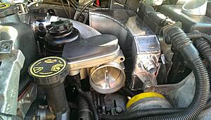
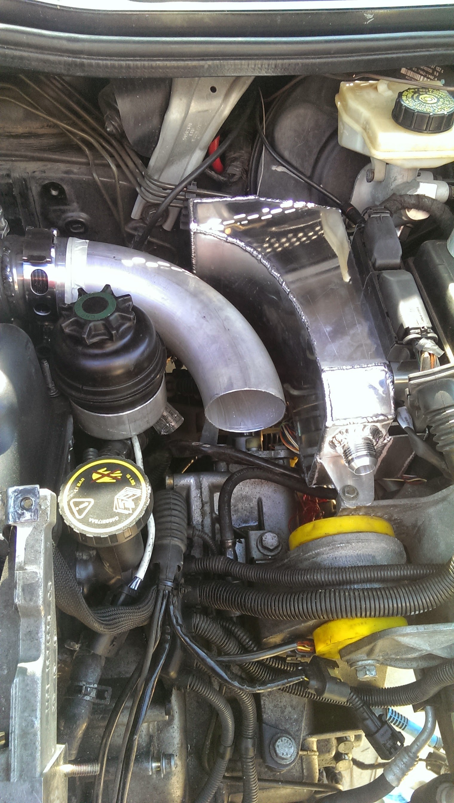
But I decided to make the W2A reservoir tank. Still have to put in a filler cap as well as the outlet bung, but I need to order those first.
Holds .78 US GAL.

It also doubles as the ECU bracket, shown on the right here, and this is showing the rough proposed location of the power steering resevoir and throttle body. I may move the PS resevoir up next to the drivers head lamp and rout cables around the transmission though. Not sure yet.
But I decided to make the W2A reservoir tank. Still have to put in a filler cap as well as the outlet bung, but I need to order those first.
Holds .78 US GAL.
It also doubles as the ECU bracket, shown on the right here, and this is showing the rough proposed location of the power steering resevoir and throttle body. I may move the PS resevoir up next to the drivers head lamp and rout cables around the transmission though. Not sure yet.

Thread Starter
|
5th Gear
Joined: Aug 2008
Posts: 1,100
Likes: 13
From: Inman, SC
Well generally you want your reservoirs and fill points to be at the highest locations so that you can keep the system filled and not have water poori.g out. Haha. Unfortunately this is not possible for this since the intercooler will actuallw be directly over this tank, but it is the best I could do without putting the tank over the turbo. (Which is acting happy where I may have to put coolant overflow :| engine bay is going to be tight . OEM tight. Haha.
6th Gear
Joined: Jan 2013
Posts: 2,257
Likes: 15
From: Dover, NH
very tight! may beeven be tighter since you have more stuff going in and thats right that you are keeping the intercooler in the same position. is there going to be a front mount for the w2a cooling?
Thread Starter
|
5th Gear
Joined: Aug 2008
Posts: 1,100
Likes: 13
From: Inman, SC
There is.
You can see pictures of it on earlier pages in the thread.
Started as the w2a radiator from a 03 SVT cobra (OES was garrett)
And I re-made the end tanks.
If it doesnt work I will probably just get a Bell core and weld it up myself
You can see pictures of it on earlier pages in the thread.
Started as the w2a radiator from a 03 SVT cobra (OES was garrett)
And I re-made the end tanks.
If it doesnt work I will probably just get a Bell core and weld it up myself
Thread Starter
|
5th Gear
Joined: Aug 2008
Posts: 1,100
Likes: 13
From: Inman, SC
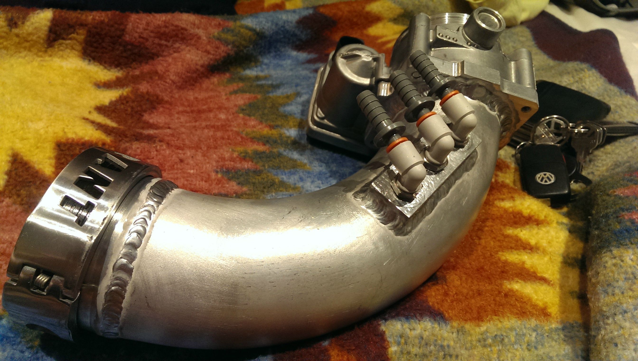
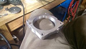
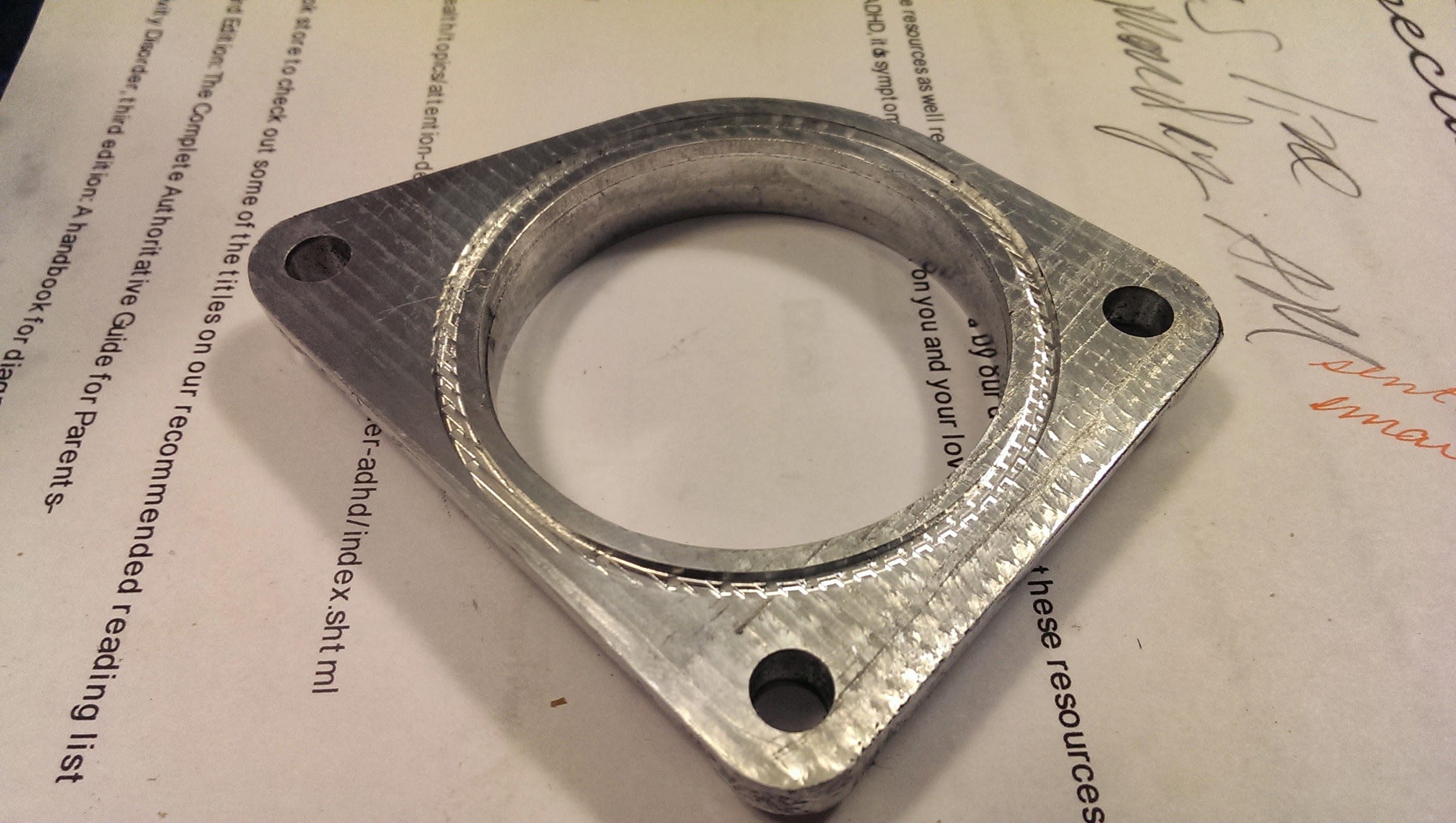
okay, well, I needed some adapter plates,
So in true "me" fashion I dimensioned them and then drew it up in solidworks and got to cutting!
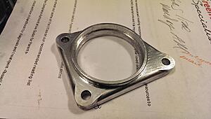
Needed the flange to connect to the stock intake manifold, as well as one for the new 76mm throttle body.
anywho, after cutting away the support, this was the first test fit on the intake manifold

As you may be able to see through the potato lens, the fitup is pretty spot on.
little better photo of the outside
The lip inside was to line up the transition cone perfectly and give a smooth flow path.
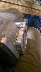
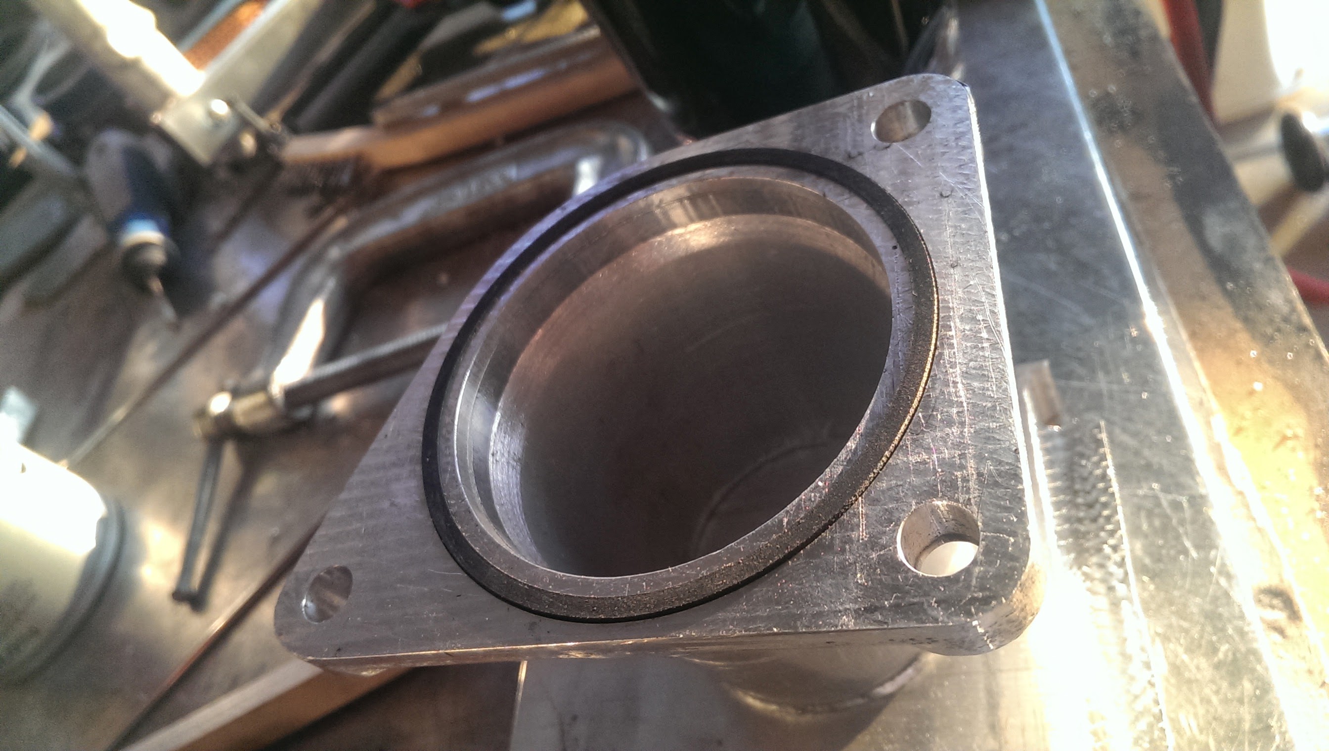
And here is where I took a small amount of design licencing and added in an "upgrade" to the stock piece.

It now uses a square o-ring for sealing vs a gasket.
This should be leak proof up to 260psi (a bit overkill eh?)
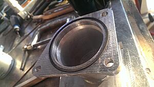
o-ring test fit -> spot on.
then I welded on the transition cone to bring it down from 2.5" to 2" (the size of the intercooler outlet)
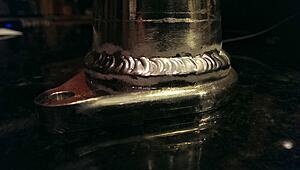

snug as a bug!
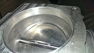
next up is the throttle plate!
Complete with locating pins and a nifty S profiled wall on the inside!!
the S profile is because the throttle body ID is 76mm (~3") while the tubing is 3" OD, so I needed to taper the hole by .125" D (.065" radius decrease)
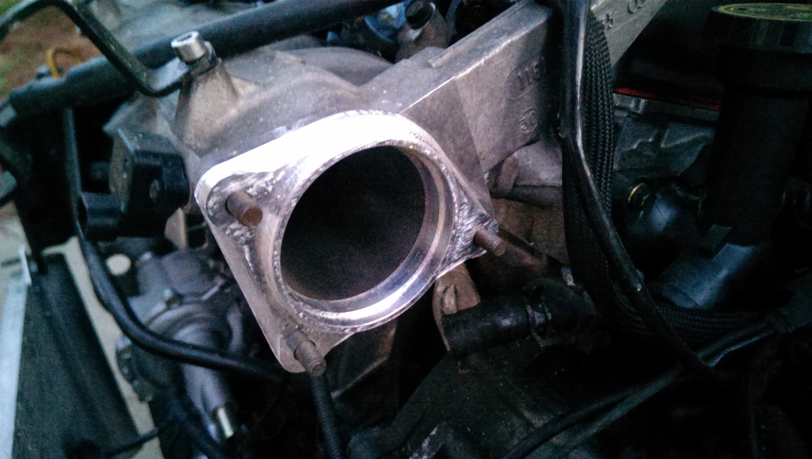
but she fits up nicely!

mmm. that transition!
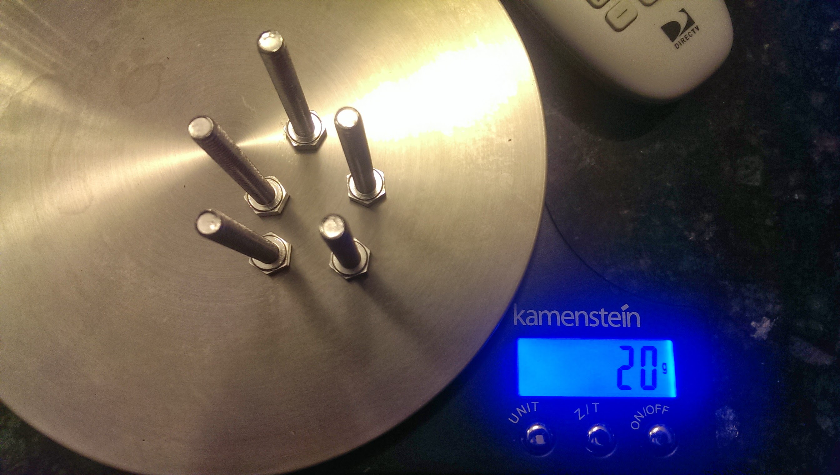
And then to hold it on I decided to buy something that tickled my fancy the other day on mcmaster carr.
So... standard bolt made from steel:

the ones currently holding the throttle body on... LOL!

they are made from 2024-T4 aluminum. rockwell hardness of B40 and a tensile strength of 37,000 PSI (fail around 5,600 lbs of pull force on the bolt) (the same as most standard mild steel bolts) but they weigh a good bit less!
So in true "me" fashion I dimensioned them and then drew it up in solidworks and got to cutting!
Needed the flange to connect to the stock intake manifold, as well as one for the new 76mm throttle body.
anywho, after cutting away the support, this was the first test fit on the intake manifold
As you may be able to see through the potato lens, the fitup is pretty spot on.
little better photo of the outside

The lip inside was to line up the transition cone perfectly and give a smooth flow path.
And here is where I took a small amount of design licencing and added in an "upgrade" to the stock piece.
It now uses a square o-ring for sealing vs a gasket.
This should be leak proof up to 260psi (a bit overkill eh?)
o-ring test fit -> spot on.
then I welded on the transition cone to bring it down from 2.5" to 2" (the size of the intercooler outlet)


snug as a bug!
next up is the throttle plate!

Complete with locating pins and a nifty S profiled wall on the inside!!
the S profile is because the throttle body ID is 76mm (~3") while the tubing is 3" OD, so I needed to taper the hole by .125" D (.065" radius decrease)
but she fits up nicely!


mmm. that transition!

And then to hold it on I decided to buy something that tickled my fancy the other day on mcmaster carr.
So... standard bolt made from steel:

the ones currently holding the throttle body on... LOL!
they are made from 2024-T4 aluminum. rockwell hardness of B40 and a tensile strength of 37,000 PSI (fail around 5,600 lbs of pull force on the bolt) (the same as most standard mild steel bolts) but they weigh a good bit less!
 lol
lol