
How To Electrical :: AutoMeter Boost Gauge Install


It's a royal pain having to take the IC off to check for a loose connection. I recommend you check out the install instructions on Alta's website for their new R53 gauge set up. They show a much more accessable hose to T into.


3rd Gear
Joined: Sep 2007
Posts: 239
Likes: 1
From: Houston, Tx
Don't know if this has been mentioned but....
I am a tall guy and climbing under the dash of my MINI was very hard. But I found the grey/red wire down by the drivers seat. I pulled the plastic panel that goes from the fuse box down the side of the drivers seat on the inside of the car. There is a junction where alot of the grey/red wires come together coming out of the harness just in front of the drivers seat under the plastic cover. I just taped for power there and it works with the dimmer.
I am a tall guy and climbing under the dash of my MINI was very hard. But I found the grey/red wire down by the drivers seat. I pulled the plastic panel that goes from the fuse box down the side of the drivers seat on the inside of the car. There is a junction where alot of the grey/red wires come together coming out of the harness just in front of the drivers seat under the plastic cover. I just taped for power there and it works with the dimmer.
At any rate I did the same. picked the wire tried it with a multitester with the dimmer and use an inline wire splicer from harbor frieght. No wire caps, no soldering and a boost gauge that dims. over all im pleased.

ok i have a few questions....
1. the back of the guage has two long screws coming out of it....i noticed when i put the guage in the cup the screws make the guage stick out....where these grounded down or is there a way to move them?
2.the light socket with the power and ground wires is awfully short...did any of you butt connect longer wire to be able to find the proper wire spots for tapping?
3. is it less of a hassle to remove the intercooler and tap into the FPR or the alta way?
2) Yeah I just crimped some wire connectors in there that I had from my old RC car racing days. I think either butt join the wires or just using some connectors from radio shack or something would be the ticket. I like the connector Idea so it's easy to remove and put back... although for what reason i don't know.
3) Way tells me that the way alta states it is easier. I think that way might be better because you can spot check the connections and see if they are loose. I actually had mine come loose once so i took it all apart and zip tied the 3 sides of the T connection. Since then it is rock solid. I think if you remove the IC and T at the fpv... def use the smallest size zip ties to secure the lines.
hope this helped.
Actually I'm sure I used the T with the AM kit because the clear plastic hose that went to the gauge just fit right in there.
do you have a pic of how you routed the lines?sry if im askin alot of questions i just want to be dead sure before i start messing with the vac system...i have the guage mounted and powered and the small hose routed through the firewall....just need to be sure of the port and route for the hose
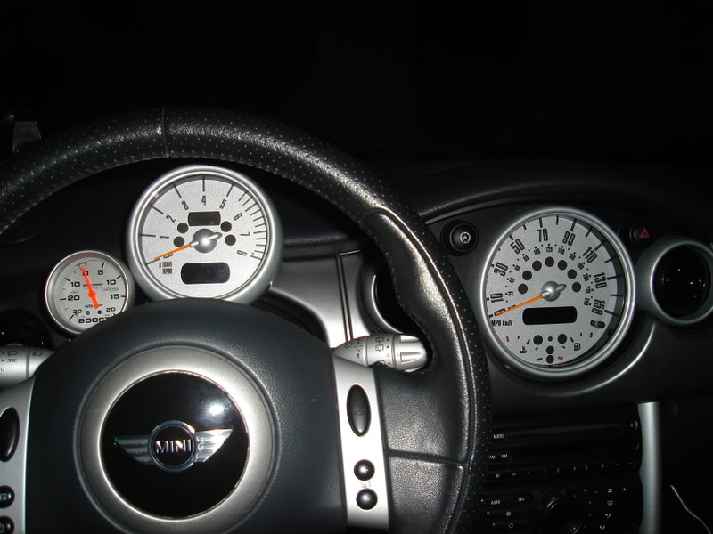
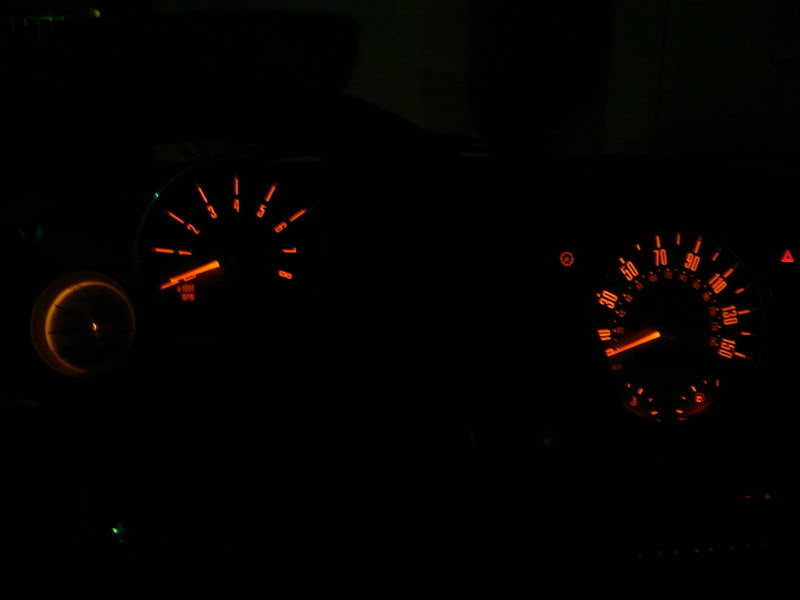
woot...i figured it out! got the sucker up and running...though i found if i didnt cut the clear tube and just coiled up the slack and hid it under the dash that tube has the flexibility to be moved around and not break!...plus i set everything up with the steering wheel all the way up! ill post a pic in a bit...gotta go for a shake down run

im thinking bout it...this project was more of a test to see how well i can figure out the set up...now that i have tested that it isnt all that hard im thinking of trying another one but we will see...now i think i may add one or maybe two other things and then get it tuned

http://www.minspeed.net/BGT.htm

Last edited by Bahamabart; Jan 26, 2008 at 05:10 AM.
actually i used a standard 3/16" T fitting for the intake manifold hose modification and 5/32" hose....routed the 5/32" hose all the way up near the rubber gasket punch point and used a 3/16"-1/4" adapter(so i can attach the 1/4-1/8" reducer)...since i dont have that plastic 1/8 vac hose strung out so far there isnt any strain on it and so far even with adjusting the steering wheel ive had no kinks or breaks...
actually i used a standard 3/16" T fitting for the intake manifold hose modification and 5/32" hose....routed the 5/32" hose all the way up near the rubber gasket punch point and used a 3/16"-1/4" adapter(so i can attach the 1/4-1/8" reducer)...since i dont have that plastic 1/8 vac hose strung out so far there isnt any strain on it and so far even with adjusting the steering wheel ive had no kinks or breaks...
heres are some pics - I opted for using the Minspeed extended bracket. This little bracket is something I worked up w/ Peter (minspeed) to give a little more adjustability.

Of course once you add one gauge, it becomes addictive


Hook it to one side and then try the other - its simple enough.


4th Gear
Joined: May 2006
Posts: 474
Likes: 5
From: Phila suburbs
vibrating needle while driving over uneven roads
I just installed the Autometer Ultra-Lite II boost/vac gauge (reverse through the dial lighting) over the weekend and noticed while the needle is on the vacuum side, the needle will vibrate when I encounter any uneven pavement. Are any of you guys with the standard Ultra-Lite's encountering the same thing? I emailed Autometer today but haven't received a reply. I probably will just call them tomorrow.

2nd Gear
Joined: Mar 2008
Posts: 108
Likes: 0
I just installed the Autometer Ultra-Lite II boost/vac gauge (reverse through the dial lighting) over the weekend and noticed while the needle is on the vacuum side, the needle will vibrate when I encounter any uneven pavement. Are any of you guys with the standard Ultra-Lite's encountering the same thing? I emailed Autometer today but haven't received a reply. I probably will just call them tomorrow.
I have a buzz noise from mine when going from vac to boost, anyone else have this issue?
If so what have people done to correct it?

3rd Gear
Joined: Jan 2008
Posts: 279
Likes: 0
I rec'd my boost gauge today! I must have done 5-7 mods this week. I think I'm in a cult. You guys don't sell soap? Do you? JK-LOL
I removed the IC and the FPV looks like it is connected to the bottm by a wire, not a vacuum hose. Any ideas on this? I have a 05 MCS with a JCW kit and Dinan throttle body.
Thank you all for your help!
I removed the IC and the FPV looks like it is connected to the bottm by a wire, not a vacuum hose. Any ideas on this? I have a 05 MCS with a JCW kit and Dinan throttle body.
Thank you all for your help!

1st Gear
Joined: Apr 2007
Posts: 32
Likes: 0
I am making this mod next weekend and after reading all the threads here on NAM and MINI2 about this i have one single doubt about the VGS : the tube that goes into to bypass valve is already installed in the car or i need to squeeze one down there ?
