
Drivetrain BSH catch can and dual boost port install

5th Gear
Joined: Mar 2009
Posts: 857
Likes: 0
From: San Marcos, CA
It ain't under vacuum when the turbo's at full boost and the crankcase pressurizes! I use spring clamps and have had no leaks after 23K and 20psi boost. BTW, that "slight" vacuum is at 14.7psi. You don't want a vacuum leak anywhere or the ECU will go nuts. 
Last edited by Dwight Walhood; Mar 14, 2011 at 03:45 PM.


just put mine in yesterday
47e24454.jpg?t=1300139746
lol I'm still thinking if the hose would to get too hot so close to the coolant tank
47e24454.jpg?t=1300139746
lol I'm still thinking if the hose would to get too hot so close to the coolant tank
5th Gear
Joined: Mar 2009
Posts: 857
Likes: 0
From: San Marcos, CA


6th Gear
Joined: Jul 2008
Posts: 1,174
Likes: 13
From: Ohio
Yet the neck of the "in" port on my catch can has a coating of oil on its exterior up to right around where the clamp sits. Not sure if the clamp is keeping it from seeping or not, but the oil seems to want to go that way (my guess is that small quantities of oil are pooling where the hose meets the mouth of the "in" port, and capillary action is pulling it down that crack between the hose and the exterior surface of the port... but that's just a guess).
Why would I block hoses attached to my catch can?
I've flexed my extreme artistic prowess to illustrate what I was theorizing above...

That's the aim... but at the moment, just the one.
Steve that's probably a valid theory. What about the fact that the connectors that come out of the OCC have a ridge on them to seal things tight.
I know when I was putting mine on, I had to remove it a couple of times until I got just the right length of tube. Wow it was an effort getting the hoses off the connection points. I figure with the hoses just long enough to push towards each connection there's no way it could ever come off.
I know when I was putting mine on, I had to remove it a couple of times until I got just the right length of tube. Wow it was an effort getting the hoses off the connection points. I figure with the hoses just long enough to push towards each connection there's no way it could ever come off.
6th Gear
Joined: Jul 2008
Posts: 1,174
Likes: 13
From: Ohio
Steve that's probably a valid theory. What about the fact that the connectors that come out of the OCC have a ridge on them to seal things tight.
I know when I was putting mine on, I had to remove it a couple of times until I got just the right length of tube. Wow it was an effort getting the hoses off the connection points. I figure with the hoses just long enough to push towards each connection there's no way it could ever come off.
I know when I was putting mine on, I had to remove it a couple of times until I got just the right length of tube. Wow it was an effort getting the hoses off the connection points. I figure with the hoses just long enough to push towards each connection there's no way it could ever come off.

I didn't show a ridge on my catch can, though one is present. The presence of ridges (and their size/slope/etc.) probably varies quite widely, depending on which can one is talking about. My 42dd can has ridges, but it's fairly easy to work the hose over them; I wouldn't call it sufficient as a seal. (the elbow joint, on the other hand... the ridge on that thing cut a chunk out of the inner surface of a hose I pulled off of that!)
In any case, clamps... no clamps... they're a dollar or two at most and weigh next to nothing. Why not just throw them on and forget about it? They might help, and they might not... but they certainly aren't going to hurt anything.

4th Gear
Joined: Feb 2009
Posts: 347
Likes: 0
From: Chicago, IL
Ok, so I couldnt wait and just finished the install.
Like rixter said, the hardest part was fitting the right length of hose. Getting the hose off is a PITA! I put hose clamps for piece of mind, but I doubt these connections could come undone on their own....
I have just over 4300 miles on my JCW and there was already some oily deposits on every connection (the intake and sensor, and both the driver and passenger side PCV). Only time will confirm how much I (hopefully) am saving my engine?
A few questions for those that installed this with the stock airbox:
1)What is this line? Should I be worried the hose from the intake to the OCC is pushing this up higher than it was before the install? Or that it is touching the hose to the OCC?

2)Should I zip tie this area (where there was a zip tie I cut off) again? Or will it be ok without one?

Thanks for everyone's help!


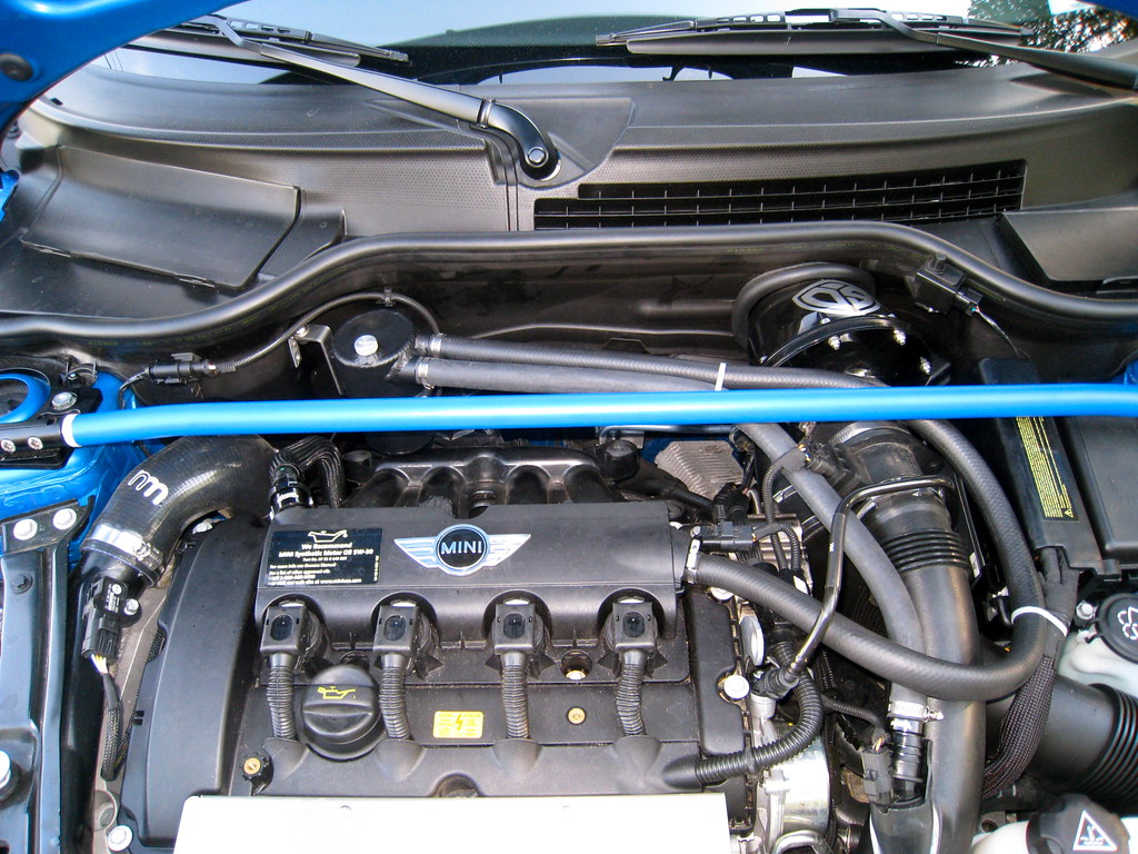
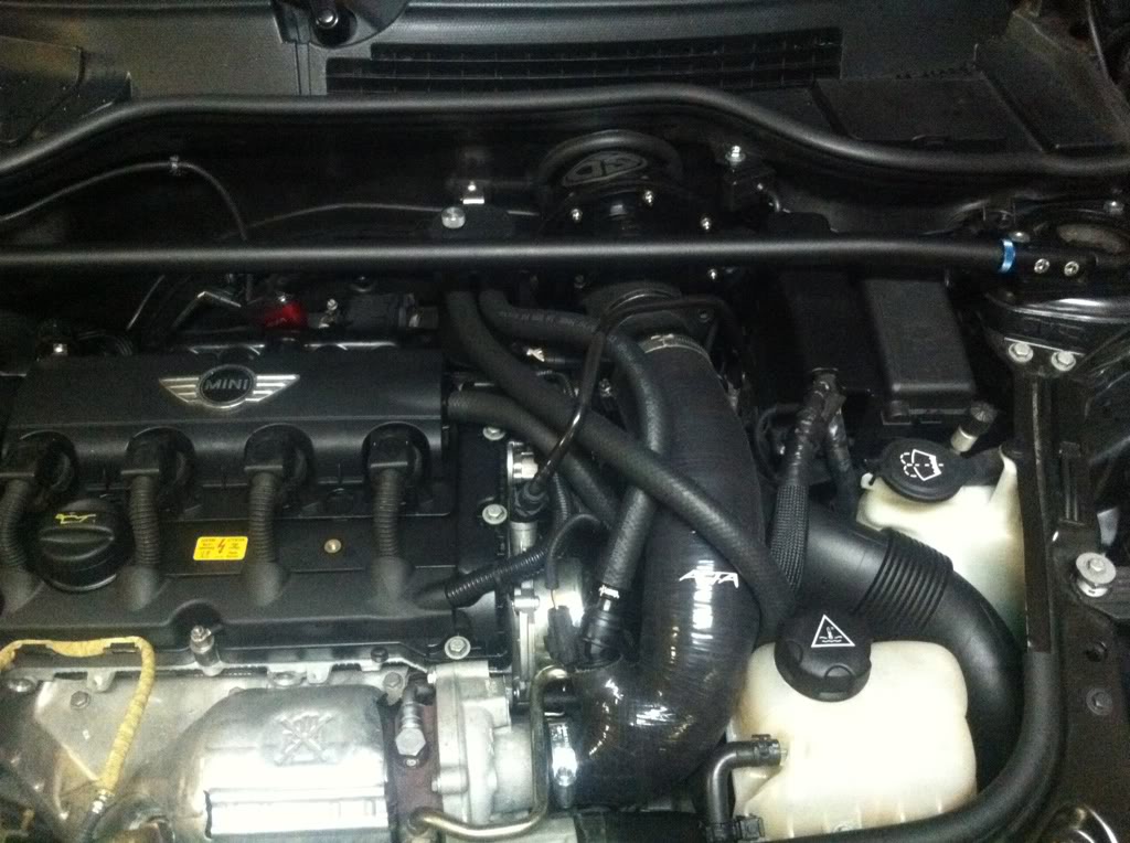
I have had the catch can on for almost a year now. Here is a picture of my engine bay.
And a picture from the first time I removed the contents of the catch can with a straw in a syringe.

And a picture from the first time I removed the contents of the catch can with a straw in a syringe.


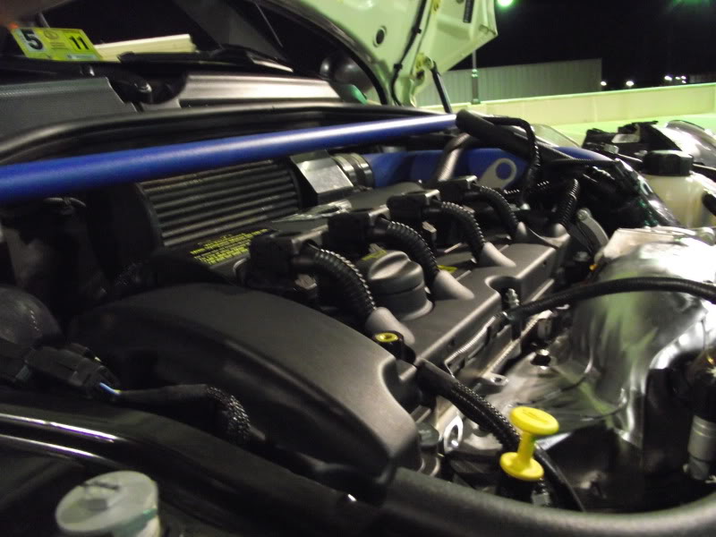
I mean pics of the catch can, cus I'm just wondering how u mounted it there? isnt the stock air pipe in that location?

I have the nm so there was no need for the extra piping which i removed, i used the included bracket to mount it to the right sub rail which passes by the washer bottle. Just a nut washer and bolt and theres alread an existing hole to mount it on. The angle gives it the slight lean back which i wanted.

Quick question: I'm picking up my car from the dealer tomorrow after having the timing chain tensioner and a few other things fixed and apparently the head tech there wants to talk to me about my catch can set up. I'm guessing about the boost port block off. The phone message I got said they were concerned this could cause future oil leaks and I'm sure they want to hold it against me somehow, like it's hurting the car. Of course I think this is without merit. Any advice on how I should handle this?
Quick question: I'm picking up my car from the dealer tomorrow after having the timing chain tensioner and a few other things fixed and apparently the head tech there wants to talk to me about my catch can set up. I'm guessing about the boost port block off. The phone message I got said they were concerned this could cause future oil leaks and I'm sure they want to hold it against me somehow, like it's hurting the car. Of course I think this is without merit. Any advice on how I should handle this?

6th Gear
Joined: May 2010
Posts: 3,260
Likes: 87
From: Pacific NW
The N18 has passages in the head, from the head cover to the intake ports. These replace the hose connection on the passenger side-rear of the head cover on the N14 engine. It was done because there was a problem with oil pooling at the throttle body on the N14 engines.
The connection from the other side of the head cover to the turbo intake, via the oil catch can, would prevent pressure from building up in the engine and causing leaks.
I talked about this with the shop Foreman at my MINI dealer. His concern was that the addition of an oil catch can and dual boost port block off is an unapproved (by the EPA) alteration of the PCV system. Though he has seen quite a few, he hasn't seen any problems caused by it.
Dave
6th Gear
Joined: May 2010
Posts: 3,260
Likes: 87
From: Pacific NW
That would defeat most of the reason for the oil catch can on a MINI, unless you put the catch can on the passenger/aft side hose, instead of on the turbo side hose, like Fishbert did. Though you would then still get oil in the turbo and aftercooler.
Really, the main advantage of the dual boost tap/block off is that with it, you don't need to install two catch cans.
Dave
Really, the main advantage of the dual boost tap/block off is that with it, you don't need to install two catch cans.
Dave

I have heard about these internal passages in the head/cover of the new N18 engine a few times now. These are the passages that do away with the passenger side PVC valve/hose arrangement as on the N14 engine.
I have a couple of questions about this. 1) Where did this information come from? 2) Has anyone actually seen them? and 3) how does this system work? I mean, do they really exist or is this just something someone was told?
One big problem I see with internal passages is... Where do you install the valve to close the system when the system is under "Boost" pressure? I have to say this idea seems a bit complicated even for BMW.
Any thoughts? Is there anything I can read that has been published on this?
Thanks

Coordinator :: Eastern Iowa MINIs
Joined: Dec 2006
Posts: 5,520
Likes: 4
From: Decorah, IA
I have heard about these internal passages in the head/cover of the new N18 engine a few times now. These are the passages that do away with the passenger side PVC valve/hose arrangement as on the N14 engine.
I have a couple of questions about this. 1) Where did this information come from? 2) Has anyone actually seen them? and 3) how does this system work? I mean, do they really exist or is this just something someone was told?
One big problem I see with internal passages is... Where do you install the valve to close the system when the system is under "Boost" pressure? I have to say this idea seems a bit complicated even for BMW.
Any thoughts? Is there anything I can read that has been published on this?
Thanks
I have a couple of questions about this. 1) Where did this information come from? 2) Has anyone actually seen them? and 3) how does this system work? I mean, do they really exist or is this just something someone was told?
One big problem I see with internal passages is... Where do you install the valve to close the system when the system is under "Boost" pressure? I have to say this idea seems a bit complicated even for BMW.
Any thoughts? Is there anything I can read that has been published on this?
Thanks