
Navigation & Audio OEM navigation upgrade-Hopefully a how-to guide.


1st Gear
Joined: Apr 2014
Posts: 12
Likes: 0
The right unknown connector (without the plastic) is for Sirius radio antenna. The left beige one is for bluetooth. If you don't have a combox you will use the bluetooth antenna connection to the head unit. If you have combox you will use the bluetooth antenna connection on the combox. On my unit this antenna is NOT connected because I have combox
1st Gear
Joined: Apr 2014
Posts: 12
Likes: 0
Combox is for the smartphone integration. It's similar to BMW without combox you get regular bluetooth connection. I believe you will need to also order center armrest if you get combox. That's where the smartphone snap in adaptor goes into.

2nd Gear
Joined: Apr 2012
Posts: 115
Likes: 7
From: Dallas area TEXAS
Great, another harness to figure out, LOL.
I do not have a combo box as I am upgrading from Boost CD to Visual Boost.
Probably explains why the Bluetooth, USB at radio aren't working.
Exactly where is the combo box or where should it be? I heard under the seat, but Passengers or Drivers?
Anyone have a pic of the combo box? If so, please include a pic of the wiring that goes into it.
Once I get one and reverse engineer it, I will post pics and wiring layout.
OH, BTW- IMPORTANT
I found out the fiber optic line from the back of the radio actually goes into a BMW fiber loop for the MOST system. It doesn't actually connect into anything except a LOOP . It terminates near passengers side right foot well computer. The wires are bright green and fiber optic.
I need to order a loop.
One step at a time. We will get this figured out by the numbers. I want to make it so easy to do, anyone could do it.
Last edited by Smoothmove; Jun 1, 2014 at 05:30 AM. Reason: grammar
2nd Gear
Joined: Apr 2012
Posts: 115
Likes: 7
From: Dallas area TEXAS
2nd Gear
Joined: Apr 2012
Posts: 115
Likes: 7
From: Dallas area TEXAS
Updates and Corrections
The Fiber optic green lines go to the Combo Box and not to the loop. Combo box controls the Bluetooth, usb function and the SAT radio somehow.
Second-
Found out the back connectors of the radio. Pic Included.
The Fiber optic green lines go to the Combo Box and not to the loop. Combo box controls the Bluetooth, usb function and the SAT radio somehow.
Second-
Found out the back connectors of the radio. Pic Included.

1st Gear
Joined: May 2014
Posts: 28
Likes: 4
Then you don't need the loop?
2nd Gear
Joined: Apr 2012
Posts: 115
Likes: 7
From: Dallas area TEXAS
Here is a pic of the missing combo box. Just picked one up for $100.
The connector on the right appears to be the Fiber Optic connector. It would make sense. It looks like it would just click in.
I didn't receive the box yet. Now, this is a theory. It just looks identical to the green fiber line.
The connector on the right appears to be the Fiber Optic connector. It would make sense. It looks like it would just click in.
I didn't receive the box yet. Now, this is a theory. It just looks identical to the green fiber line.
2nd Gear
Joined: Apr 2012
Posts: 115
Likes: 7
From: Dallas area TEXAS
Checked under both front seats and removed carpeting. There is a block of styrofoam under the carpet on each side on the floor under the seats.
Also the non connected non nav cars do not have a separate Bluetooth antenna. The BT in the boost cd is integrated.
Also the non connected non nav cars do not have a separate Bluetooth antenna. The BT in the boost cd is integrated.
1st Gear
Joined: May 2014
Posts: 28
Likes: 4
It keeps adding up with all the additional modules. Imagine it could be developed a whole lot better, but would entail less profiting.
2nd Gear
Joined: Apr 2012
Posts: 115
Likes: 7
From: Dallas area TEXAS
When you're half way thru hell, keep going.
It should be the last piece besides the Bluetooth antenna and coding
I hated the stock boost cd so much, I almost ordered another car before I tried the retrofit.
I am hitting it head on. If I had a step by step with wiring, it would be easy. There isn't a lot of info on others doing it.
It should be the last piece besides the Bluetooth antenna and coding
I hated the stock boost cd so much, I almost ordered another car before I tried the retrofit.
I am hitting it head on. If I had a step by step with wiring, it would be easy. There isn't a lot of info on others doing it.
1st Gear
Joined: May 2014
Posts: 28
Likes: 4
I went to Mini today to set up a courtesy check on the wifes mini. I asked the Techs about the wiring diagram for the Visual boost radio set. They couldn't pull it up "yet" since I didn't have mine or anothers mini scanned at the moment. Once that is up I asked for some print outs and PN's for the cabling. I am supposed to leave a note with the Job Order. Lets see how it goes.

1st Gear
Joined: May 2014
Posts: 28
Likes: 4
I think all are actually USB, with different connectors. All are 4pin correct? Most is Optical?
I got this High view diagram from the Mini guys. I plan to go back and see if I can get more. I took it from a 4 page print out and remove the Non-US country items and drew it up on Visio. The underlined items are hyper linked to something else. Another thing to gather information on.
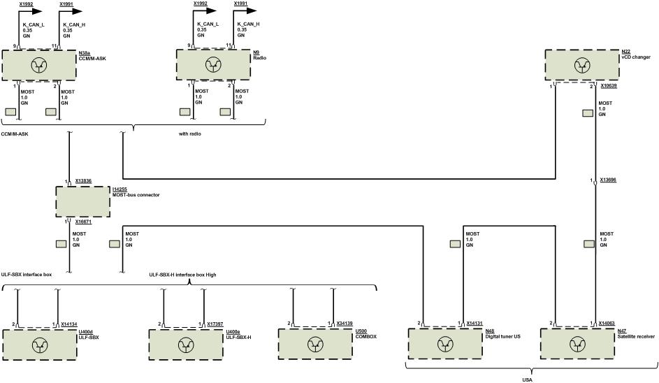
I got this High view diagram from the Mini guys. I plan to go back and see if I can get more. I took it from a 4 page print out and remove the Non-US country items and drew it up on Visio. The underlined items are hyper linked to something else. Another thing to gather information on.
1st Gear
Joined: May 2014
Posts: 28
Likes: 4
2nd Gear
Joined: Apr 2012
Posts: 115
Likes: 7
From: Dallas area TEXAS
All right, big updates. Still have not had the car coded.
Received and hooked up the combox using the two fiber optic ports coming out of the radio. Wired using a mini 26 pin harness connector, pics to follow..
Wired the can high and low as well as pos 10 and 5 amp. And ground
Bluetooth works. Antenna for Bluetooth is the beige connector on the combox.
Bluetooth phone and Bluetooth streaming audio works. Phone pairs and reads the correct VIN in the radio.
Hands free mic does not work. I have to rewire it to the combox.
The USB port does not yet work or charge the iPhone.
So far pleased that a lot of it work prug and pray.
2nd Gear
Joined: Apr 2012
Posts: 115
Likes: 7
From: Dallas area TEXAS
Here is what I have gathered, figured out or trial and error. I have the system in my car working using this as a map. Don't always rely on connector colors as Mini has changed them several times. The position of the connectors remain the same.
2nd Gear
Joined: Apr 2012
Posts: 115
Likes: 7
From: Dallas area TEXAS
other PICS. Note the differences in the early vs newer ComBox. When using the COMBOX, the Bluetooth Antenna is used at the box and NOT the radio.
The pin layouts are in this thread.
The pin layouts are in this thread.
Last edited by Smoothmove; Jun 8, 2014 at 05:30 AM. Reason: ADDING INFO
2nd Gear
Joined: Apr 2012
Posts: 115
Likes: 7
From: Dallas area TEXAS
So far, so good. My sat radio and the USB plug are the only two things not working.
The bluetooth in this thing is way better than the original boost cd Bluetooth.
The hard part is over. The wiring is all laid out for you here. The wiring I did will work for 2-2011 to present Rxx series mini coopers.
The combox I have is from a 2013 Countryman, radio is from a cooper convertible feb2012, my car build was august 2012.
2nd Gear
Joined: Apr 2012
Posts: 115
Likes: 7
From: Dallas area TEXAS
update:
Got the USB to work and Updated the Telephone software to 1006 from 1004. Multimedia still has to be updated- I am assuming thru the usb that I have not yet gotten working.
Use the BLACK port on the Combox for USB charging and data.
The WIRING from the radio to the original USB appears different and the wires were wrong in turn frying two of my memory sticks.
1st Gear
Joined: May 2014
Posts: 28
Likes: 4
What did you do/use/program to update Telephone software? With the USB cables, I was wondering what the pin layout would actually be. I am thinking the different ones would swap pins. Looks like the data and power pins are reversed. Now it will have to be determined the pin outs of each USB connection. Hope you didn't have any lost data.