When you click on links to various merchants on this site and make a purchase, this can result in this site earning a commission. Affiliate programs and affiliations include, but are not limited to, the eBay Partner Network.
I spent considerable time reviewing many offering of bung extenders. I was initially dead set not to spend $65 on the Innovate with the heatsink.
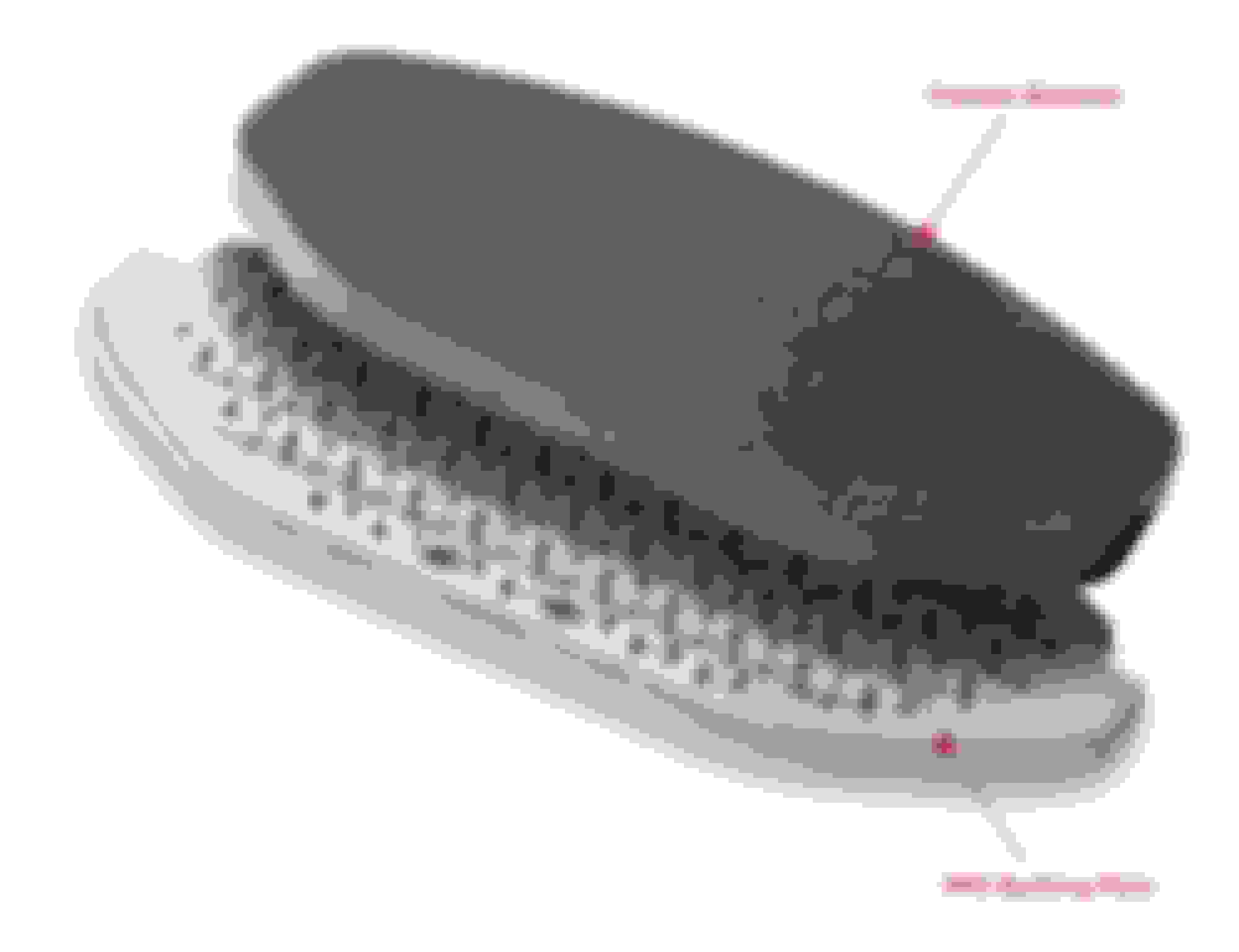
note the indexing dot on the hexagon
After a lot of thinking of all the potential pitfalls, like incompatible material, thermal conductivity, heat dissipation, fit, and most important the exhaust gas reaching the sensor and constantly being refreshed, I decided to spend $65 instead of $5 to get the job done right from the get go.
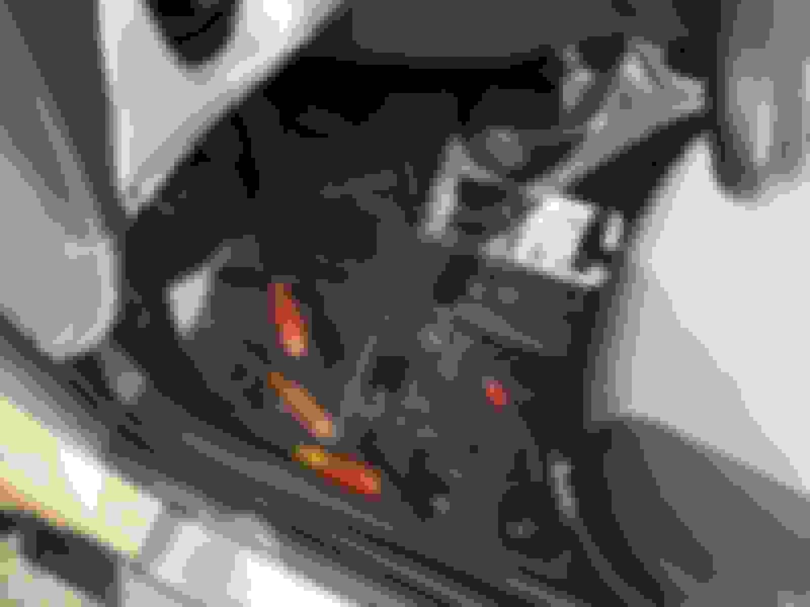
Next is to make sure the oxygen sensor + bung + heatsink extension will fit. The aggregate amounts to about 5.5 inches and there is only one possible viable spot to mount this on the stock header. It is right opposite to the stock precat sensor. Checking if there is enough clearance is easier said than done, both from under the vehicle or from the engine bay.
this photo make the check deceptively easy but it is taken with an iPhone
this is a photo that I took from under, which is also very difficult to ascertain if one can make it fit
this is the stock precat sensor on the opposite side also looking from under the car
I should note that this possible viable spot is opposite to the stock precat sensor. The section of the pipe has two length wise folded seams. Additionally it is complex shape like a vase, and it is slightly bent to provide more clearance to the stock precat sensor, thus robbing the clearance on this side just when it needs more. I could not properly check how the WB sensor assembly will or will not fit visually. I have to reach down and feel the space with my left hand. So what to do?
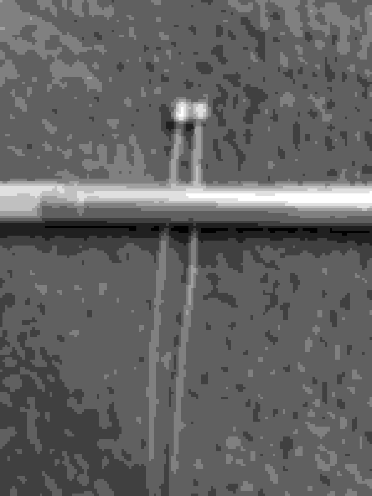
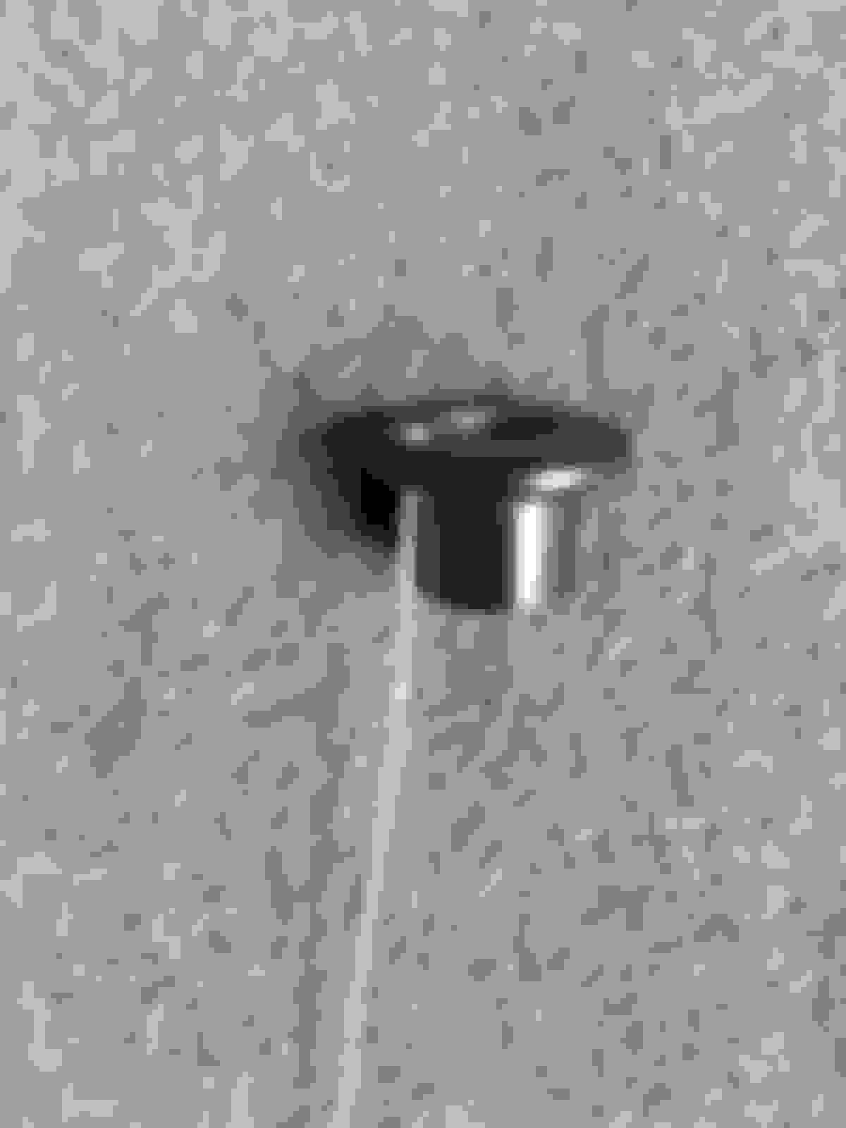
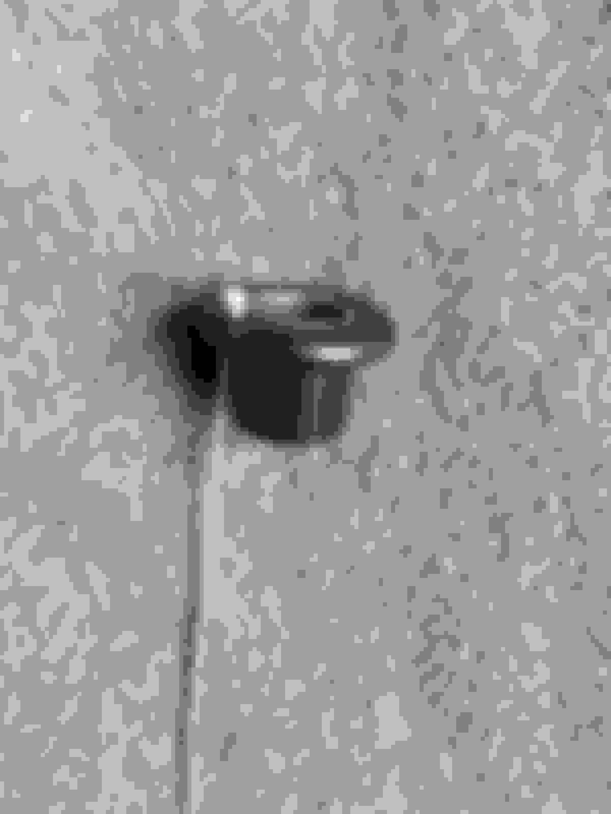
I deviced this fixture out of a departed O2 sensor, a long lag bolt, and a bung. This all to simulate the longer rigid length of the whole assembly such that I can reach down into the abyss and feel with my left hand. No looky as I did this.
To the best I can tell, there might just be one particular spot that may barely fit, and might require welding the bung slightly at an angle, in order to clear the firewall and the front sway bar at the bottom. Yes. The bloody stack sticks out 5.5 inches from the header! I still have no idea how I can determine this spot and the magic angle once the header is out. May be tag weld and then test fit trial and error.
The installation of the Innovate heatsink bung extension has a finer but critical point. The small hole on the side must face the stream of the exhaust gas. What this means is that I have to index the weld-on bung so this is align with the exhaust flow when is screwed on with the copper washer. I cannot start the work until the heatsink bung is on my hands.
The Innovate extension bung appears to be made of stainless steel, which is a metal of choice for poor thermal conductivity. The cooling fins further reduce the temperature reaching the sensor. The designed in ports promotes swirling of the gas that would otherwise be stagnant. All sounds good on paper.
shed light into many subtle things I would otherwise not know.
"It's well made. A few tips for installing. If you're bung is welded in in such a way that the dot is close, try annealing the washer. Heat it up until it's cherry red then drop it in cold water. This will make the washer 'dead soft' so you can get a little more turning out of the extender. If the extender is way off, say 180 degrees or more, if you have access to a bench grinder, grind it down until it's about half as thick, then anneal it. Also having a cheater bar to give you more leverage can help you get it right on. The flats for turning this are 22mm, btw, the same as an 02 sensor."
"Okay this is a Love/Hate review.... This spacer works, I had a sensor die in the first week of operation, and suspecting it being overheated I took a risk and bought/installed this heatsink bung - the problem went away, so that is the positive. The negative, is that you are supposed to install this bung so that the hole drilled in the side is aimed into & towards the exhaust stream and the copper washer supplied is so thick that the breather hole was 90-degrees off (it faced "up" instead of "forward"); I left it that way and the sensor still seems to be working just fine, but I would have expected for the price to have a couple different thicknesses of copper gasket so I could pick just the right shim to properly aim the hole "into the wind"."
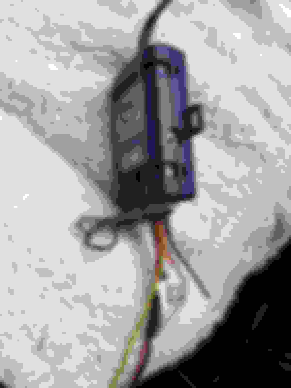
While I have the bonnet up, I remember to inspect the oil pressure switch and the plastic oil pressure line for the mechanical pressure gauge I opted to install. I checked the line during the recent track event by the feel of my left hand as you cannot see it without a camera like a smart phone.
My homemade fiber glass heat shield for the stock oil pressure switch has done its job to protect the protruded installation from the radiant heat of the header. The cable ties is badly charred. I will replace them with a few wraps of bare copper wire instead.
The made in USA plastic oil line held up just fine as it is more sheltered from the radiant heat. I took these photos at different angle so I can see the oil line's condition. I took extreme care when installing it to be sure it is free from mechanical stress and chafing when the motor rocks under hard (+/-) accelerations.
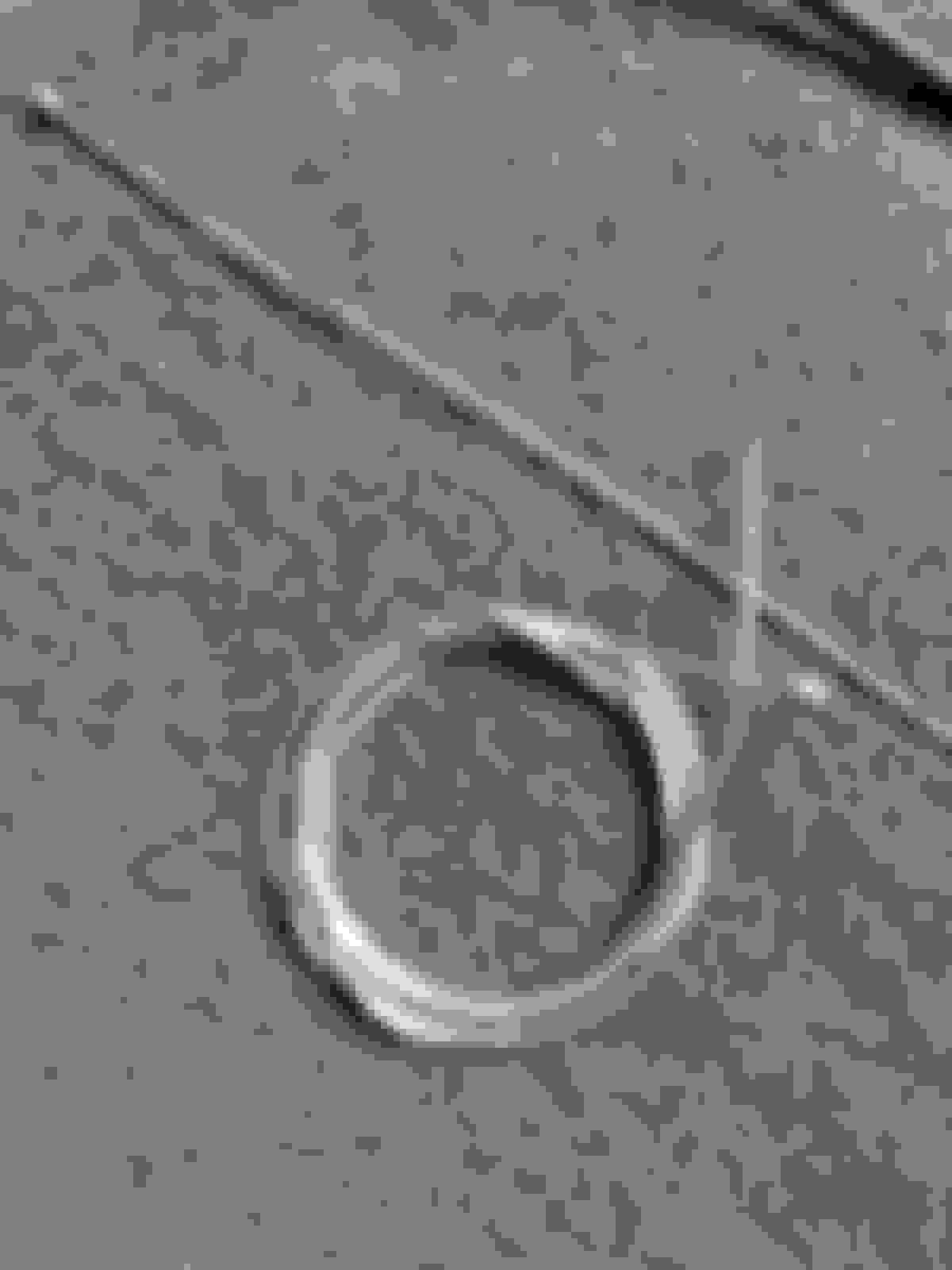
this is the first time I notice the green dots on the oil filter housing; they must be for production visual inspection aid
I have a high-flow cat. The configuration is 13" long from the cat-back flange to the edge of the doughnut flange. I have a 90% O2 extender on it that I first installed the O2 sensor in, tightened it and then the marked the orientation that I would need. I then had a shop weld everything up. I bought a used R50 manifold off ebay and have it now ready to have a doughnut flange welded on. It will also be 13" so that when inspection time comes I can do a quick swap.
On the oil pressure sensor, plan on doing that this fall along with the cat swap but did not think about the wrapping the end to protect is against the heat of the header. I plan on using a copper tube for the fluid.
It is the green connector that does not stand up to the radiant heat of one track day once the switch is moved outboard by ~ 2 inches.
I have thought about tapping the filter housing. With the exhaust manifold moved out of the way, that I can do when I change to the stock cat setup, the filter housing is pretty easy to access.
I have thought about tapping the filter housing. With the exhaust manifold moved out of the way, that I can do when I change to the stock cat setup, the filter housing is pretty easy to access.
Tapping the filter housing may be quite difficult to find a spot that lend itself to the tubing routing. By looking at the photos of the filter housing you don't know all the constrains around it. You would want the tubing exit vertically very similar to what I did. The angles that work is very limited even with the Cravenspeed T-adapter.
I bought a Moroso T-adapter and its side port is 1/4" closer to the male thread and that feels crammed for the brass fitting, making it a bit too close to the oil filter.
There are some old threads about tapping the housing. Would use a 90 and thinking that there would be a short stub and then another 90 to get the piping up onto the firewall/wiper area shroud. Might even be able to find a flexible stainless hose.
I was going to do something similar but the idea distilled down to my final version, being simplest and least fittings. That US made plastic tubing is very tough. The biggest enemy is excess heat. I think it is less failure prone than metal tubing.
I've got a lot of Mini gifts in the transit pipeline. I am postponing putting Mini up on jack stands until these parts arrive as Mini is afraid of height. Not sitting idle here. Made some progress on preparing the electrical wiring for the ByteTronik Miniport and the Innovate MTX-L plus A/F gauge. First is to deal with the fokking door on the ODB port. I spent 2 good hours trying to save from breaking the hinges.
finding a grommet for the WB oxygen sensor cable through the sheet metal
found one
this is the ODB port door that I tried to save from breaking
undoing these two Torx screws are not as easy as it seems
it is a misery working at the ODB port due to the awkward location
I even removed the Euro parcel shelf and that didn't help
Someone over at Minitorque said it best. Just snap off the fokking door, and that was what I ended up doing while trying to pry out the hinges.
next is to deal with the Y-ODB cable; this is the only one that I could find that has all the necessary pins routed; it is too short to get to the Euro parcel shelf where I planned to place the ByteTronik Miniport
the broken hinges ain't so bad ; my Mini now has a blemish
next is to modify the poorly design stainless steel clip so the connector will not fall down from gravity
success!
next is to modify the Y-cable to make it longer, but not too long
this was time consuming but has to be done
this has to be a joke - "R52 GBOX" sticker
up to two ODB devices on the Euro parcel shelf
next to test the cable to make sure all is well
next I finished off the brace for the very limited edition JCW gauge pod
the Innovate MTX-L Plus will be mounted here
removing the face plate trim ring of the Alpine head unit so I can tap into the +12V power for the Innovate A/F gauge; it can be a real ***** to remove but I am getting very proficient
Fill the gaps. I don't care about filling the gaps in the wheel wells. I do care about filling the gap inside the wheel barrels, especially the front paws as Mini's well being depends heavily on them.
the set of BP-30 from Quebec arrived exactly like the fleaBay photo
looks semi-metallic
most interesting is it says NRS at the plate
Brake pads are such scams. I do not believe for a moment the production cost difference between a set of generic road pad and all out race pad are all that different. Yet the price difference is 4x and up. Charge what the market can bear is the recipe. Oh, evidently NRS makes the back plate and who know who makes the friction material for these Wilwood fancy pads. I wager Wilwood have these made by an ODM.
Hate to say it, but I can never complain about my wife shopping again after looking at this thread. We will never understand women shopping and they will never understand men with our cars . . . . .
Hate to say it, but I can never complain about my wife shopping again after looking at this thread. We will never understand women shopping and they will never understand men with our cars . . . . .
Mini is my mistress. There is another more expensive one but Mini gets all the luv.
I didn't think the PNW water had any impurities, but OK, a french woman with a necklace around her neck, wears lipstick and does not have 30 pair of heels. Ahhh, 300 maybe.
Today's small project is to prepare electrical wiring for the Innovate MTX-L Plus A/F gauge. I want to do this in the least painful way - rob and steal what I can at the head unit.
to pull out the head unit
I love this Alpine; it is simple and extremely good
I have been very unhappy with the rat nest behind the head unit. I took great pain to maintain the ability to revert back to the factory head unit. Now I don't see the point so I want to cut out a connector block to reduce the volume of the wiring harness.
I want to remove some of this bulk
One thing the A/F meter instruction warn is not to connect the dimming signal to that of the vehicle. I infer it is because most modern cars now has PWM dimming. So I pulled out the scope to check.
sure enough Mini's dimming signal for the head unit is PWM
here I reworked the harness and removed the center block of connectors that was intended for compatibility to the factory head unit - bye bye ISO connectors the rest of world doesn't use
the multi-function steering adapter that I programmed for the Alpine head unit; I also cut out a bunch of wires that is not needed for the Alpine to reduce the bulk; no plan to resell this
the volume of the rat nest is significantly reduced
I pull out switched power, ground, and dimming (just in case it works); the switch power is fused for the A/F meter
Next big job is to run the WB O2 sensor cable from the center console down to where the Oxygen sensor will be welded to the stock header. I have given a lot of thought as how best to do this, and I decided to utilize the cable cassette of the CoolerWorx shifter. I plot carefully the best spot that will not tangle with the shifter movement or chaffing.
the heat shields come out so the cable cassette of the shifter may be accessed
I took this photo of the catalytic converter; it must have 800 tiny cells
I planned to utilize the cover of the cable cassette for the WB O2 cable exit from the cockpit
a bit of trial and error to find the best spot to feed the cable under the console base into the CoolerWorx shifter
the passenger side has the least compression force on the cable
examined the shifter mechanism this is the best place for the cable exit; I want to make it such that the cover can be removed so it would be a slot instead of a hole
I thought it would be easy with this $7 Harborfreight disc cutter; it is junk
I turned to the trusty hacksaw instead
followed by some precision hand filing
getting very close; just need to smooth out the sharp edges
mission accomplished
I cannot do the actual running of the cable right up to the O2 sensor just yet as it is not possible to know where the connector should be terminated until the after the header work is finished and the WB sensor is mounted.
Though I have the CoolerWorx shifter installed for a month now, I have yet to determine if I can reinstall the two console down tubes with the shifter secured to the floor. Unlike the stock shifter the CoolerWorx have many hard points project up from the center tunnel. The shifter console trim can only be lay over the shifter vertically. Once over the base the shifter, it cannot be shift rearwards unlike with the stock shifter. I was quite sure the shifter much be unbolted from the center tunnel and lowered so the console and down tubes may be re-installed.
the down tube can easily be inserted but this is without the supporting foam base at the bottom
the black foam base for the passenger side
As the silver paint on the down tube scuffs up very easily the test has to be carried out with extremely care, making the exercise that much more difficult.
with some finesse I managed to get the down tubes and foam back in without unbolting the CoolerWorx; this saved a major PITA procedure for future maintenance
So now is to find out if my limited edition JCW gauge pod can be installed after the two down tubes are in. There are many challenges for it to tip into the two small slots that I cut into the gear shift console trim.
slide the faceplate in from the side; note that you cannot tilt the panel towards the front so to insert the two tabs into the console
by tilting it the opposite way the cigarette light is in the way
again a bit of patience and finesse it went in without 1mm of clearance to spare; you can see in this angle the panel can not be tilted back because of the angle of the plastic cover on top
finally the intended home for the A/F gauge is almost done
I am feeling good about all the serially dependency of all these piece parts. I have postponed making the final touches to finish the trims of the shifter console until these challenges are sorted. The dimensions of the JCW gauge pod cannot be 1mm larger each way. The precision CAD work upfront has paid off. Next is to drill a hole for the reverse lockout cable into the left side cupholder. Once that is done each time the floor console is remove the cable end has to be renewed by cutting off the frayed end, so shortening the jacket too.
50 cent cable
this is the cable that came with the shifter - fit perfectly
The metal head of the 50 cent cable is rough and misformed to fit into the pull ****.
clean it up with a file and it slips into the cavity but still projects a bit high
Crap! I would later realize later the switched power I tapped fro the MTX-L Plus A/F gauge is NFG . It is key position 1. Often one would be listening to music for a long time without the engine running. Unlike the DME the A/F gauge has no knowledge that the engine is not running, and it will proceed to do its things, including turning on the O2 sensor's heater. The installation instruction specifically advises not to pre-heat the sensor by delaying starting the engine.
I need to tap into ignition position 2 switched power instead. More homework.


 I still have no idea how I can determine this spot and the magic angle once the header is out. May be tag weld and then test fit trial and error.


 ; my Mini now has a blemish


 to remove but I am getting very proficient


 . It is key position 1. Often one would be listening to music for a long time without the engine running. Unlike the DME the A/F gauge has no knowledge that the engine is not running, and it will proceed to do its things, including turning on the O2 sensor's heater. The installation instruction specifically advises not to pre-heat the sensor by delaying starting the engine.