
Drivetrain Another legitimate Oil Catch Can question...


2nd Gear
Joined: Jan 2015
Posts: 105
Likes: 3
From: Florida
The single best document I have found on the topic is here: https://www.shophemi.com/images/medi..._ccv_bible.pdf
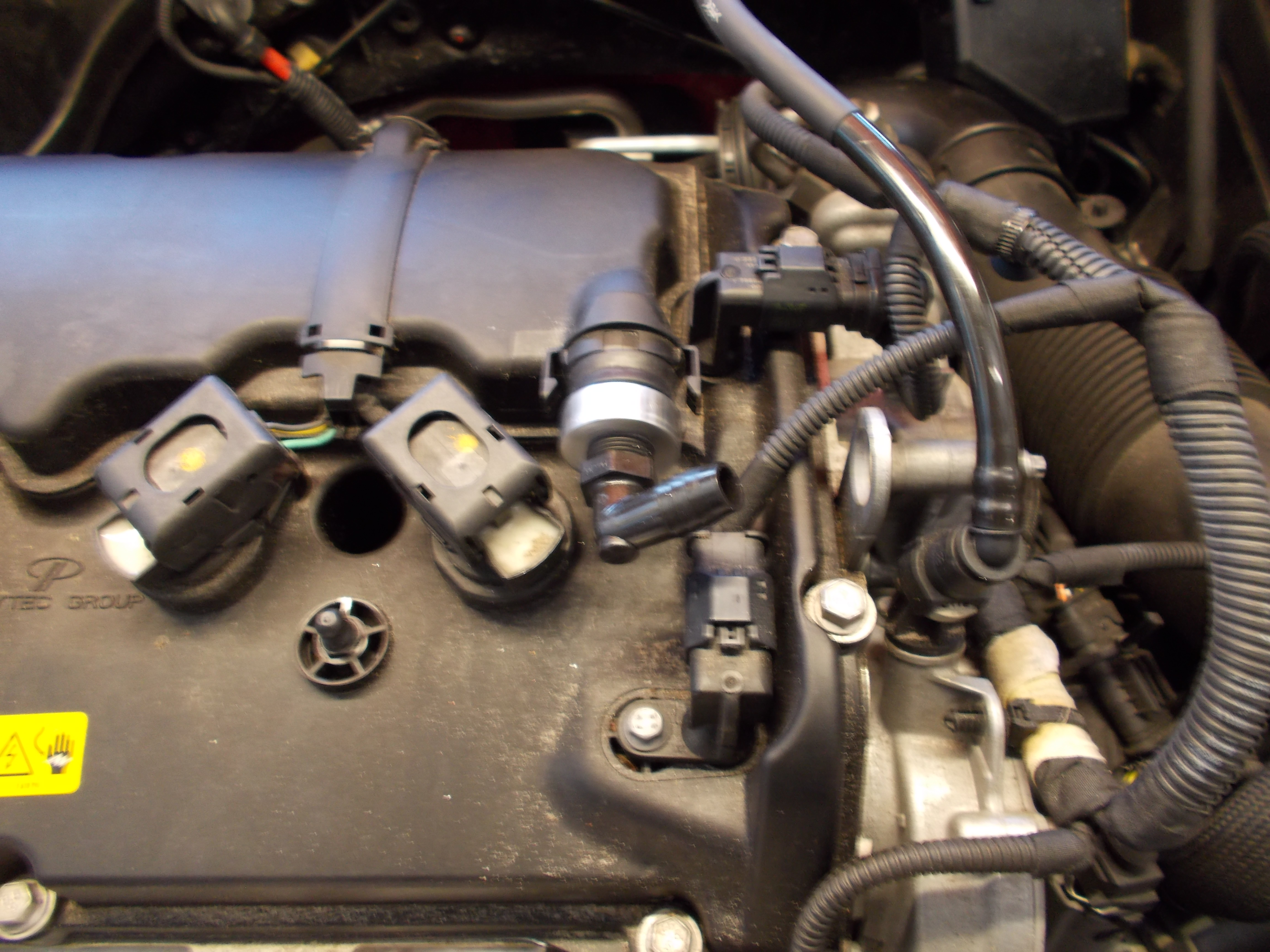
Samteezy, I think the way you described your installation is better for the N14. Blocking off the rear (passenger side) vent as in the picture seems to lead to oil consumption problems in the N14, which is explained by the doc I linked above.
I have the N18, when I installed my new FMIC last weekend there wasn't a trace of oil in the hot side pipe so it looks like the redesigned PCV system in the N18 is doing what it should.
Component Function
Ventilation Line This is the hose or tube that allows crankcase air to exit the crankcase. On some engines,
there are multiple lines that perform this function. Typically, this type of line will exit near
the top of the engine (valve cover, for example) and will have the PCV Valve in the line. It is
often connected back to a port on the intake manifold.
Makeup Air Line This is the hose or tube that lets fresh air come into the engine as crankcase air is exiting
through the Ventilation Line. On many vehicles, the makeup air line runs from the top of the
engine (valve cover, for example) to the base of the air filter or airbox.
PCV Valve The PCV valve is the most misunderstood part of the CCV system in my experience. This
valve has two primary goals: to regulate the volume of CCV air flow, and to be cheap. I put
the second goal there because it is true, and because it is the cause for some compromise
on the first goal.
Vacuum Source For the system to function properly there must be some source of vacuum to �pull� on the
Ventilation Line. In many cases, the vacuum source is a tap off of the intake manifold (which
This covers a naturally aspirated application, but the mini's I see are turbo charged, and by plugging the dirty side (the upper left corner in the picture) there is no evacuation taking place at idle, deceleration, or non-boost cruising. And then all the oil containing blow by vapors are traveling backwards, out the clean, or fresh side. So, the picture shows clean and dirty running to one can....this will stop most oil ingestion, but at the sacrifice of engine life as almost all the damaging combustion by-products are left in the crankcase to accumulate.
As in the Arrington paper (again, great paper), they do a great job of describing what each component of a PCV system does, and how it does it....so defeating evacuation defeats the constant removal of the compounds entering (the paper misses sulfuric acid and water vapor as well as abrasive carbon and soot particles) before they have a chance to settle and accumulate in the crankcase.
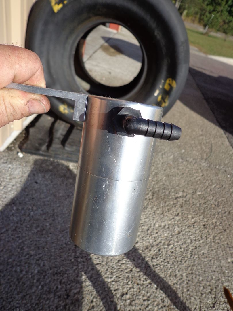
So, the proper fix for the mini as shown in the picture, is a dual valve can system that has dual outlets and checkvalves flowing away from the can inline on these outlets. The upper right corner would go to the inlet (center) of a dual valve can as this shows:
(this is a turbo 4 cylinder for the new Caddy ATS, but same principal:
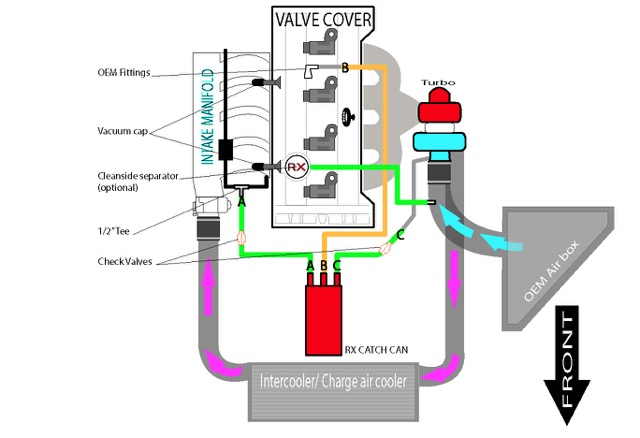
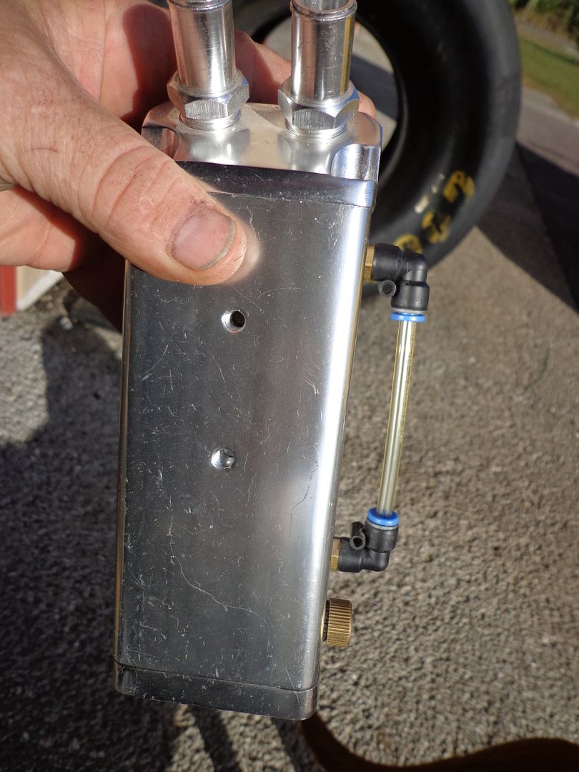
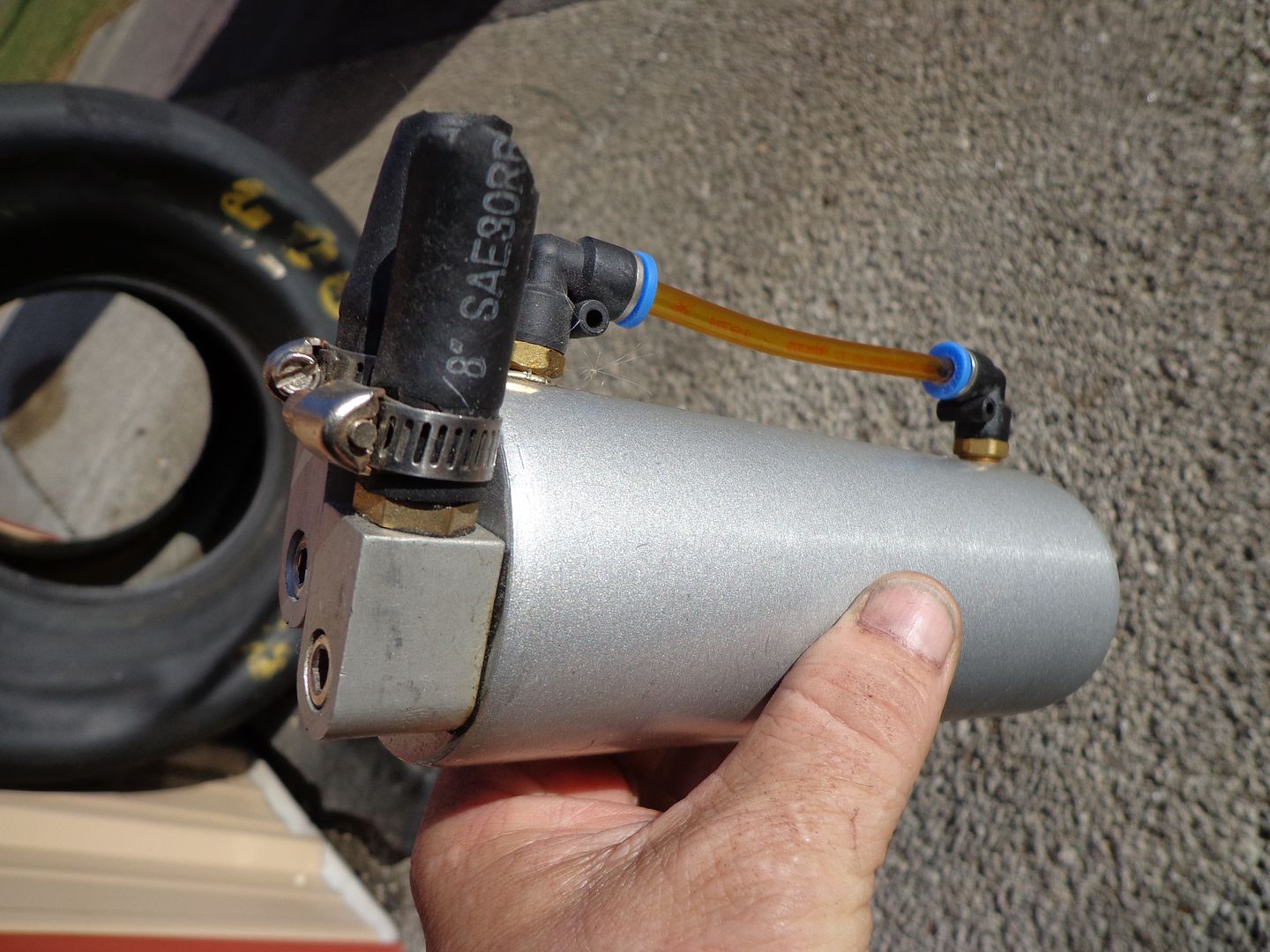
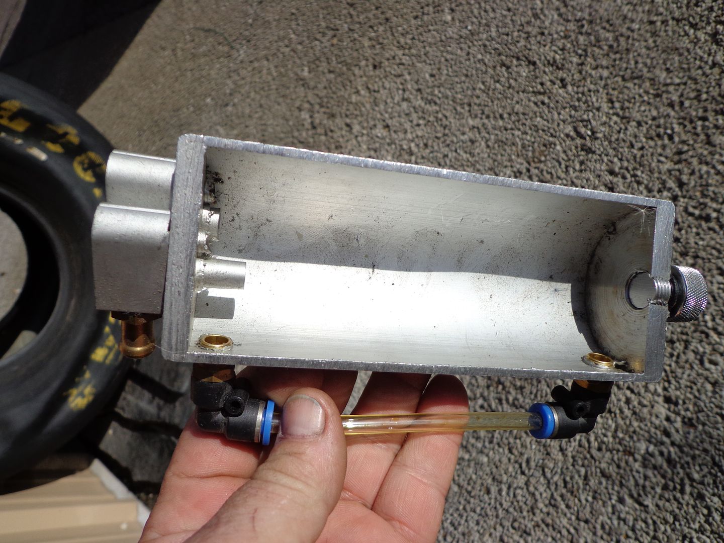
And a picture of a dual valve can showing the center inlet, outer outlets:
So, upper left corner from valve cover to center of can (inlet of foul/dirty vapors), one outlet with checkvalve flowing away from can to prevent any boost from entering the intake manifold when turbo builds boost and intake manifold vacuum is no longer present to provide evacuation, second outlet with checkvalve flowing away from the can connects to a barb you install right at the turbo inlet. You want to be as close as possible to realize the greatest suction while in boost to continue evacuating, the OEM connection is close enough for the turbo side of the fresh/clean side, the ATS diagram shows that GM has a suction port/circuit already built into the turbo inlet side for this. Then on the clean.fresh side (other end of valve cover that runs to the turbo intake tube) needs to be replaced with a clean side separator that will then connect to a -8 3/8" NPT barb you add just downstream from the MAF sensor. This maintains MAF metered air so your short term fuel trims don't go nuts trying to adapt to the un-metered air the open vented cans allow, and it maintains a closed emissions compliant system in all 49 States (CA needs CARB cert components). So, here is how the final solution will flow:
Filtered, MAF metered fresh air enters the new barb added to the cold air intake tube, runs through the clean side separator (replaces oil fill cap, and the valve cover factory barb is capped) where any oil back flow is caught, this travels through the crankcase flushing the dirty/foul vapors out and replaces them with clean filtered air. The outgoing foul/dirty vapors then run through the oil separating can, and then depending on if in boost, or if non-boost, either the intake manifold vacuum evacuates/sucks then scrubbed vapors out into the intake manifold directly, or if in-boost, the turbo inlet suction pulls it in that path where it is then pushed into the intake manifold where it can pass the valves with no compounds to coke, or bake onto the valves.
Hope this helps.
Hey, anyone with a Mini near Tampa/Sarasota that could come in for a few hours and I will install a system and video it all for others. Wont charge any labor, and then we can have a narrated video for all here.
PM me for details and to confirm.


Read most of thread. Heres my experience with carbon build up.
Without fuel washing over the intake valves, they will get carboned up no matter what!!!
I say this b/c I blasted my valves, ran 2 oil catch cans (that's what they do it catch condensation and some atomized oil) and vent to atmosphere. After 8k miles I removed the intake to find carbon built up. Its a result of the exhaust gases with some oil that works it way back into the intake during overlap. If u ever pull an intake just after a motor is shut off you will see exhaust wafting in the ports. Further. oil gets sucked down the intake guide and has a nice path to the back of the intake valve. This oily exhaust loves to adhere to a nice HOT intake valve. Not as hot as the seat and valve face as that stays hot enough to promote a carbon cutting effect. Same deal with the exhaust valves but much worse. Sucking and pulling the ccv fumes will have little to no effect on the carbon build up. Installing a meth system will eliminate this issue for the intake valves. I speak with some experience here as I was an automotive machinist for many years. Oil cans help not do not eliminate the issue.
Last edited by Indimanic; Jan 20, 2015 at 03:21 PM.


2nd Gear
Joined: Jan 2015
Posts: 105
Likes: 3
From: Florida
Read most of thread. Heres my experience with carbon build up.
Without fuel washing over the intake valves, they will get carboned up no matter what!!!
I say this b/c I blasted my valves, ran 2 oil catch cans (that's what they do it catch condensation and some atomized oil) and vent to atmosphere. After 8k miles I removed the intake to find carbon built up. Its a result of the exhaust gases with some oil that works it way back into the intake during overlap. If u ever pull an intake just after a motor is shut off you will see exhaust wafting in the ports. Further. oil gets sucked down the intake guide and has a nice path to the back of the intake valve. This oily exhaust loves to adhere to a nice HOT intake valve. Not as hot as the seat and valve face as that stays hot enough to promote a carbon cutting effect. Same deal with the exhaust valves but much worse. Sucking and pulling the ccv fumes will have little to no effect on the carbon build up. Installing a meth system will eliminate this issue for the intake valves. I speak with some experience here as I was an automotive machinist for many years. Oil cans help not do not eliminate the issue.
Without fuel washing over the intake valves, they will get carboned up no matter what!!!
I say this b/c I blasted my valves, ran 2 oil catch cans (that's what they do it catch condensation and some atomized oil) and vent to atmosphere. After 8k miles I removed the intake to find carbon built up. Its a result of the exhaust gases with some oil that works it way back into the intake during overlap. If u ever pull an intake just after a motor is shut off you will see exhaust wafting in the ports. Further. oil gets sucked down the intake guide and has a nice path to the back of the intake valve. This oily exhaust loves to adhere to a nice HOT intake valve. Not as hot as the seat and valve face as that stays hot enough to promote a carbon cutting effect. Same deal with the exhaust valves but much worse. Sucking and pulling the ccv fumes will have little to no effect on the carbon build up. Installing a meth system will eliminate this issue for the intake valves. I speak with some experience here as I was an automotive machinist for many years. Oil cans help not do not eliminate the issue.
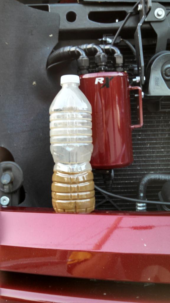
Very good post. A couple things to thnk about though, only a few cans on the market trap more than 30% of this suspended oil and other compounds (all trap some, even a soda can with 2 fittings) and that is almost no cans were designed with the critical principals to not only separate and remove the "gunk" from the PCV flow, but even those that do use some of the scientific principles ignore the Bernoulli effect, and that pulls most of any that is separated right back out the outlets to still be ingested. This is a common misconception. It is really easy for any running a can they think is doing a good job to duplicate the test I quote earlier....it is night and day obvious.
Then lets look at the reversion, or residual vapors you describe. Where does this oil come from? It is from the intake air charge contaminated first with the oil vapor due to using a ineffective separating can. If you use one of the few that DO catch and retain most all the oil, then only a small amount of fuel vapor will be present and that will not result with any coking deposits.
You can see a comparison of 2 brand new DI engines (3.6L GM) one with 70 k miles on and no can, vs 68k miles with the RX installed right from the dealer.....and 30% plus blockage with the no can, and almost no visible deposits with the other that was equipped.
Again, just look at how most cans are constructed, and you see it is impossible even with basic knowledge on flow principals to see they cannot be more than marginally effective.
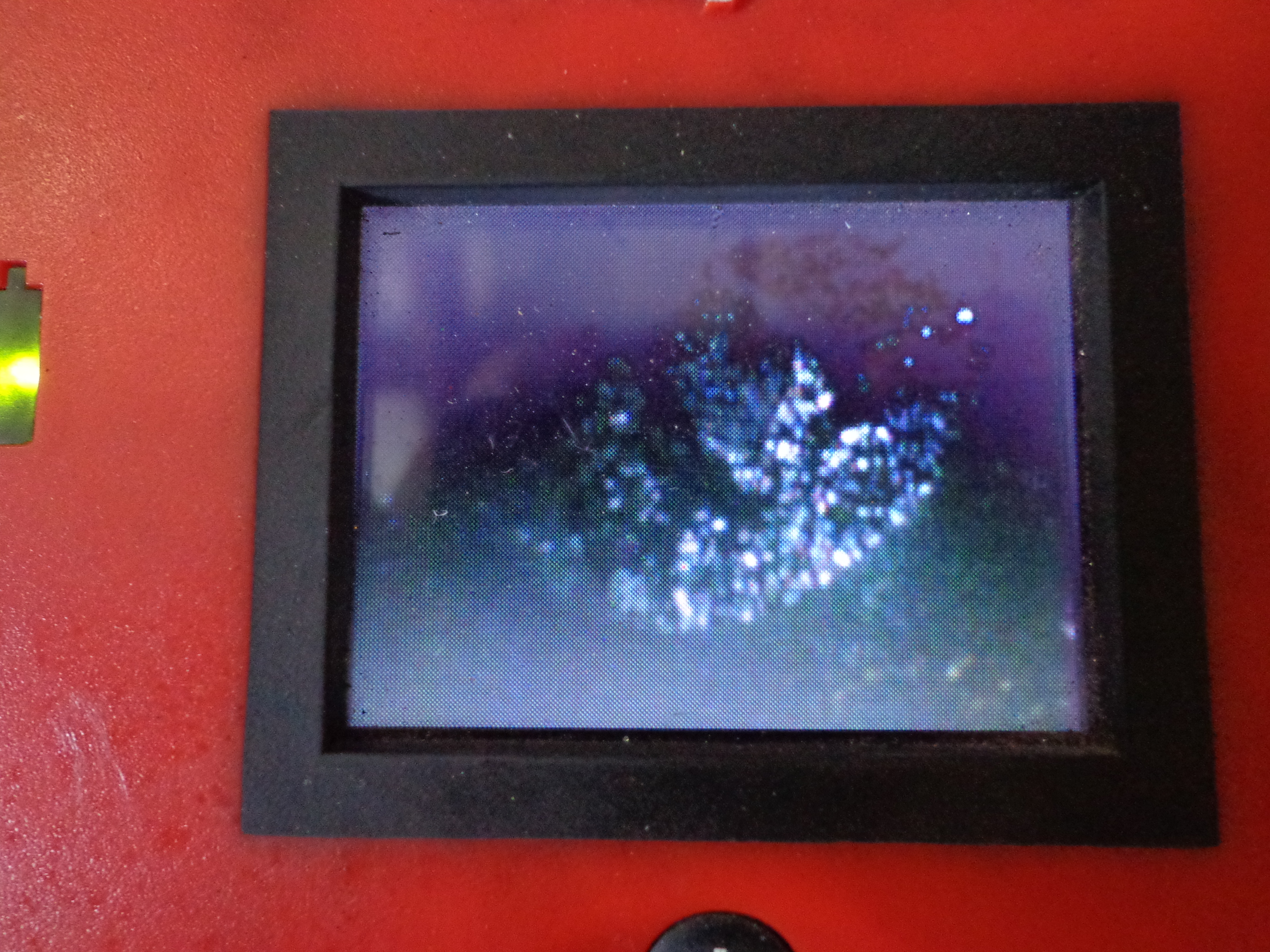
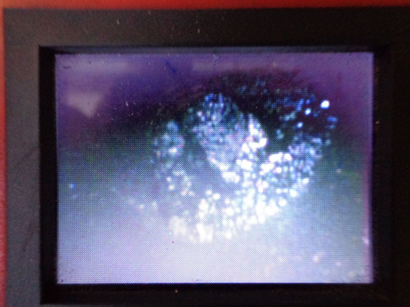
Here are valves through a boroscope (easy to do, or remove your own intake manifold and look at your own to see how severe the issue is):

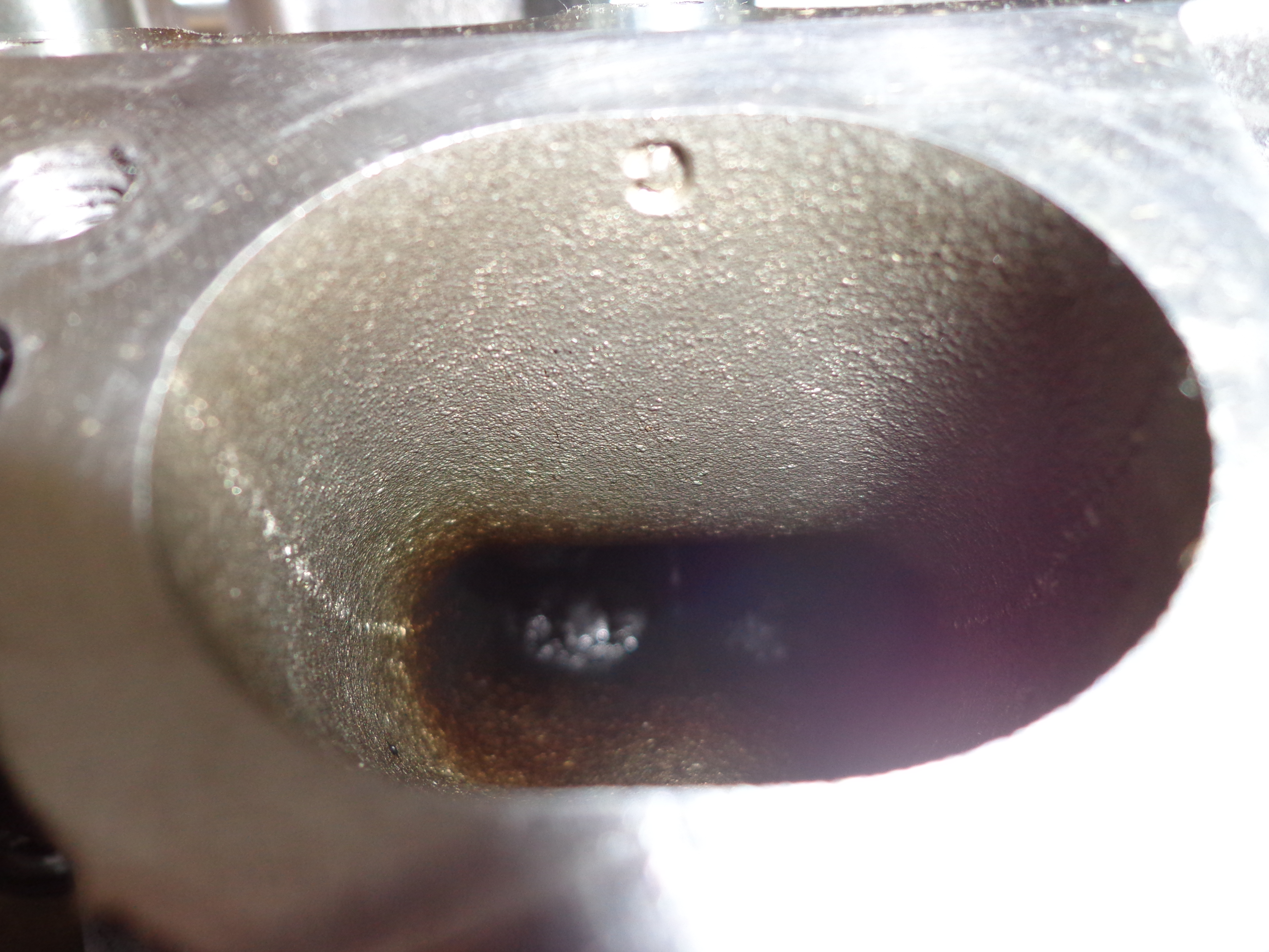
And with the intake manifold removed:
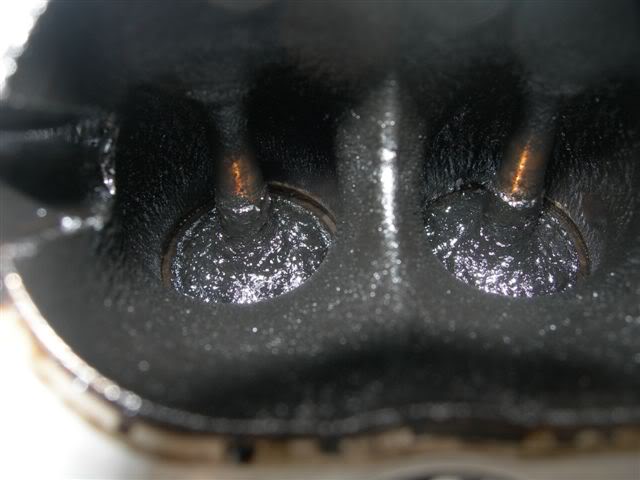
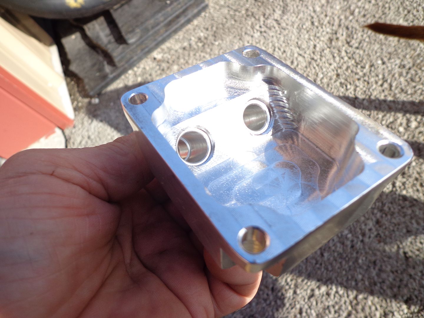
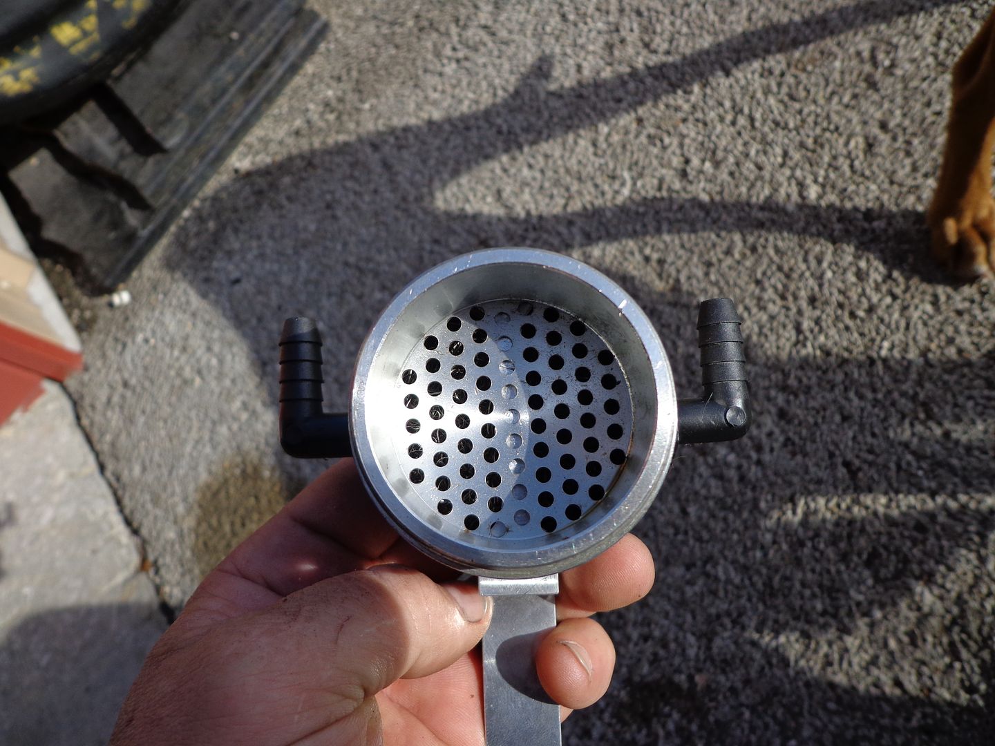
Look inside most cans..look attractive from the outside but when examined, you see there is no way most can effectively separate and retain:

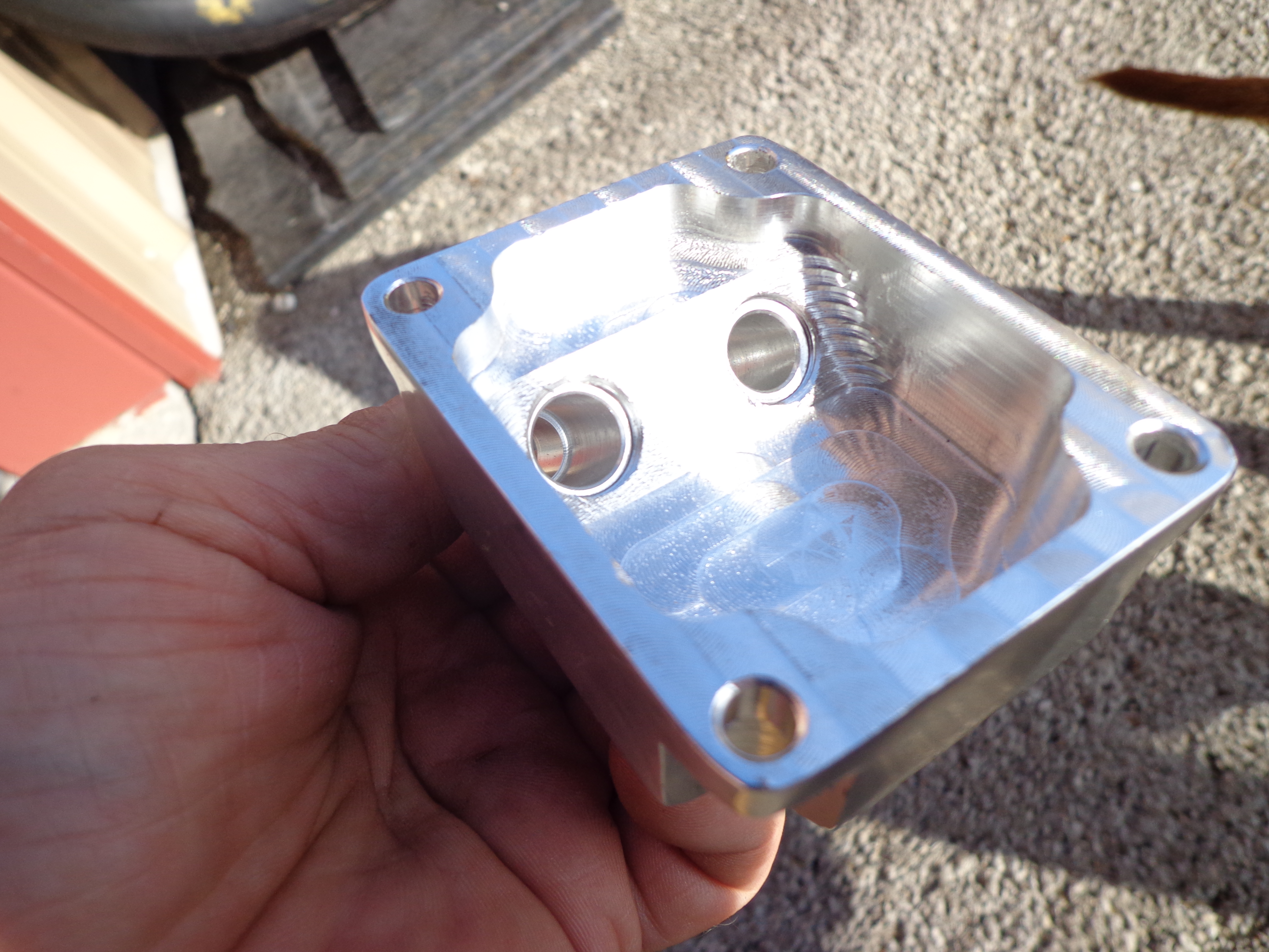
And another:


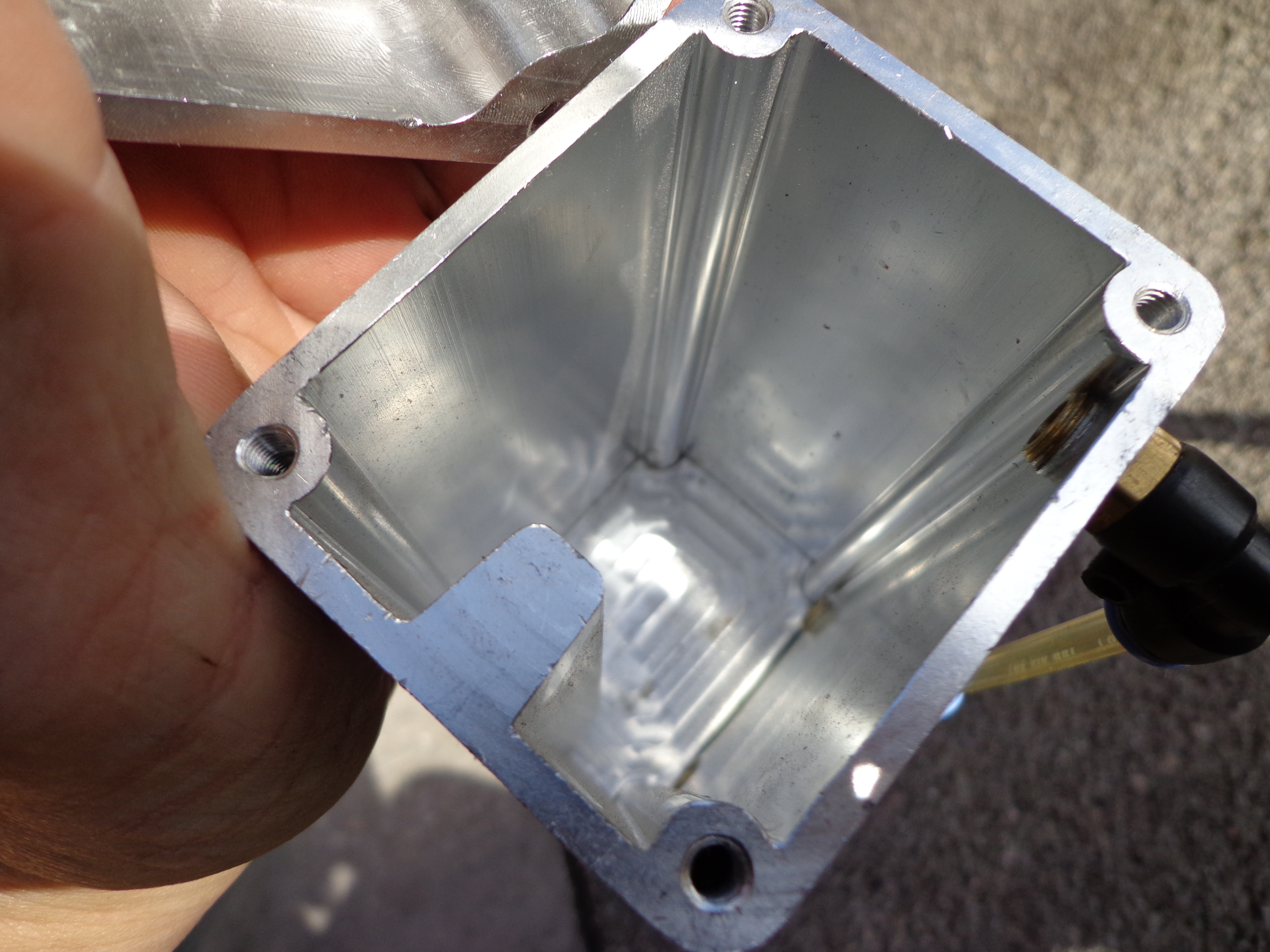
and more:


Look above, the inlet and outlet chambers are identical...both will saturate with oil in the media...fine with the inlet, but the outlet is like taking a wet washcloth and putting it to your move...now suck on it. You can't have a saturated media in the flow of the outlet without a good amount being sucked right out.
Being an Automotive Engineering and R&D firm, we have years of these we purchase, test, and cut apart to examine. Some screen, perforated material, etc. can only be partially effective. You must use several principals in a design that is effective. Coalescing, condensing, the Venturi effect, the Bernoulli effect, and gravity. Calculating the CFM of flow, and the speed, or velocity of that flow. Determine the distance from and contained liquid or any droplets that are falling from suspension and the outlet so that it isn't acting just like a soda straw and some spilled Cola on the table....put the straw near the puddle and suck...see how the liquid is pulled off the table and into the straw. Size of the main container. Any smaller than say 12 oz's and most PCV systems flow will overwhelm and "pull through" most of the liquid being caught. And more.
I can guarantee with the proper system the coking deposits are reduced to nearly nothing, and most owner have no idea what the level of degrade volumetric efficiency their engine is at with the build up. Do a Google search on BMW Direct injection intake valve coking and see the hundreds of images uploaded by BMW technicians all over the world on all the DI engines, FI or NA:
https://www.google.com/search?q=BMW+...A&ved=0CD4QsAQ
This effects EVERY DI engine in the world, but 99.9% of owners are not aware as the degradation in power and fuel economy is gradual. Just ask someone that had a manual intake valve cleaning (walnut shell blasting, etc.)
how surprised they were at the re-found power and fuel economy.
The link to the BMW images are showing all models of BMW DI engines and more.

Neutral
Joined: Apr 2014
Posts: 2
Likes: 0
From: Colorado
I don't know about video.... But I'll try to post a how to (will be my first) when I'm completed with my install.
Have to get the intake cleaned first....soooo maybe this time next week ?
Unless Tuner Boost wanted to take a working ski vacation in Colorado ??
We could do the N14 and another vid for the new Z/28?
Have to get the intake cleaned first....soooo maybe this time next week ?
Unless Tuner Boost wanted to take a working ski vacation in Colorado ??
We could do the N14 and another vid for the new Z/28?
Last edited by HPD1; Jan 23, 2015 at 03:47 PM. Reason: sp

The single best document I have found on the topic is here: https://www.shophemi.com/images/medi..._ccv_bible.pdf
Samteezy, I think the way you described your installation is better for the N14. Blocking off the rear (passenger side) vent as in the picture seems to lead to oil consumption problems in the N14, which is explained by the doc I linked above.
Samteezy, I think the way you described your installation is better for the N14. Blocking off the rear (passenger side) vent as in the picture seems to lead to oil consumption problems in the N14, which is explained by the doc I linked above.
Intake valves were ridiculously carbon coated on all cylinders, other than #4. I have pics somewhere in my N14 swap thread.
I have had ZERO oil consumption between oil changes on the new N14 with BSH CC over those 9+K miles.
So the above observation, while true for both your N18 and my N14, is not a reflection of the valves' carbon buildup speed, nor PCV system efficiency.
I do believe (or hope?!) N18 has better PCV system that does a better job of crankcase venting, but no-one seams to be able to quantify the improvements. I do recall reading carbon build-up testimonials from N18 owners that have clocked 30+K miles, so the problem seams to still be there.
As it is on BMW's N54 and N55 engines.
We'll see how my S55 holds up.
a

Moderator


Joined: May 2012
Posts: 1,789
Likes: 345
From: San Francisco Bay Area
There are a couple of important differences between the N14 and the N18 engines that affect the PCV system and OCCs:
1) the N18 has variable intake valve lift. Once warmed up, the N18 opens the throttle plate all the way and uses the variable valve lift to control how much air enters the engine. As a result, the N18 pulls very little vacuum at the throttle body, so routing PCV vapor into the throttle body like on the N14 (or any other engine before variable valve lift) doesn't work.
2) Instead of the N14's line from the valve cover to the throttle body, the N18 has passages internal to the head that go into the intake ports. A couple of very bold people here on NAM have blocked those off, but I haven't seen any long term report on the consequences (good or bad) of doing that. I really like the idea.
3) the N18 also has a revised PCV system in the valve cover that seems to be more effective at separating the oil out.
Look at the N14 intake manifold retrofit for cold weather, instead of a single line to the throttle body, it has the PCV vent routed to each of the intake ports. That's to keep the water vapor from the PCV from pooling up in the throttle body and freezing, it creates a system similar to the N18's.
The common thing between both the N14 and N18 is it seems that very little oil from the PCV system comes through the vent to the turbo inlet hose. Blocking the passenger side port on the N14 to force it to come through the turbo inlet side seems like the wrong thing to do, installing the OCC on the passenger side port would seem much more effective. That's the recommended installation for the MC2/All Angles OCC.
Installing an OCC on my N18 is on my project list, though reports from others suggest that there's not much to catch on the N18 because it is all done in the valve cover. I'll see what happens when I get it installed.
6th Gear
Joined: Feb 2012
Posts: 2,264
Likes: 31
From: wisconsin, usa
There are a couple of important differences between the N14 and the N18 engines that affect the PCV system and OCCs:
1) the N18 has variable intake valve lift. Once warmed up, the N18 opens the throttle plate all the way and uses the variable valve lift to control how much air enters the engine. As a result, the N18 pulls very little vacuum at the throttle body...
1) the N18 has variable intake valve lift. Once warmed up, the N18 opens the throttle plate all the way and uses the variable valve lift to control how much air enters the engine. As a result, the N18 pulls very little vacuum at the throttle body...
i have a scan gauge2 that shows the throttle position ...
once warmed up, at idle the throttle plate is at +/- 17% and it follows the throttle pedal pretty much ... step on pedal, throttle plate opens more, lift off pedal, throttle plate closes
true, at idle it stays open, but only about 17% and true it does not create much vacuum at idle ... only about -1.3, same at steady speed cruise, about -1.3
my buddy has a fancy commercial grade snapon scan tool with the mini software ... we hooked it up and went for a drive to confirm ... the snapon scantool shows both the throttle plate and throttle pedal position (and much more) and confirms what i said above

4th Gear
Joined: Dec 2013
Posts: 507
Likes: 4
From: Vegas
I think that the temp drop between your OCC and the engine is what is giving you the nasty junk in your OCC.
Think about when you change your oil...... does your oil look like what is in your catch can if you DON"T have a OCC...?
I get pulled every time I read an OCC forum. Would be nice to get some answers
,I think an aftermarket billet valve cover with an electric evap 12vdc motor is the fix...lol
Think about when you change your oil...... does your oil look like what is in your catch can if you DON"T have a OCC...?
I get pulled every time I read an OCC forum. Would be nice to get some answers
,I think an aftermarket billet valve cover with an electric evap 12vdc motor is the fix...lol
Moderator
Joined: May 2012
Posts: 1,789
Likes: 345
From: San Francisco Bay Area
i keep seeing people say this about the N18 throttle plate and it is NOT TRUE
i have a scan gauge2 that shows the throttle position ...
once warmed up, at idle the throttle plate is at +/- 17% and it follows the throttle pedal pretty much ... step on pedal, throttle plate opens more, lift off pedal, throttle plate closes
true, at idle it stays open, but only about 17% and true it does not create much vacuum at idle ... only about -1.3, same at steady speed cruise, about -1.3
my buddy has a fancy commercial grade snapon scan tool with the mini software ... we hooked it up and went for a drive to confirm ... the snapon scantool shows both the throttle plate and throttle pedal position (and much more) and confirms what i said above
RPM settles down to about 700, Throttle Position is 13.7, and Intake Manifold Pressure (shown in the plot as Boost, I subtracted 14.7 to show where it is vacuum) about -9. I was going to let it switch from cold start mode to warm by itself, but after a while I got bored and blipped the throttle. Check the graph - Throttle Position shows the blip then settles at about 15, RPMs go up and drop in response, and Boost goes from -9 to -1. That's the throttle plate opening and the variable valve lift taking over.
I'm not saying that what you and your buddy logged is wrong, you just didn't see the transition from cold start mode to warm. Also, I don't think that Throttle Position refers to the physical position of the throttle plate, at least not after the transition shown in the graph. It is either an indication of ECU commanded %throttle (as someone said in the other thread) or maybe it is initially the throttle plate position and then after the transition it is the % of valve lift. I hope someone who knows the Mini engine and ECU can explain the details here.
Anyway, this is pretty much OT for the purposes of this thread which is about catch cans and making them effective, at least we agree that the N18 doesn't pull much manifold vacuum.
Moderator
Joined: May 2012
Posts: 1,789
Likes: 345
From: San Francisco Bay Area
I don't see how a change in throttle position from 13.7 to 15 causes manifold pressure to go from -9 (seriously sucking air) to -1.
If you want to present an argument and some facts to support it, please go ahead. Or, continue believing that you are the oracle of wisdom on all things related to the N18, and insulting anyone who dares to disagree. Sheesh, grow up.
If you want to present an argument and some facts to support it, please go ahead. Or, continue believing that you are the oracle of wisdom on all things related to the N18, and insulting anyone who dares to disagree. Sheesh, grow up.
6th Gear
Joined: Feb 2012
Posts: 2,264
Likes: 31
From: wisconsin, usa
the variable valve lift is responsible for the lack of vacuum ...
but the throttle plate does not go to 100% ... look at the data log ... he denies what it shows ... about 15% on his log ... my scan gauge says 17.3%
i cannot let false statements go ...
but the throttle plate does not go to 100% ... look at the data log ... he denies what it shows ... about 15% on his log ... my scan gauge says 17.3%
i cannot let false statements go ...
Moderator
Joined: May 2012
Posts: 1,789
Likes: 345
From: San Francisco Bay Area
well at least we agree on that.
I suggested two possibilities for that, go back and read my post.
Then go argue with BMW. From http://www.bmw.com/com/en/insights/t...vetronic.html:
"...This highly advanced technology replaces the conventional throttle butterfly with a electrical mechanism that controls the amount of lift of the individual intake valves on each cylinder. Your engine is able to breathe freely, delivering better performance while using less fuel.
The performance of the engine is more efficient and immediate, thanks to the elimination of the pumping losses and air-flow disturbance caused by a conventional throttle butterfly. Instead, air can flow through the intake manifold freely, and Valvetronic precisely regulates the quantity of air entering the cylinders.
Valvetronic uses a stepper motor to control a secondary eccentric shaft fitted with a series of intermediate rocker arms, which in turn control the degree of valve lift. The throttle butterfly is no longer needed as a means of controlling the air supply - though for safety reasons it is still fitted as an emergency back-up."
I'm done arguing this.
Moderator
Joined: May 2012
Posts: 1,789
Likes: 345
From: San Francisco Bay Area
Sorry, one more:
From http://www.bmwblog.com/2012/06/15/vi...d-valvetronic/
"However, the throttle plate is not removed, but rather defaults to a fully open position once the engine is running. The throttle will partially close when the engine is first started, to create the initial vacuum needed for certain engine functions, such as emissions control. Once the engine reaches operating speed, a vacuum pump run off the passenger side exhaust camshaft (on the N62 V8, exhaust cam on the N52/K) provides a vacuum source, much as a diesel engine would, and the throttle plate once again goes to the fully open position."
OK, now I'm done.

 and the earth is flat too.
2nd Gear
Joined: Jan 2015
Posts: 105
Likes: 3
From: Florida
I don't know about video.... But I'll try to post a how to (will be my first) when I'm completed with my install.
Have to get the intake cleaned first....soooo maybe this time next week ?
Unless Tuner Boost wanted to take a working ski vacation in Colorado ??
We could do the N14 and another vid for the new Z/28?
Have to get the intake cleaned first....soooo maybe this time next week ?
Unless Tuner Boost wanted to take a working ski vacation in Colorado ??
We could do the N14 and another vid for the new Z/28?
FWIW, I had blocked off the passenger (direct to intake) side vent with my BSH CC install 9+K miles ago, post N14 replacement after the original engine failed with burned exhaust valve on cyl 4 at 56K miles.
Intake valves were ridiculously carbon coated on all cylinders, other than #4. I have pics somewhere in my N14 swap thread.
I have had ZERO oil consumption between oil changes on the new N14 with BSH CC over those 9+K miles.
I had installed an FMIC on my old N14 at around 45K miles. There was ZERO oil residue on the original OEM intercooler and pipes at that time.
So the above observation, while true for both your N18 and my N14, is not a reflection of the valves' carbon buildup speed, nor PCV system efficiency.
I do believe (or hope?!) N18 has better PCV system that does a better job of crankcase venting, but no-one seams to be able to quantify the improvements. I do recall reading carbon build-up testimonials from N18 owners that have clocked 30+K miles, so the problem seams to still be there.
As it is on BMW's N54 and N55 engines.
We'll see how my S55 holds up.
a
This does eliminate the main path of ingestion, but also defeats proper evacuation so most of the damaging compounds that most be evacuated are remaining in the oil. A oil analysis will show the elevated levels of these compounds, so your trading coking for shorter engine life and increased wear from letting these compounds accumulate in the oil. All crankcases must be constantly evacuated to prevent this. This is a very common misconception out there looking at the obvious visible results.
The problem is still there, but as mentioned in some of the reply's, the newer baffles in the cam/valve cover design slow it some but you can only reach app. 20-25% effectiveness before internal baffles/separators also trap the damaging compounds that must be evacuated and removed. That is the limitation of all OEM attempts to combat this. To be more effective, only a external system can do this properly, and they need to be emptied by the end user which the public will not accept as a whole. That is what we are finalizing now and should have the OEM solution that does not ever need to be serviced for 100k miles minimum. Expect close to 2 years before all has passed EPA and any are implemented by the auto makers themselves.
There are a couple of important differences between the N14 and the N18 engines that affect the PCV system and OCCs:
1) the N18 has variable intake valve lift. Once warmed up, the N18 opens the throttle plate all the way and uses the variable valve lift to control how much air enters the engine. As a result, the N18 pulls very little vacuum at the throttle body, so routing PCV vapor into the throttle body like on the N14 (or any other engine before variable valve lift) doesn't work.
2) Instead of the N14's line from the valve cover to the throttle body, the N18 has passages internal to the head that go into the intake ports. A couple of very bold people here on NAM have blocked those off, but I haven't seen any long term report on the consequences (good or bad) of doing that. I really like the idea.
3) the N18 also has a revised PCV system in the valve cover that seems to be more effective at separating the oil out.
Look at the N14 intake manifold retrofit for cold weather, instead of a single line to the throttle body, it has the PCV vent routed to each of the intake ports. That's to keep the water vapor from the PCV from pooling up in the throttle body and freezing, it creates a system similar to the N18's.
The common thing between both the N14 and N18 is it seems that very little oil from the PCV system comes through the vent to the turbo inlet hose. Blocking the passenger side port on the N14 to force it to come through the turbo inlet side seems like the wrong thing to do, installing the OCC on the passenger side port would seem much more effective. That's the recommended installation for the MC2/All Angles OCC.
Installing an OCC on my N18 is on my project list, though reports from others suggest that there's not much to catch on the N18 because it is all done in the valve cover. I'll see what happens when I get it installed.
i keep seeing people say this about the N18 throttle plate and it is NOT TRUE
i have a scan gauge2 that shows the throttle position ...
once warmed up, at idle the throttle plate is at +/- 17% and it follows the throttle pedal pretty much ... step on pedal, throttle plate opens more, lift off pedal, throttle plate closes
true, at idle it stays open, but only about 17% and true it does not create much vacuum at idle ... only about -1.3, same at steady speed cruise, about -1.3
my buddy has a fancy commercial grade snapon scan tool with the mini software ... we hooked it up and went for a drive to confirm ... the snapon scantool shows both the throttle plate and throttle pedal position (and much more) and confirms what i said above
i have a scan gauge2 that shows the throttle position ...
once warmed up, at idle the throttle plate is at +/- 17% and it follows the throttle pedal pretty much ... step on pedal, throttle plate opens more, lift off pedal, throttle plate closes
true, at idle it stays open, but only about 17% and true it does not create much vacuum at idle ... only about -1.3, same at steady speed cruise, about -1.3
my buddy has a fancy commercial grade snapon scan tool with the mini software ... we hooked it up and went for a drive to confirm ... the snapon scantool shows both the throttle plate and throttle pedal position (and much more) and confirms what i said above
That is why the dual valve systems are the only ones that utilize 2 separate evacuation suction sources. Intake vacuum when at idle, deceleration, and very light throttle, and turbo inlet for in-boost operation. The checkvalves sense when vacuum drops to the point of no evac, or boost pressure is present so it closes not allowing any reverse flow or boost pressure to enter the crankcase and uses turbo inlet for evac suction when in boost.
I think that the temp drop between your OCC and the engine is what is giving you the nasty junk in your OCC.
Think about when you change your oil...... does your oil look like what is in your catch can if you DON"T have a OCC...?
I get pulled every time I read an OCC forum. Would be nice to get some answers
,I think an aftermarket billet valve cover with an electric evap 12vdc motor is the fix...lol
Think about when you change your oil...... does your oil look like what is in your catch can if you DON"T have a OCC...?
I get pulled every time I read an OCC forum. Would be nice to get some answers
,I think an aftermarket billet valve cover with an electric evap 12vdc motor is the fix...lol

This not only removes all these combustion by-products before they can settle and mix, but we also use a vacuum relief valve on the opposite bank as we evac from and maintain 12-15" vacuum to assist in reducing windage pressure (power robbing) and to also use low tension rings for a better seal and less friction. Problem is these must vent from the containment can to the atmosphere so not street legal, and they wont last on the street as the vanes/bearings/seals/shafts will only go 5k miles or so before needing to be replaced and the pumps rebuilt.
I don't see how a change in throttle position from 13.7 to 15 causes manifold pressure to go from -9 (seriously sucking air) to -1.
If you want to present an argument and some facts to support it, please go ahead. Or, continue believing that you are the oracle of wisdom on all things related to the N18, and insulting anyone who dares to disagree. Sheesh, grow up.
If you want to present an argument and some facts to support it, please go ahead. Or, continue believing that you are the oracle of wisdom on all things related to the N18, and insulting anyone who dares to disagree. Sheesh, grow up.
Good observation though.
Sorry, one more:
From http://www.bmwblog.com/2012/06/15/vi...d-valvetronic/
"However, the throttle plate is not removed, but rather defaults to a fully open position once the engine is running. The throttle will partially close when the engine is first started, to create the initial vacuum needed for certain engine functions, such as emissions control. Once the engine reaches operating speed, a vacuum pump run off the passenger side exhaust camshaft (on the N62 V8, exhaust cam on the N52/K) provides a vacuum source, much as a diesel engine would, and the throttle plate once again goes to the fully open position."
OK, now I'm done.
From http://www.bmwblog.com/2012/06/15/vi...d-valvetronic/
"However, the throttle plate is not removed, but rather defaults to a fully open position once the engine is running. The throttle will partially close when the engine is first started, to create the initial vacuum needed for certain engine functions, such as emissions control. Once the engine reaches operating speed, a vacuum pump run off the passenger side exhaust camshaft (on the N62 V8, exhaust cam on the N52/K) provides a vacuum source, much as a diesel engine would, and the throttle plate once again goes to the fully open position."
OK, now I'm done.
You all have made some great posts.....I hate to see drama as it makes a thread uncomfortable, and there is some great info popping up here. Always remember all....just because a auto maker puts things in a public statement concerning something technical like this does not mean it is gospel. The assumption is the consumer is not knowledgeable enough to sift through hype or exaggeration vs actual practice. To date, other than an engineer slipping up now and then in magazine articles, not a single auto maker admits they have this issue publicly!! Every single one when asked claim it is not an issue, and they have addressed any concerns, when any techs that tear DI engines down see the truth. Most have made some head-way in slowing the rate some, but all experience this and it needs to be clear that deleting the evacuation functions (capping/plugging the intake manifold vacuum ports) is trading the coking issue for a prematurely work out engine. It is gradual, and won't be noticed until wear is excessive, but a simple oil analysis will show what is occurring. These compounds MUST be removed and not allowed to accumulate and contaminate the engine oil.
Still looking for a Mini to come visit for a few hours so we can do a video for all. And, the newer with the lowest miles will also allow for inspection of the intake valves to show how quickly the coking occurs.
Moderator
Joined: May 2012
Posts: 1,789
Likes: 345
From: San Francisco Bay Area
Tuner Boost, I'm on the wrong coast so I won't be dropping by your shop anytime soon, if I was in the neighborhood I'd be there.
You have shown some examples of simplistic OCCs - how about some specifics and pictures on what makes the RX can so effective at separating the oil etc. from the air?
What are your thoughts on applying an OCC to the N18? Without modifying the head and valve cover, I don't see much hope for an effective system.
Deposits
Very good post. A couple things to thnk about though, only a few cans on the market trap more than 30% of this suspended oil and other compounds (all trap some, even a soda can with 2 fittings) and that is almost no cans were designed with the critical principals to not only separate and remove the "gunk" from the PCV flow, but even those that do use some of the scientific principles ignore the Bernoulli effect, and that pulls most of any that is separated right back out the outlets to still be ingested. This is a common misconception. It is really easy for any running a can they think is doing a good job to duplicate the test I quote earlier....it is night and day obvious.
Then lets look at the reversion, or residual vapors you describe. Where does this oil come from? It is from the intake air charge contaminated first with the oil vapor due to using a ineffective separating can. If you use one of the few that DO catch and retain most all the oil, then only a small amount of fuel vapor will be present and that will not result with any coking deposits.
You can see a comparison of 2 brand new DI engines (3.6L GM) one with 70 k miles on and no can, vs 68k miles with the RX installed right from the dealer.....and 30% plus blockage with the no can, and almost no visible deposits with the other that was equipped.
Again, just look at how most cans are constructed, and you see it is impossible even with basic knowledge on flow principals to see they cannot be more than marginally effective.
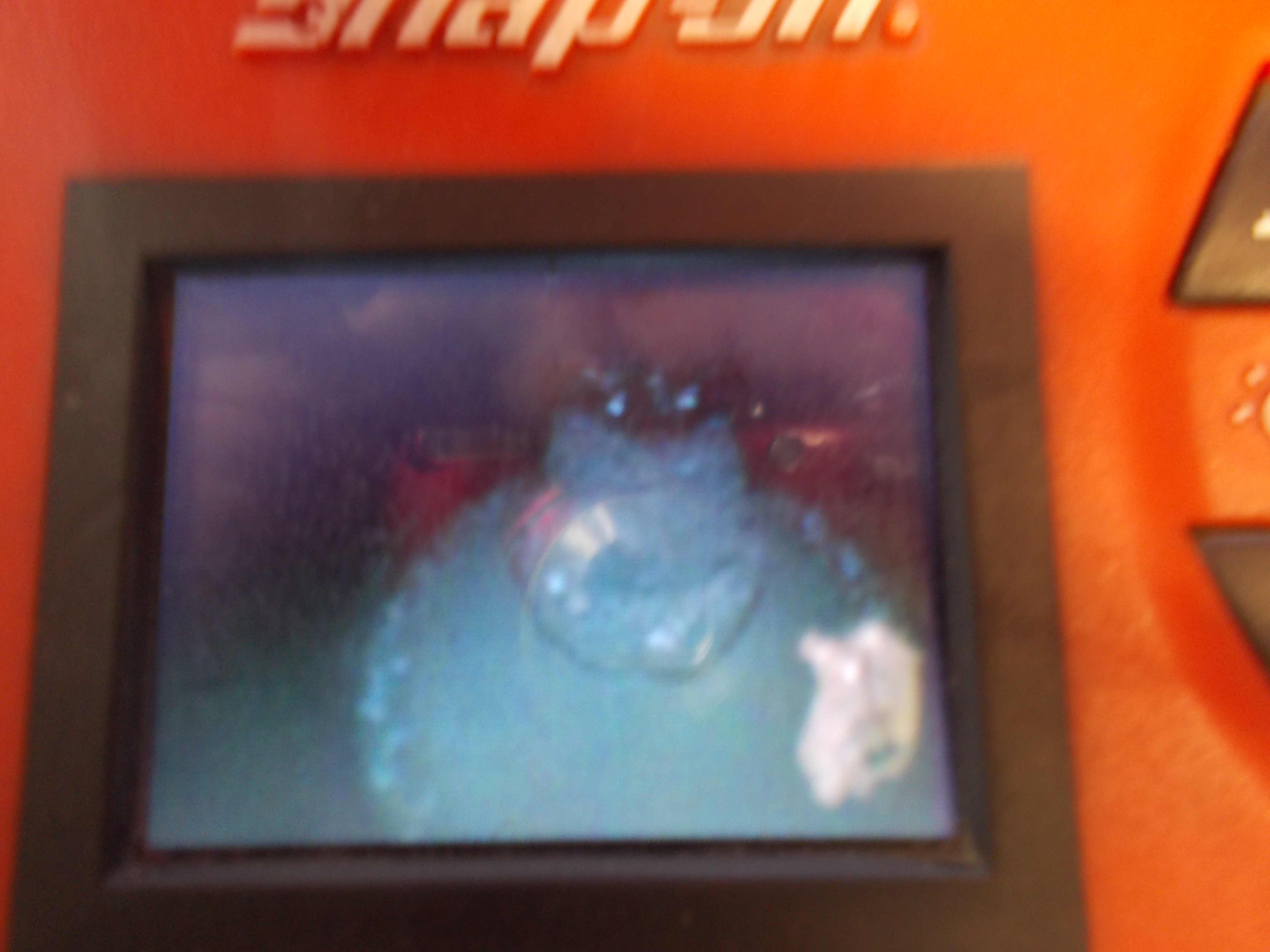
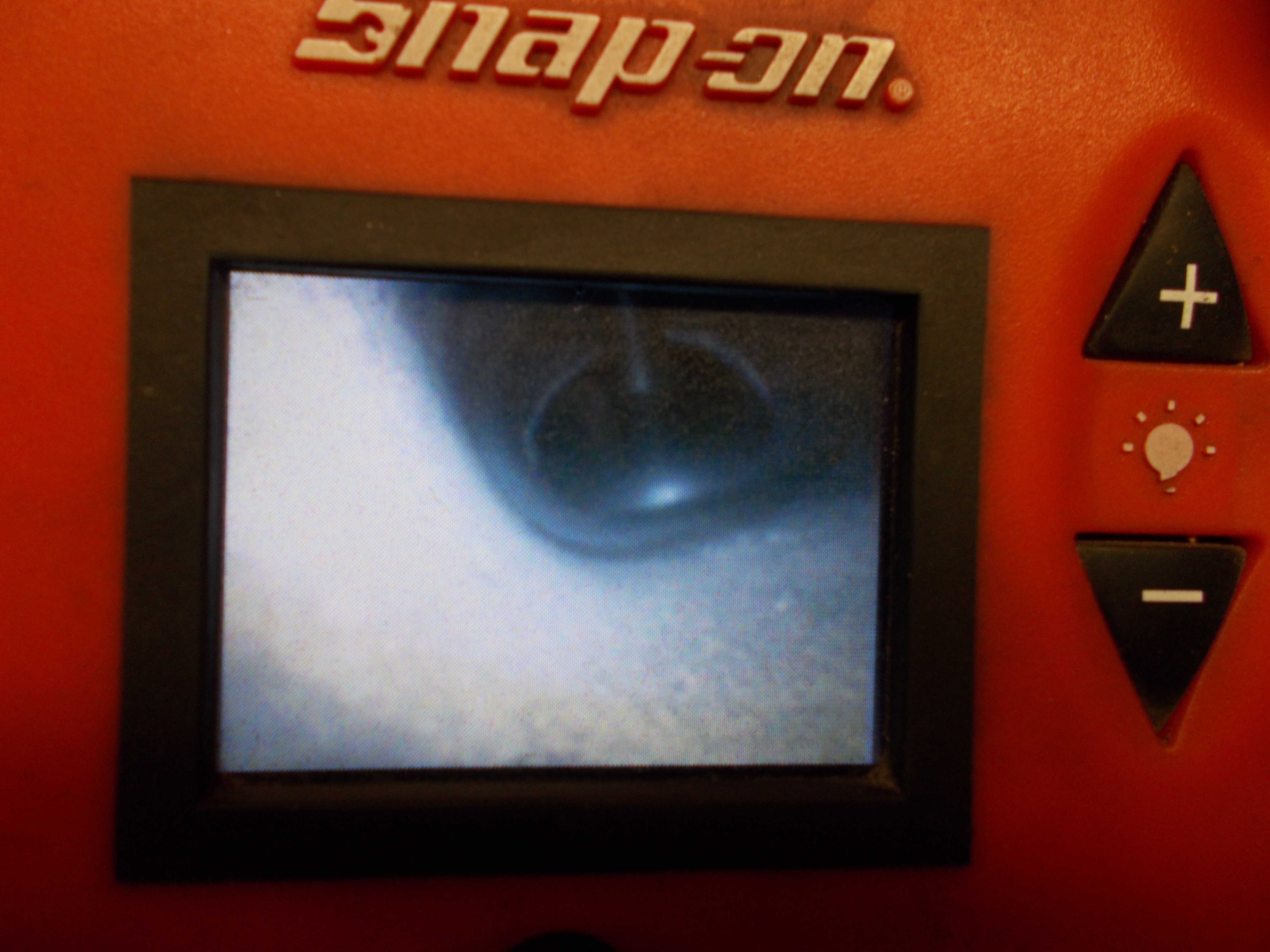
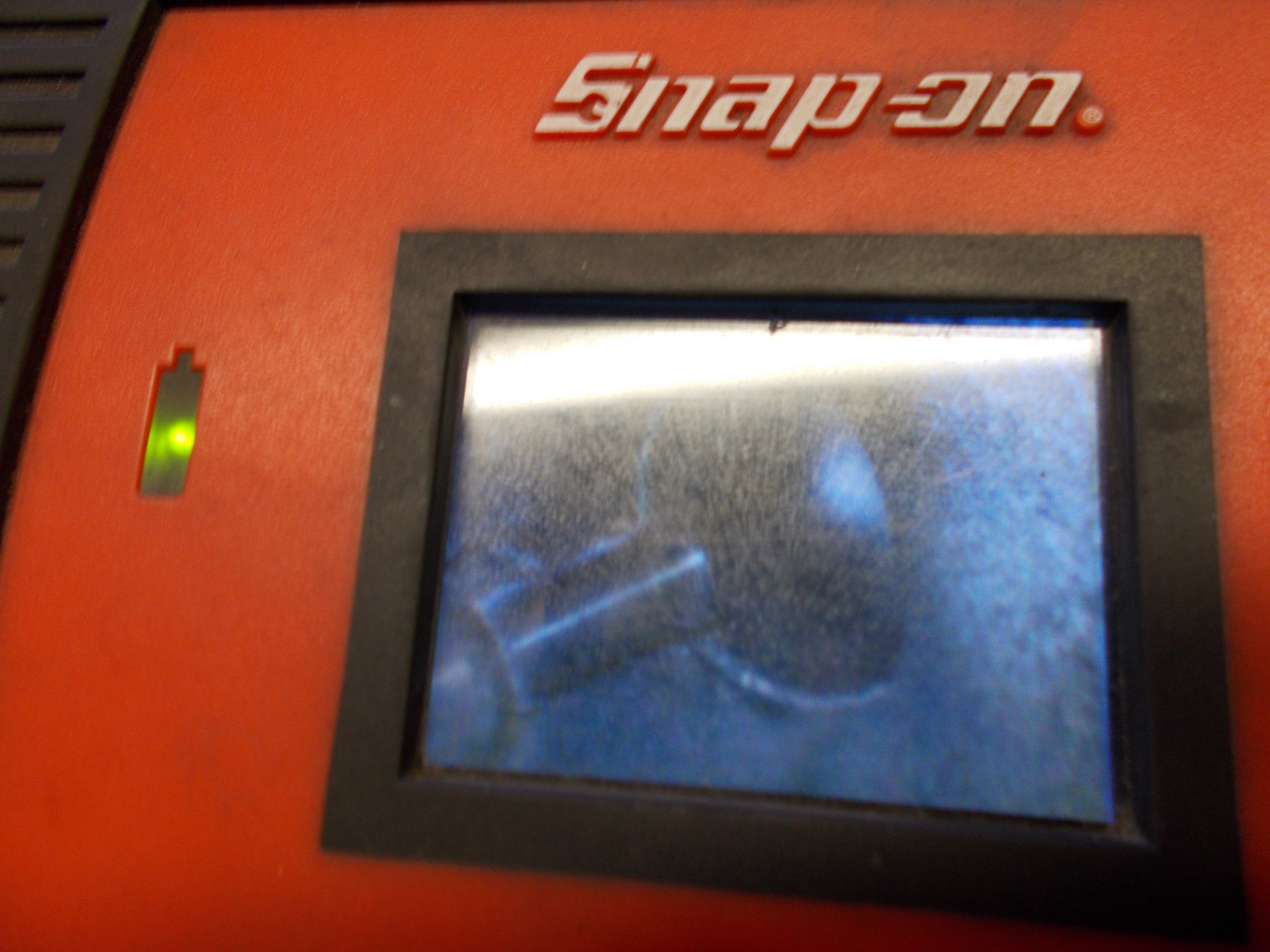
Here are valves through a boroscope (easy to do, or remove your own intake manifold and look at your own to see how severe the issue is):

And with the intake manifold removed:


Look inside most cans..look attractive from the outside but when examined, you see there is no way most can effectively separate and retain:
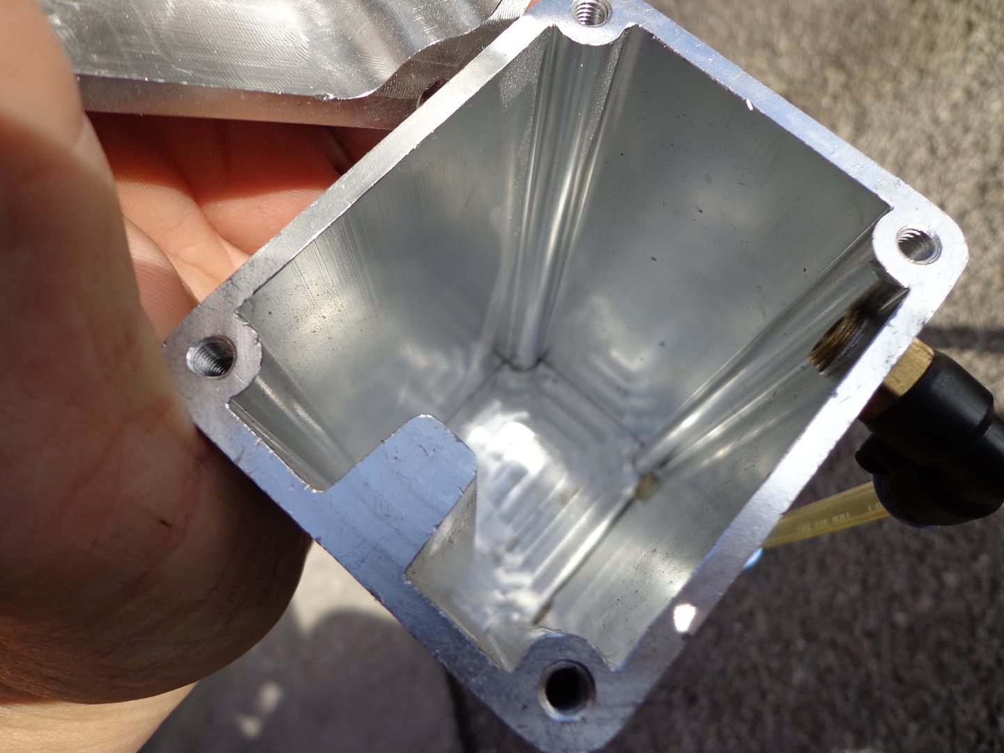
And another:
and more:
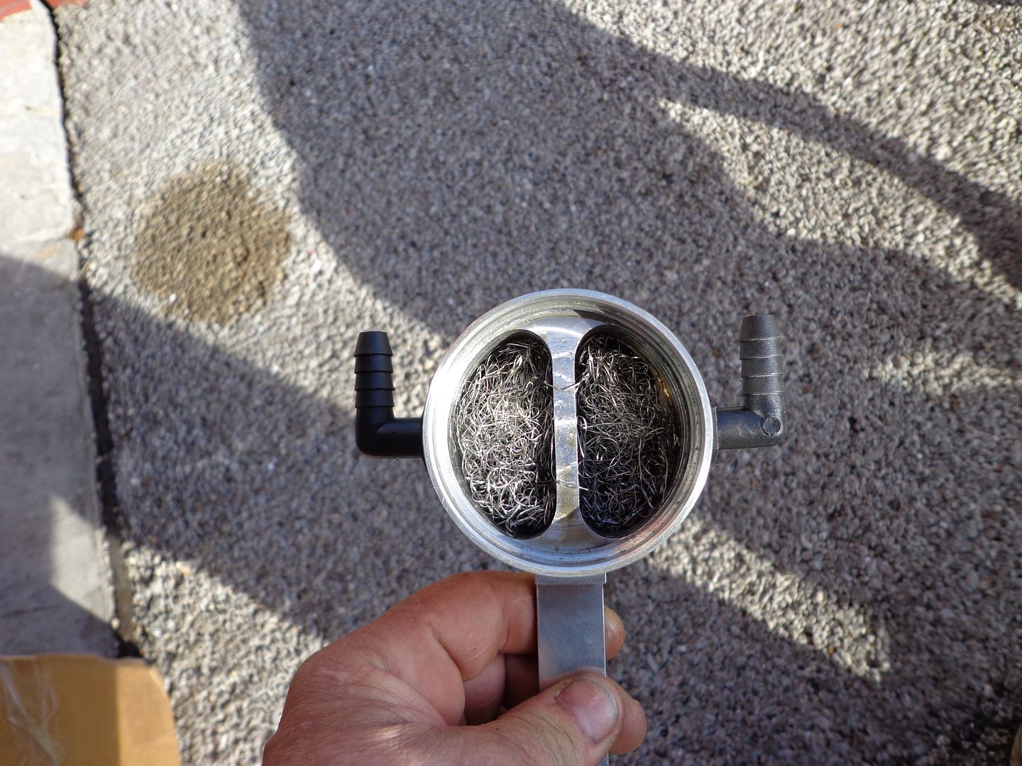
Look above, the inlet and outlet chambers are identical...both will saturate with oil in the media...fine with the inlet, but the outlet is like taking a wet washcloth and putting it to your move...now suck on it. You can't have a saturated media in the flow of the outlet without a good amount being sucked right out.
Being an Automotive Engineering and R&D firm, we have years of these we purchase, test, and cut apart to examine. Some screen, perforated material, etc. can only be partially effective. You must use several principals in a design that is effective. Coalescing, condensing, the Venturi effect, the Bernoulli effect, and gravity. Calculating the CFM of flow, and the speed, or velocity of that flow. Determine the distance from and contained liquid or any droplets that are falling from suspension and the outlet so that it isn't acting just like a soda straw and some spilled Cola on the table....put the straw near the puddle and suck...see how the liquid is pulled off the table and into the straw. Size of the main container. Any smaller than say 12 oz's and most PCV systems flow will overwhelm and "pull through" most of the liquid being caught. And more.
I can guarantee with the proper system the coking deposits are reduced to nearly nothing, and most owner have no idea what the level of degrade volumetric efficiency their engine is at with the build up. Do a Google search on BMW Direct injection intake valve coking and see the hundreds of images uploaded by BMW technicians all over the world on all the DI engines, FI or NA:
https://www.google.com/search?q=BMW+...A&ved=0CD4QsAQ
This effects EVERY DI engine in the world, but 99.9% of owners are not aware as the degradation in power and fuel economy is gradual. Just ask someone that had a manual intake valve cleaning (walnut shell blasting, etc.)
how surprised they were at the re-found power and fuel economy.
Anxious to. Just need a Mini owner near our facility to come in and we will make one.
The link to the BMW images are showing all models of BMW DI engines and more.
Then lets look at the reversion, or residual vapors you describe. Where does this oil come from? It is from the intake air charge contaminated first with the oil vapor due to using a ineffective separating can. If you use one of the few that DO catch and retain most all the oil, then only a small amount of fuel vapor will be present and that will not result with any coking deposits.
You can see a comparison of 2 brand new DI engines (3.6L GM) one with 70 k miles on and no can, vs 68k miles with the RX installed right from the dealer.....and 30% plus blockage with the no can, and almost no visible deposits with the other that was equipped.
Again, just look at how most cans are constructed, and you see it is impossible even with basic knowledge on flow principals to see they cannot be more than marginally effective.
Here are valves through a boroscope (easy to do, or remove your own intake manifold and look at your own to see how severe the issue is):
And with the intake manifold removed:
Look inside most cans..look attractive from the outside but when examined, you see there is no way most can effectively separate and retain:
And another:
and more:
Look above, the inlet and outlet chambers are identical...both will saturate with oil in the media...fine with the inlet, but the outlet is like taking a wet washcloth and putting it to your move...now suck on it. You can't have a saturated media in the flow of the outlet without a good amount being sucked right out.
Being an Automotive Engineering and R&D firm, we have years of these we purchase, test, and cut apart to examine. Some screen, perforated material, etc. can only be partially effective. You must use several principals in a design that is effective. Coalescing, condensing, the Venturi effect, the Bernoulli effect, and gravity. Calculating the CFM of flow, and the speed, or velocity of that flow. Determine the distance from and contained liquid or any droplets that are falling from suspension and the outlet so that it isn't acting just like a soda straw and some spilled Cola on the table....put the straw near the puddle and suck...see how the liquid is pulled off the table and into the straw. Size of the main container. Any smaller than say 12 oz's and most PCV systems flow will overwhelm and "pull through" most of the liquid being caught. And more.
I can guarantee with the proper system the coking deposits are reduced to nearly nothing, and most owner have no idea what the level of degrade volumetric efficiency their engine is at with the build up. Do a Google search on BMW Direct injection intake valve coking and see the hundreds of images uploaded by BMW technicians all over the world on all the DI engines, FI or NA:
https://www.google.com/search?q=BMW+...A&ved=0CD4QsAQ
This effects EVERY DI engine in the world, but 99.9% of owners are not aware as the degradation in power and fuel economy is gradual. Just ask someone that had a manual intake valve cleaning (walnut shell blasting, etc.)
how surprised they were at the re-found power and fuel economy.
Anxious to. Just need a Mini owner near our facility to come in and we will make one.
The link to the BMW images are showing all models of BMW DI engines and more.
All kind of interesting but again, the deposits come from a couple sources and a large contributor is oil down the intake guides especially under closed throttle decel. This oil loves to stick to the intake valves. Especially when one has some wear on them from high mileage cars.
I stated that I am venting to atmosphere so there can be no association between carbon build up from a poorly design oil catch can( not to be confused with a good oil separator) /crank case venting system and another source for carbonization.
I do have a question; why does one need to reintroduce air into the crank case? I've heard this and even seen it but why? Its not a sealed crank case like on Porsche engines. I do wonder how I can get vacuum to assist in pulling all the crank fumes out with causing a vacuum leak. Can I use the vacuum pump to do this?
2nd Gear
Joined: Jan 2015
Posts: 105
Likes: 3
From: Florida
All kind of interesting but again, the deposits come from a couple sources and a large contributor is oil down the intake guides especially under closed throttle decel. This oil loves to stick to the intake valves. Especially when one has some wear on them from high mileage cars.
I stated that I am venting to atmosphere so there can be no association between carbon build up from a poorly design oil catch can( not to be confused with a good oil separator) /crank case venting system and another source for carbonization.
I do have a question; why does one need to reintroduce air into the crank case? I've heard this and even seen it but why? Its not a sealed crank case like on Porsche engines. I do wonder how I can get vacuum to assist in pulling all the crank fumes out with causing a vacuum leak. Can I use the vacuum pump to do this?
Sorry for the late reply. Great post BTW.
You will always have a small amount of oil entering past the rings and that can cause slight coking, but most will never touch the valves to bake on.
The crankcase is always being bombarded with harmful combustion by-product compounds, and if these are not evacuated (removed) as soon as the y enter while still in a suspended state, they quickly settle and mix with the oil (as well as condense on the metal parts and cause corrosion). Just venting only relieves pressure and a small amount of these damaging compounds. Unless you are "flushing" them out with filtered, MAF metered fresh air enter one side of the crankcase, and foul oil and damaging compound laden vapors out the opposite, your shortening the engine life substantially. Of course this is gradual and takes time before it is obvious with bearing wear and added excess oil consumption, but it is happening just the same, and an oil analysis will show the elevated metal and acid content.
Think of it as a room.....windows on each end. Smoke is entering through a vent in the floor and fills the room. Open one window, and the pressure from the smoke entering will escape, and some of the smoke....but unless you open the opposite window, and add a fan for a better comparison, you will never clear the room.
Your assumption is very common, as crankcase pressure is the only real evident and obvious part of a proper PCV/Crankcase evacuation system, but it does far more as this training video shows (watch several times to gather all, but be aware it does not address forced induction...only naturally aspirated engines):
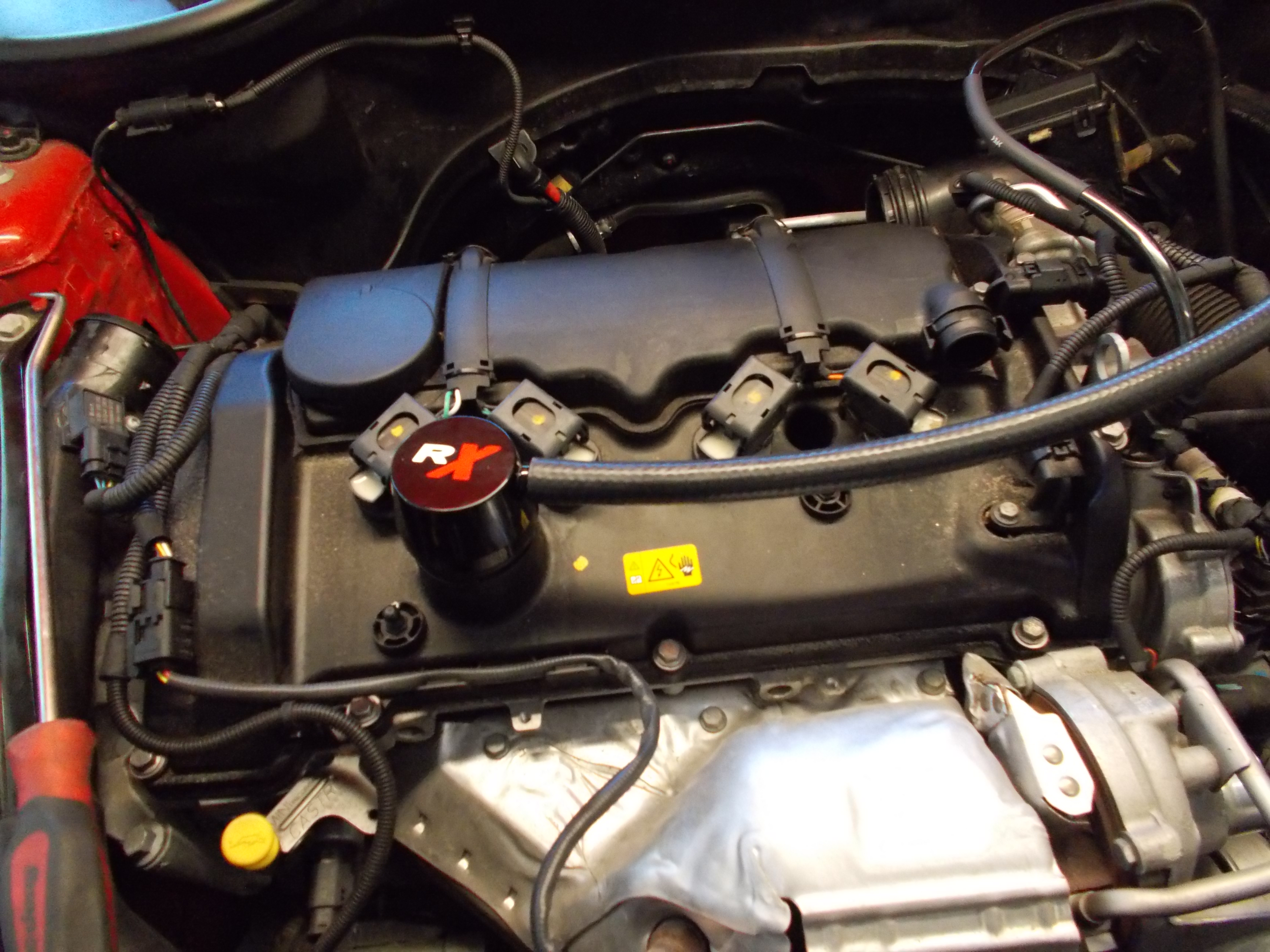
Also, we had a 2012 Mini S in this week, and at 30k miles we removed the intake manifold and examined the intake valves:
(Pretty horrible as this results in disrupted air flow and also uneven a/f mixture among the cylinders. First signs are generally rough idle and hesitation off idle acceleration as well as lower power and fuel economy. The valves are designed to result in a certain volumetric efficiency in the entire port/valve design. The fuel is delivered evenly to each cylinder and the ECU is expecting even air entering as well. Disrupt this and you are not burning at optimum efficiency.)

We then performed the crushed walnut shell media blasting method to clean them and we did a before, and after dyno runs to document the power gains from this cleaning:
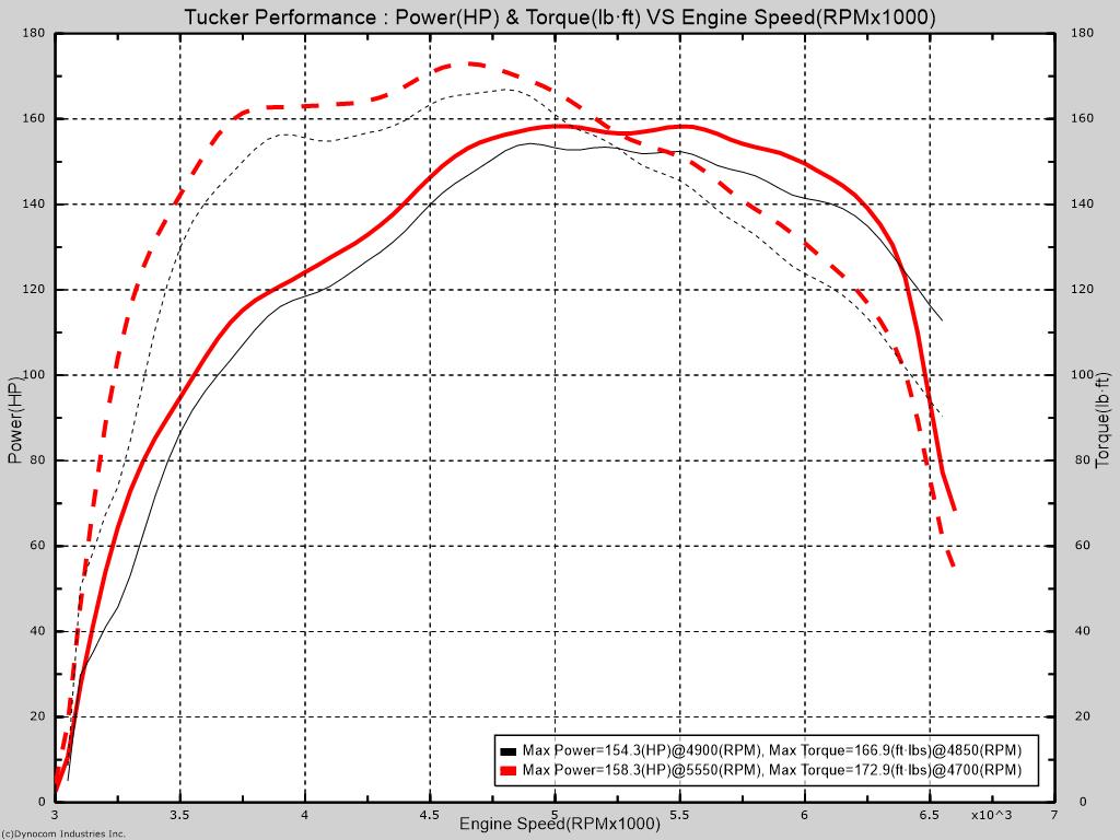
Note the power gains after the cleaning to see how dramatic the coking affects power, and of course fuel economy as well.
Peak gains are 4 whp and 6 wtq, but look at the more dramatic gains under peak RPM's. Right from the hit, there is as much as 8-12 wtq gains where it makes the most difference it acceleration.
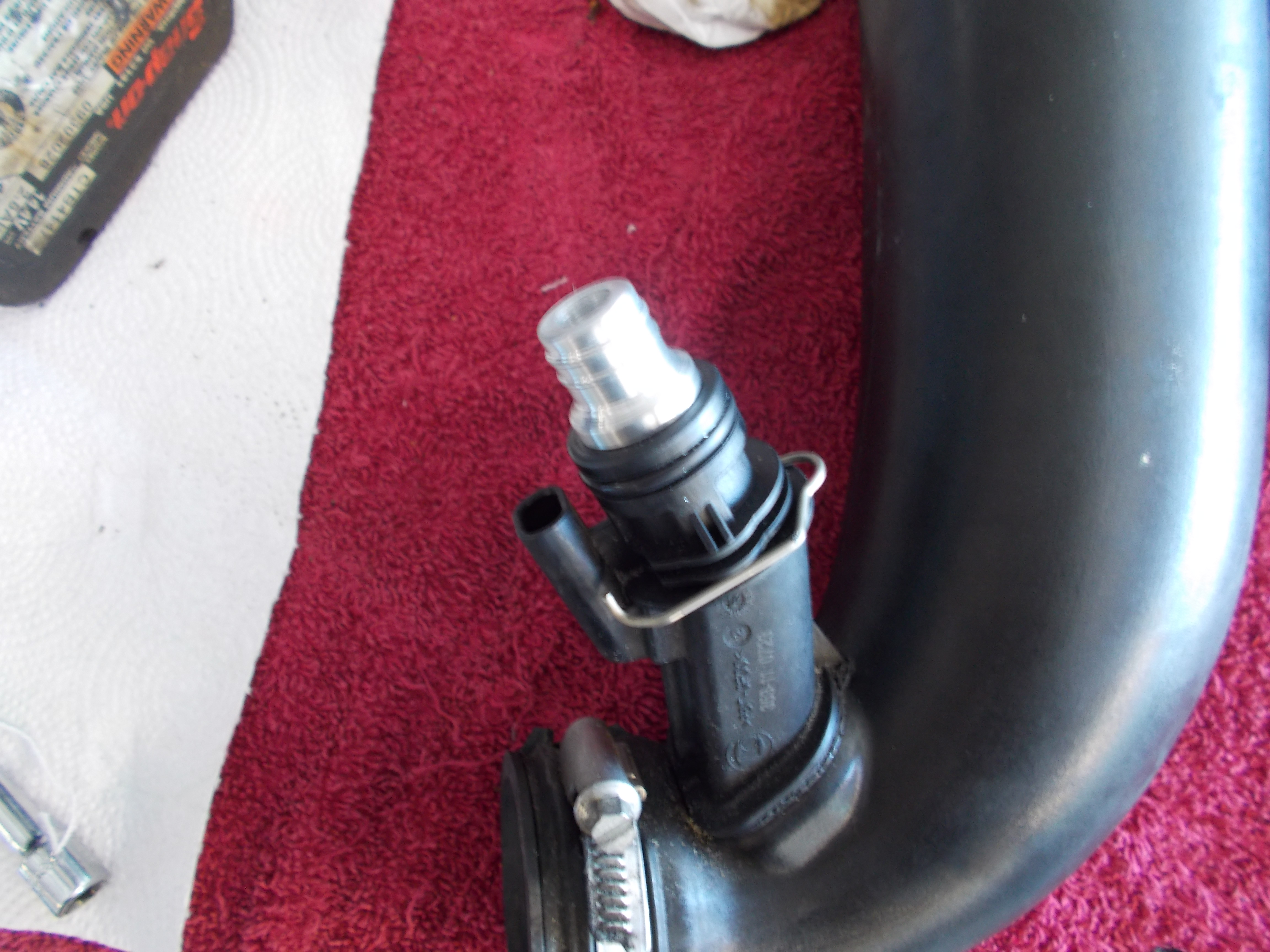
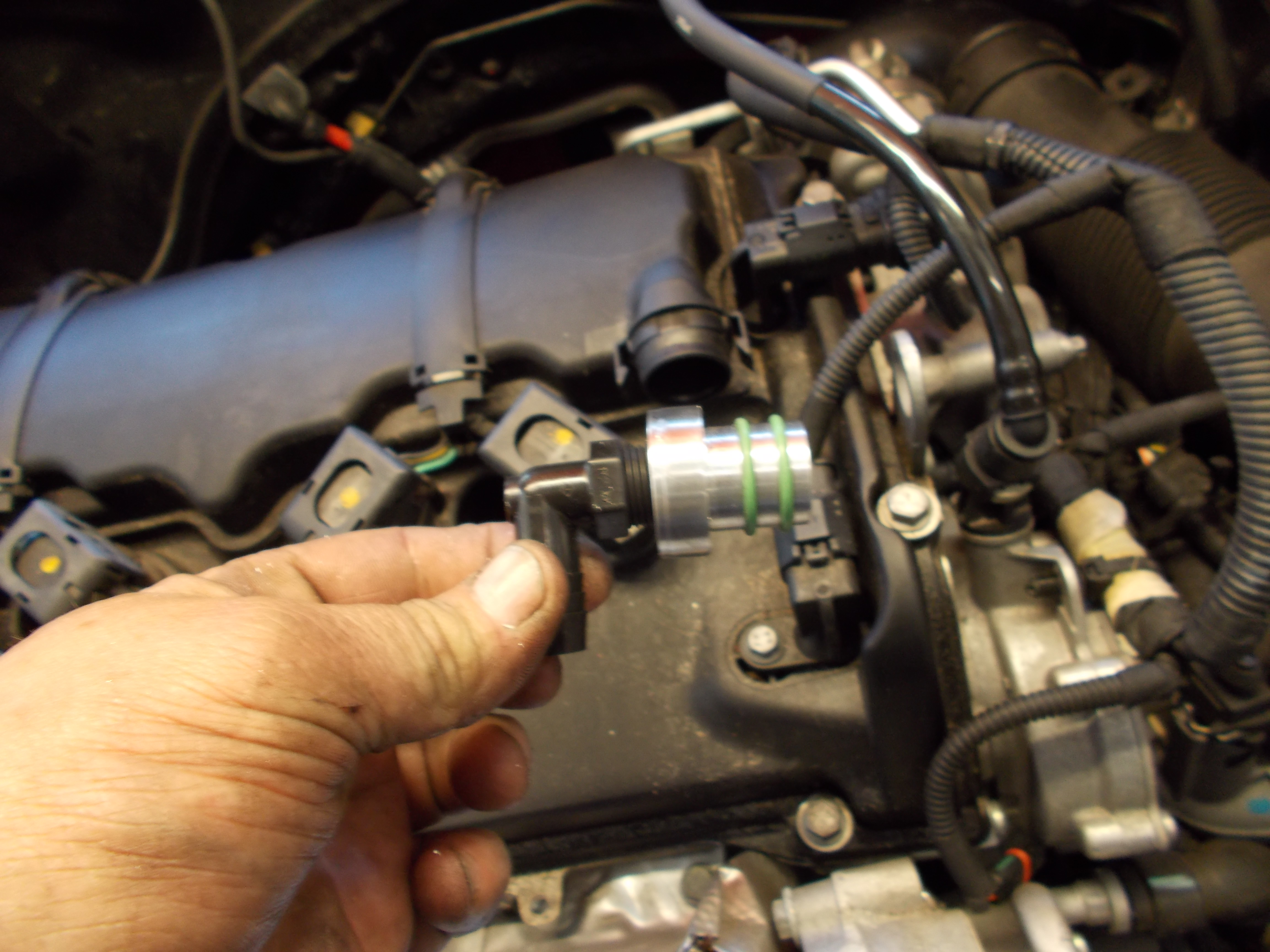
Here is the final solution:
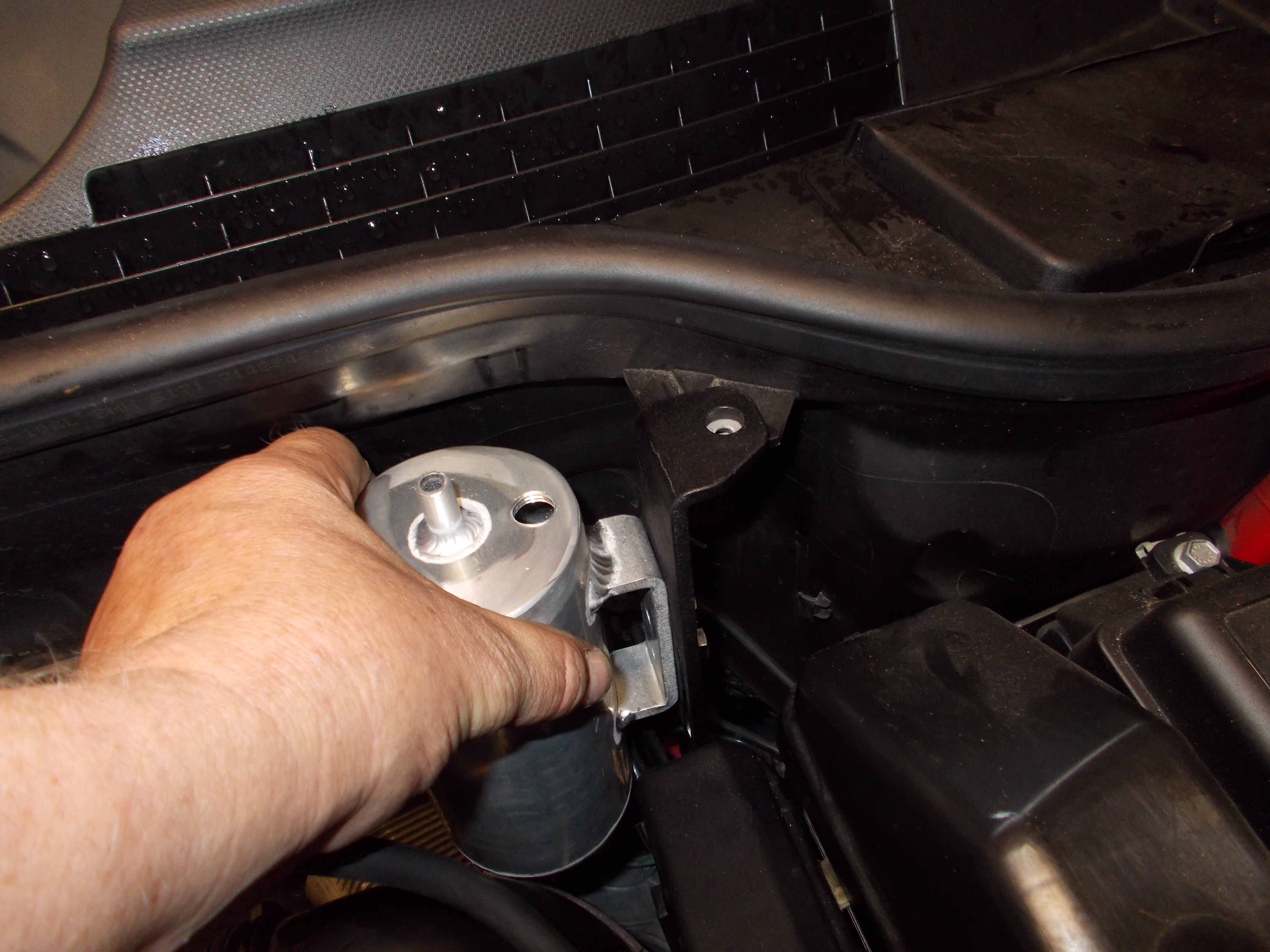
And we had to make several billet adaptors to make it "plug n play".
 .
.Will add to this as we get a 2007-2011 model in as they changed in 2012 slightly.
Another member here is sending us some parts as well and he will have a finished system.
The mount location of the separator for the foul/dirty side is very tight, and the can rubs on the air boxt so still working on that and more.
Keep the good questions coming. I will try to visit at least once a week to answer.

3rd Gear
Joined: Nov 2014
Posts: 241
Likes: 2
From: Seattle, WA
Love this thread.
Any one in New England want to take a look at their intake valves I'll help you out. I can do cleaning too... https://www.northamericanmotoring.co...ted-today.html
Any one in New England want to take a look at their intake valves I'll help you out. I can do cleaning too... https://www.northamericanmotoring.co...ted-today.html
2nd Gear
Joined: Jan 2015
Posts: 105
Likes: 3
From: Florida
indimanic, if the engine has over 20-30k miles on it, the valve guides are already worn from the deposits on the valve stems cycling into the guide, so oil WILL ingest from passing the valve seals and guides and will cause some coking. We are seeing excess valve guide tolerances at as low as 20k miles and that has something we haven't seen in the past 20-25 years with port injection. So that would be a path even with a deleted PCV system.