
Drivetrain My build thread.


5th Gear
Joined: Jul 2011
Posts: 1,025
Likes: 2
From: Los Angeles
Sounds like you should have got a S2K

Thread Starter
|
5th Gear
Joined: Apr 2011
Posts: 668
Likes: 4
Serious bad news. Cometic doesn't make a gasket for the R56. Even worse, I can't find anyone that does. So as of right now this build is dead till I can find a gasket or get one custom made. Any ideas?


6th Gear
Joined: May 2010
Posts: 3,260
Likes: 87
From: Pacific NW

4th Gear

Joined: May 2006
Posts: 426
Likes: 23
http://www.us.mahle.com/MAHLE_North_America/en/Home_EN
http://www.mahle-aftermarket.com/MAH...rvices/Gaskets
Robbo

Neutral
Joined: May 2008
Posts: 2
Likes: 0
From: Finland
Nice thread! Did you renew the valve seals? I'm trying to find Viton ones for my rebuild, but it's quite difficult to find aftermarket parts for R56 /EP6 engine.. I don't want to use originals. Does anyone know guide OD and height for the original seal? Could any of these fit? Valve OD is 5mm http://www.cometic.com/catalogs/sportcompact.pdf

There has to be someone who has done this. Czar, Thumper?
There is another way to look at it:
Does your piston come above deck? If not, then there will not be a mechanical interference between piston and head gasket.
Is your engine builder nervous if the head gasket is exposed by .26 mm (.010 inch) per side at the top of the chamber? Is the bore on the head gasket round (I'm a muscle car guy, and it is common to have non-round bores). Depending on the head gasket design, this may or may not create a hot spot area in the chamber.
Again, there has to be some MINI engine builders that can shed some light on things. Maybe Jan the tuner? I'm just reciting some of the names that I have read on the forum.
Good luck,
Mike
Thread Starter
|
5th Gear
Joined: Apr 2011
Posts: 668
Likes: 4
Got it all figured out. Victor Reinz forwarded my message to Mahle who messaged me today with the US equivalent part number. The only place able to order it, CarQuest. Who would of thought. Anyway it will be here tuesday.
Thread Starter
|
5th Gear
Joined: Apr 2011
Posts: 668
Likes: 4
So I got the measurements of my pistons today. They all measure 76.93 +/- .01 But the rings on the other hand were wore out. The combination of the added boost and the overheating did not do them kindly. The stock rods are in perfect shape the. They guys at the machine shop said they could barley see any signs of wear. As for info on the pistons they are cast and made by Mahle. Now I have a set of perfectly usable pistons and rods with no use for them. Any ideas on what to do with them?
Oh, I should add It took we hours to get them clean. The carbon buildup gets caked into the intake valve reliefs then gets cooked in place. Very hard to get off.
Oh, I should add It took we hours to get them clean. The carbon buildup gets caked into the intake valve reliefs then gets cooked in place. Very hard to get off.

Thread Starter
|
5th Gear
Joined: Apr 2011
Posts: 668
Likes: 4
Ok so got the head gasket and everything is on its way to being put back together.
Additionally here is my solution to the carbon buildup issue.
My solution to carbon buildup.
So after reading through all the posts about catch cans and our PVC system I decided this is the easiest thing to do.
First I contacted CZAR and purchased to of the caps from him.
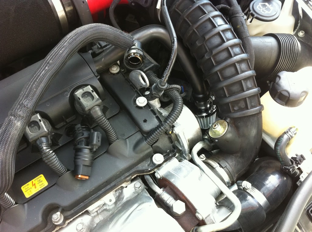
Then I removed to hose from the crankcase to the manifold and put in the two caps.
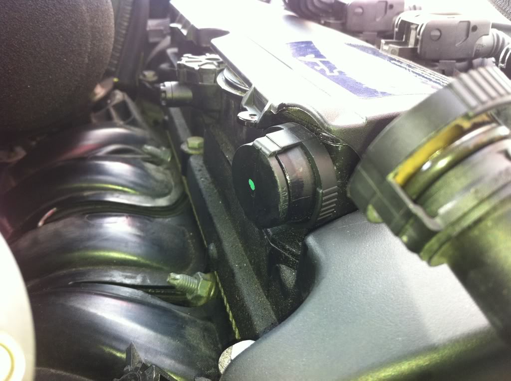
Then I went to the local auto parts store and picked up a neoprene plug and a breather filter (to substitute till I can get an appropriate length hose to run under the car)
This is the end result.
I have a longer hose now so all the crankcase gasses are come out of the front port and away into the air under the car. Not in my motor at all. If any of you are worried that this may cause positive pressure in your valve cover or crank case it wont. This is why,
So after all this talk about the PCV system I decided to go grab my valve cover and do a little investigating. Thanks to CZAR for cutting apart one of his valve covers and taking a bunch of pictures (which I tactfully acquired), I can give an even more detailed explanation of what is going on.
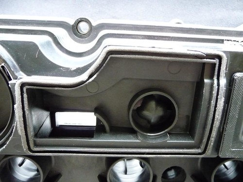
Ok so first we have the underside of the valve cover. As you can see in the picture below there are two ways for air to enter/exit the valve cover. The orange circle is a one way valve that will only let air into the valve cover. The white rectangle is an open port that will let air in or out. Mainly this is for air extraction. The white is just a paper towel I stuffed in the port so it would be more visible in the picture.
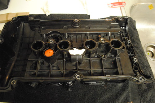
This is a picture of the extraction area of the PCV system
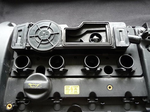
A view of the extraction port from the top side of the valve cover.
Open and closed flaps on the intake side of the PCV system.


Some pictures of this baffle thing.


Open and closed flaps on the manifold side of the PCV system.


Now that you have seen all the components, I will try to explain how this whole thing works. I sacrificed my lungs and braincells for this, so enjoy.
1. Either the rear or front PCV port can use vacuum to extract air from the valve cover. However neither port can force air into the valve cover.
2.When you block off one port the other is still able to extract air from the valve cover. The front port is more free flowing then the rear.
3.Blocking off the rear port will not cause pressure to build in the valve cover. The pressure will be able to escape from front port.
4.The orange one way valve is slightly confusing. It can only circulate air from the extraction port not air from outside. I think it is used as a way for oil to condense and drain back into the head. That way only fumes escape.
That pretty much sums it up. This should put all of the "PCV system" threads to rest. Questions? Ask away.
Additionally an explanation from CZAR
There you have it. No more carbon buildup.
Additionally here is my solution to the carbon buildup issue.
My solution to carbon buildup.
So after reading through all the posts about catch cans and our PVC system I decided this is the easiest thing to do.
First I contacted CZAR and purchased to of the caps from him.
Then I removed to hose from the crankcase to the manifold and put in the two caps.
Then I went to the local auto parts store and picked up a neoprene plug and a breather filter (to substitute till I can get an appropriate length hose to run under the car)
This is the end result.
I have a longer hose now so all the crankcase gasses are come out of the front port and away into the air under the car. Not in my motor at all. If any of you are worried that this may cause positive pressure in your valve cover or crank case it wont. This is why,
So after all this talk about the PCV system I decided to go grab my valve cover and do a little investigating. Thanks to CZAR for cutting apart one of his valve covers and taking a bunch of pictures (which I tactfully acquired), I can give an even more detailed explanation of what is going on.
Ok so first we have the underside of the valve cover. As you can see in the picture below there are two ways for air to enter/exit the valve cover. The orange circle is a one way valve that will only let air into the valve cover. The white rectangle is an open port that will let air in or out. Mainly this is for air extraction. The white is just a paper towel I stuffed in the port so it would be more visible in the picture.
This is a picture of the extraction area of the PCV system
A view of the extraction port from the top side of the valve cover.
Open and closed flaps on the intake side of the PCV system.
Some pictures of this baffle thing.
Open and closed flaps on the manifold side of the PCV system.
Now that you have seen all the components, I will try to explain how this whole thing works. I sacrificed my lungs and braincells for this, so enjoy.
1. Either the rear or front PCV port can use vacuum to extract air from the valve cover. However neither port can force air into the valve cover.
2.When you block off one port the other is still able to extract air from the valve cover. The front port is more free flowing then the rear.
3.Blocking off the rear port will not cause pressure to build in the valve cover. The pressure will be able to escape from front port.
4.The orange one way valve is slightly confusing. It can only circulate air from the extraction port not air from outside. I think it is used as a way for oil to condense and drain back into the head. That way only fumes escape.
That pretty much sums it up. This should put all of the "PCV system" threads to rest. Questions? Ask away.
Additionally an explanation from CZAR
Firstly let me explain a little about the PCV, PCV is an acronym for Positive crankcase ventilation, inside the cam cover there are a few entrapment passages and direction chambers, which do their best to separate the suspended oil particles from the passing vapour, this vapour is then vacuum drawn from the cam cover passageways through a valve flap, the first direction is through the rear PCV line into the intake manifold, next, when the vacuum draw from the turbo (building boost pressure) is greater than the vacuum draw of the induction stroke from the pistons, the rear PCV valve flap is closed, as is the diaphragm in the cam cover, this then changes the direction flow of the vapour, and the vapour is vacuum drawn through the passenger side PCV valve flap into the air intake flow pre-turbo, once off boost and steady throttle is resumed then the vapour is once again vacuum drawn through the rear PCV line.
Now the actual valve flaps themselves are merely free falling self closing rubber diaphragms, there is no spring or piston actuation on either valve flap, however there is a sprung chamber diaphragm, which opens/closes under the vacuum draw from both the inlet manifold and turbo vacuum draw, this dictates the flow direction, and in the later re-designed cam cover allows excess pressure to vent through the inbuilt pressure release sprung valve.
Now the actual valve flaps themselves are merely free falling self closing rubber diaphragms, there is no spring or piston actuation on either valve flap, however there is a sprung chamber diaphragm, which opens/closes under the vacuum draw from both the inlet manifold and turbo vacuum draw, this dictates the flow direction, and in the later re-designed cam cover allows excess pressure to vent through the inbuilt pressure release sprung valve.
There you have it. No more carbon buildup.

1st Gear
Joined: Nov 2012
Posts: 47
Likes: 1
From: Milwaukee, WI
MNIPWR, I salute you. I only recently got into the MINI world, coming from a Yaris with a 1NZFE. In the two-ish years I owned that car, I learned a lot and was confident in what I wanted to do. Switching to the MINI, I was overwhelmed with how different it was. Thanks to you, and spending 20-30 minutes reading this entire thread, I know have more knowledge and understanding of the MINI engine than I did in the last two months of research.
Thank you SO much for documenting and explaining all of this so thoroughly, it's greatly appreciated, and I wish you the best of luck in your build. I'll be following (read: lurking) closely to see how this comes out.
Thank you SO much for documenting and explaining all of this so thoroughly, it's greatly appreciated, and I wish you the best of luck in your build. I'll be following (read: lurking) closely to see how this comes out.