
Navigation & Audio 100 Hz Rear Speaker Cutoff Cure!!


Thread Starter
|
3rd Gear
Joined: Jun 2007
Posts: 257
Likes: 4
From: Plano, TX
100 Hz Rear Speaker Cutoff Cure!!
So after running some numbers, poking around, and testing, I think I might have the solution to this 100 Hz cutoff crap.
But first, why am I ripping apart my dashboard, taking apart my stereo (and speedometer), messing around trying to find filters and just plain wasting my time?? Well, I'm a very picky listener. The problem with the MINI's cutoff is that you lose EVERYTHING between 100 Hz and ~25 (0 for short, even though we really can't hear that much). Now, I really detest Rap and R&B with a passion, so why would I care?? It just so happens that the music I listen to is modern rock, with it's crash-y high's and it's thumping lows. And to make matters worse, I play the drums which means.... you guessed it, I LIKE my drum hits!! Another problem is that the electric guitar's fundamental frequency is around 50ish Hz... which means that because of this stupid filter, you lose the fundamental AND the 1st harmonic!!! WTF!?!?!
Needless to say that a good deal of instruments sit around those frequencies... and well, you can't just take your fronts and switch them with your rears because... you sit in the front!! Sure the fronts (when replaced with speakers that are worth more than $5.00) don't necessarily need the sub-sonic frequencies... but they do a good job of reproducing a wide range of them... and if you equalize properly, I promise you that they'll use every single range you throw at them!!
Now enough ranting, time for some math!!
Well, first off, here's an updated picture of the schematic:
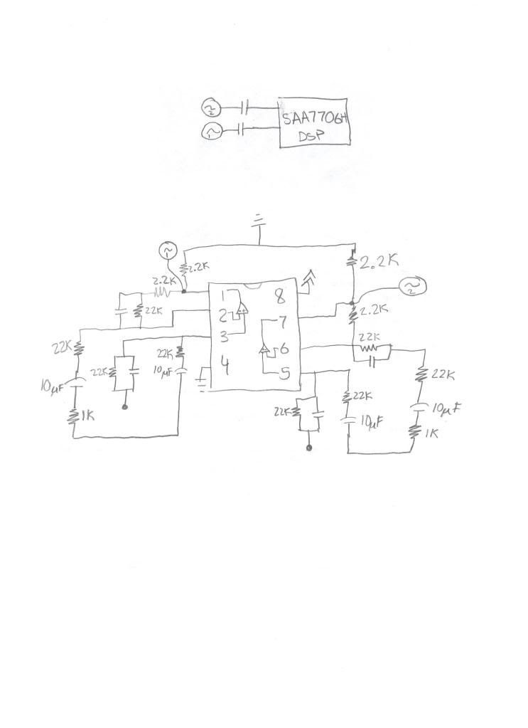
In this picture we see that there are a couple RC filters set up between the op-amps as well as a series RC filter on the output. Well, if you look in my EE textbook (or on this page, for those of you who like webpages) you'll find some active filter examples. If you scroll down to the example titled "Simple Band Pass Filter with Op Amp" you'll find something that looks VERY similar to what we have in the schematic above... So it seems that we have a band pass filter!!! Hey!!
Alright, now let's do the small parallel RC circuits first. If we plug in some numbers into our handy google search, we find that the high pass cutoff frequency is...... 1 / (22 000 * 100e-12) = 454 545.455 Hz or, 455 KHz... completely out of range for audio... great. Thanks MINI, you bunch of idiots.
Next, and here's the interesting part, let's run those numbers for the series RC. 1/(1000*10e-6) = 100 Hz... well I'll be a monkey's uncle... MINI you bunch of fumbling bafoons!!! What the hell were you all thinking?!?!?!
Anyway, long story short, MINI's engineers decided to run this amplifier without any gain whatsoever (unity gain, a.k.a buffer amplifier) and just use it for filtering. In theory, we could just pull our signals out before the filter, but why do that!? Let's mod the circuit so it works just fine (and MINI mechanics have no effing clue that you messed with anything).
All you have to do is remove these 4 capacitors shown in the schematic, bridge the pads with solder or a small wire, and voala, you're done!!! No more filter!!!
You will have a nice smooth-ish response!!!
Now, I have yet to test the removing of the 10 uF capacitors, but I can safely say that removing the 100 pF capacitors doesn't really do anything (that I can hear). I'm sure that MINI wanted that to be a bandpass filter to remove some HF noise somewhere, but I can't hear it... and if I do, I'll just put the caps back on, no biggie. My speakers can't even reproduce that anyway.
Now there is no warranty of any kind (explicit or implied) that this won't kill your stereo, your car's computer, your dog, your goldfish or anything else worth killing, but it all makes sense. There's math behind it and if you followed me this far and know how to solder, you know what you're getting into.
I'll add some more pictures, a more detailed writeup, a tutorial, and all that goodness tomorrow. It's time for beer.
UPDATED-UPDATED-UPDATED-UPDATED
Alright guys, so I did some more digging, tracing, IC hunting, etc and found out some more info.
It seems that the op-amp that I found is indeed a band pass filter, and removing it did help a bit, BUT there's a slight hitch. I traced the remaining traces until I found out exactly what everything was connected to. It turns out that the pin locations I have marked as inputs are actually outputs and vice-versa. What's happening is that the op-amp's input is actually connected to the AUX Left and AUX right inputs, meaning that if you were to connect an ipod to the AUX input of the MINI, anything under 100 Hz would be removed. If we take a look at k6rtm's work over on this post, we can see that all tests were run under the assumption that the AUX line had a completely linear response.
What does this mean? This tells us two things. First, the results from the previously mentioned post are most likely wrong (but beautifully executed, I hope to follow those same procedures once it gets a bit warmer, possibly tomorrow). Second, that filter that I found isn't what we were looking for.
This all makes us think of this question: "How the hell is our 100 Hz getting cut off??"
Well, my theory is as follows:
I've been looking at this board for over 8+ hours now. From what I can infer about the circuit topology, the heart of the system is the SAA7706H DSP. This chip is in charge of all ADC and DAC conversions. It handles all inputs and outputs (AM, FM, AUX, Phone, Satellite, CD, etc.) and converts them into digital. This chip also, in turn, spits out the analog signals which are directly connected to the power amplifier. No fancy filters, nothing, nada, zip, zero. There's a direct short between the output pins of the chip and the input pins of the amplifier. After the amplifier, there's a direct short to the break-out board, and output connectors. This tells us that the filtering is, in fact, digital and there's nothing we can do about it!! Short of threatening a MINI engineer such that he gives us the code for the DSP or intercepting the I2C commands, there's not much we can do. I'll keep looking into the circuit some more, but I think it's very sound logic. If anyone has anything to add to the discussion after I post my findings, please, speak up!!
Now, why MINI engineers decided to filter the input before the DSP is beyond me. Maybe to simplify the ADC conversion? Maybe to allow for a smaller sampling rate? Maybe to provide isolation/impedance matching? Who knows. Fact is, that active filter is for the AUX in, not for the line out.
Will I keep the capacitors removed? You bet I will. Will it help at all? I don't think so. In my testing, I noticed slight improvements in lower frequency response (50 Hz wasn't completely dead, but it was definitely attenuated). It may be interesting to run the same tests k6rtm ran on his MINI to see what's going on or to see if there were any improvements. I did notice quite a bit more bass response using the function generator coming from my fronts, but no improvement from the rears :(
I'll keep poking around. I hope this has satisfied some of you more tech-savvy MINI enthusiasts, and I'm sorry I couldn't solve the problem completely
P.S. Mods, I'd totally love it if you'd sticky this post... It might keep people from asking "why the hell does my bass not sound good!?!?!"
But first, why am I ripping apart my dashboard, taking apart my stereo (and speedometer), messing around trying to find filters and just plain wasting my time?? Well, I'm a very picky listener. The problem with the MINI's cutoff is that you lose EVERYTHING between 100 Hz and ~25 (0 for short, even though we really can't hear that much). Now, I really detest Rap and R&B with a passion, so why would I care?? It just so happens that the music I listen to is modern rock, with it's crash-y high's and it's thumping lows. And to make matters worse, I play the drums which means.... you guessed it, I LIKE my drum hits!! Another problem is that the electric guitar's fundamental frequency is around 50ish Hz... which means that because of this stupid filter, you lose the fundamental AND the 1st harmonic!!! WTF!?!?!
Needless to say that a good deal of instruments sit around those frequencies... and well, you can't just take your fronts and switch them with your rears because... you sit in the front!! Sure the fronts (when replaced with speakers that are worth more than $5.00) don't necessarily need the sub-sonic frequencies... but they do a good job of reproducing a wide range of them... and if you equalize properly, I promise you that they'll use every single range you throw at them!!
Now enough ranting, time for some math!!
Well, first off, here's an updated picture of the schematic:
In this picture we see that there are a couple RC filters set up between the op-amps as well as a series RC filter on the output. Well, if you look in my EE textbook (or on this page, for those of you who like webpages) you'll find some active filter examples. If you scroll down to the example titled "Simple Band Pass Filter with Op Amp" you'll find something that looks VERY similar to what we have in the schematic above... So it seems that we have a band pass filter!!! Hey!!
Alright, now let's do the small parallel RC circuits first. If we plug in some numbers into our handy google search, we find that the high pass cutoff frequency is...... 1 / (22 000 * 100e-12) = 454 545.455 Hz or, 455 KHz... completely out of range for audio... great. Thanks MINI, you bunch of idiots.
Next, and here's the interesting part, let's run those numbers for the series RC. 1/(1000*10e-6) = 100 Hz... well I'll be a monkey's uncle... MINI you bunch of fumbling bafoons!!! What the hell were you all thinking?!?!?!
Anyway, long story short, MINI's engineers decided to run this amplifier without any gain whatsoever (unity gain, a.k.a buffer amplifier) and just use it for filtering. In theory, we could just pull our signals out before the filter, but why do that!? Let's mod the circuit so it works just fine (and MINI mechanics have no effing clue that you messed with anything).
All you have to do is remove these 4 capacitors shown in the schematic, bridge the pads with solder or a small wire, and voala, you're done!!! No more filter!!!
You will have a nice smooth-ish response!!!
Now, I have yet to test the removing of the 10 uF capacitors, but I can safely say that removing the 100 pF capacitors doesn't really do anything (that I can hear). I'm sure that MINI wanted that to be a bandpass filter to remove some HF noise somewhere, but I can't hear it... and if I do, I'll just put the caps back on, no biggie. My speakers can't even reproduce that anyway.
Now there is no warranty of any kind (explicit or implied) that this won't kill your stereo, your car's computer, your dog, your goldfish or anything else worth killing, but it all makes sense. There's math behind it and if you followed me this far and know how to solder, you know what you're getting into.
I'll add some more pictures, a more detailed writeup, a tutorial, and all that goodness tomorrow. It's time for beer.
UPDATED-UPDATED-UPDATED-UPDATED
Alright guys, so I did some more digging, tracing, IC hunting, etc and found out some more info.
It seems that the op-amp that I found is indeed a band pass filter, and removing it did help a bit, BUT there's a slight hitch. I traced the remaining traces until I found out exactly what everything was connected to. It turns out that the pin locations I have marked as inputs are actually outputs and vice-versa. What's happening is that the op-amp's input is actually connected to the AUX Left and AUX right inputs, meaning that if you were to connect an ipod to the AUX input of the MINI, anything under 100 Hz would be removed. If we take a look at k6rtm's work over on this post, we can see that all tests were run under the assumption that the AUX line had a completely linear response.
What does this mean? This tells us two things. First, the results from the previously mentioned post are most likely wrong (but beautifully executed, I hope to follow those same procedures once it gets a bit warmer, possibly tomorrow). Second, that filter that I found isn't what we were looking for.
This all makes us think of this question: "How the hell is our 100 Hz getting cut off??"
Well, my theory is as follows:
I've been looking at this board for over 8+ hours now. From what I can infer about the circuit topology, the heart of the system is the SAA7706H DSP. This chip is in charge of all ADC and DAC conversions. It handles all inputs and outputs (AM, FM, AUX, Phone, Satellite, CD, etc.) and converts them into digital. This chip also, in turn, spits out the analog signals which are directly connected to the power amplifier. No fancy filters, nothing, nada, zip, zero. There's a direct short between the output pins of the chip and the input pins of the amplifier. After the amplifier, there's a direct short to the break-out board, and output connectors. This tells us that the filtering is, in fact, digital and there's nothing we can do about it!! Short of threatening a MINI engineer such that he gives us the code for the DSP or intercepting the I2C commands, there's not much we can do. I'll keep looking into the circuit some more, but I think it's very sound logic. If anyone has anything to add to the discussion after I post my findings, please, speak up!!
Now, why MINI engineers decided to filter the input before the DSP is beyond me. Maybe to simplify the ADC conversion? Maybe to allow for a smaller sampling rate? Maybe to provide isolation/impedance matching? Who knows. Fact is, that active filter is for the AUX in, not for the line out.
Will I keep the capacitors removed? You bet I will. Will it help at all? I don't think so. In my testing, I noticed slight improvements in lower frequency response (50 Hz wasn't completely dead, but it was definitely attenuated). It may be interesting to run the same tests k6rtm ran on his MINI to see what's going on or to see if there were any improvements. I did notice quite a bit more bass response using the function generator coming from my fronts, but no improvement from the rears :(
I'll keep poking around. I hope this has satisfied some of you more tech-savvy MINI enthusiasts, and I'm sorry I couldn't solve the problem completely
P.S. Mods, I'd totally love it if you'd sticky this post... It might keep people from asking "why the hell does my bass not sound good!?!?!"
Last edited by juchong; Dec 10, 2009 at 10:17 PM. Reason: Added more info.


6th Gear
Joined: May 2002
Posts: 3,433
Likes: 1
From: Gloucester, MA, USA
The (very) high pass filter might be targetting digital noise injected in to the analog stream - not filtering this could in theory stress the later amplification stages as they attempt to amplify the very high frequency noise.
For that reason, and since you can't hear it anyway, you'd be best to leave the high pass untouched.
For that reason, and since you can't hear it anyway, you'd be best to leave the high pass untouched.
Thread Starter
|
3rd Gear
Joined: Jun 2007
Posts: 257
Likes: 4
From: Plano, TX
The (very) high pass filter might be targetting digital noise injected in to the analog stream - not filtering this could in theory stress the later amplification stages as they attempt to amplify the very high frequency noise.
For that reason, and since you can't hear it anyway, you'd be best to leave the high pass untouched.
For that reason, and since you can't hear it anyway, you'd be best to leave the high pass untouched.
She came with standard audio, this is the regular Boost system.
Trending Topics


I've been looking at this board for over 8+ hours now. From what I can infer about the circuit topology, the heart of the system is the SAA7706H DSP. This chip is in charge of all ADC and DAC conversions. It handles all inputs and outputs (AM, FM, AUX, Phone, Satellite, CD, etc.) and converts them into digital. This chip also, in turn, spits out the analog signals which are directly connected to the power amplifier. No fancy filters, nothing, nada, zip, zero. There's a direct short between the output pins of the chip and the input pins of the amplifier. After the amplifier, there's a direct short to the break-out board, and output connectors. This tells us that the filtering is, in fact, digital and there's nothing we can do about it!! Short of threatening a MINI engineer such that he gives us the code for the DSP or intercepting the I2C commands, there's not much we can do. I'll keep looking into the circuit some more, but I think it's very sound logic. If anyone has anything to add to the discussion after I post my findings, please, speak up!!
Now just to state a few facts before I continue.
Both the Standard and HiFi use the same head unit. This has been proven more than once from numerous posts.
The Standard system has a 100 HZ roll off for the rear channels. Proven more than once from numerous posts.
The HiFi system does NOT have this roll off. Proven more than once from numerous posts.
MINI can program the head unit do do things the way it wants to. MINI can also program the HiFi Amplifier for different frequency responses and outputs. They have done this in my car, and it actually did sound a little better after they did so, but still very poor sounding to my ears. BTW the head unit also handles many other functions in the car as well.
Now with the facts stated. It is rather obvious and I have stated that MINI could PROGRAM this out if they wanted to. I have stated that a few times here on the forums. I.E. it is "Not" just a filter (capacitors/inductors etc) that was added to the circuity.
But great work anyway and thanks for the confirmation. I am not willing to take apart a warranty item until the warranty is over (another 18k mile for me).
Thread Starter
|
3rd Gear
Joined: Jun 2007
Posts: 257
Likes: 4
From: Plano, TX
There is just one more test I'm going to run in a couple minutes. I'm going to put a scope on the outputs coming directly from the DSP. If the levels are different, then it's digital filtering. If the outputs are the same, then there's still hope.

6th Gear
Joined: Mar 2007
Posts: 7,578
Likes: 5
From: Paradise
The HiFi system does NOT have this roll off. Proven more than once from numerous posts.
My theory is that they had trouble with rear panels buzzing from low freq. coming through the 6x9 speakers. Rather than redesign the rear panels, they took the easy way out and cut bass to the rear. Perhaps the problem was discovered after the rear panels were finalized and injection molds made.
Yes correct. I should have stated it better.

4th Gear
Joined: Feb 2008
Posts: 447
Likes: 1
From: Silicon Valley
I'm confused...
I'm confused.
I agree with the analysis that points to that big, fat, DSP.
And I agree the circuitry sketched out is a simple filter, with component values for a corner around 100Hz at the low end.
Now here's where I get confused -- I connect my signal generator (HP 3314A) to the aux inputs. The sig gen has a leveled output -- it's flat, within a fraction of a dB, from one end to another (verified with my low-end analogue scope as well, a Tek SC504, flat to 80MHz).
If the hypothesis is that the opamp hi-pass filters are between the Aux input and the rest of the circuitry, then how do we see the response I measured (and plotted) for the front channel speakers, where the amplitude goes up below 100 Hz, leveling off around 40Hz or so, and the rears drop off? If the high-pass filters were situated as I read things, wouldn't they drop both front and rear?
With a little more tequila, and a little more thought, I'm even more confused -- the rear-channel response I measured was like -12dB per octave, and a simple one op-amp bandpass is only going to do -3dB per octave, right? And I really don't understand the lo-pass knee, 455KHz? But the decimal points look to be in the correct places -- I could understand 45 KHz as being a good ballpark to roll things off on the high end.
While it is possible to make the DSP correct for a 100Hz high-pass, and even provide some boost to get the front channel response I measured, I posit that the phase response of such a thing through that region, from 20 - 100Hz or so, is going to be spectacularly ugly, and would most likely create phase issues higher in the audible region as well.
Just my two cents from the Left Coast. While I'd really like to identify some parts on a board that I can alter in my surface mount lab, I'm betting that it's going on inside the DSP, and what we need is some bizarre connector and a program that talks to the DSP or some flash memory device in the radio that hides the DSP code.
Last edited by k6rtm; Dec 19, 2009 at 07:09 PM. Reason: More tequila and a little more thought
4th Gear
Joined: Feb 2008
Posts: 447
Likes: 1
From: Silicon Valley
I'd go for the Mercedes E55 AMG. Not as good MPG as a honda, but corners a lot better.
The standard sound system in the Mini gives you a good start. Lots of people like it. If you want to upgrade it, you've got lots of options.
And whether you're doing the work yourself, or having someone do it for you, the info in some of these forums, like the speaker swap and the front-rear channel swap will let you get the job done easier.
Guys, heres a alternative.
I kept the stock head unit, had my local audio shop take that output into a couple of 150W Digital Amps (Inc Equalizer) You'd need a digital gateway if Amp's do not have capability.
One 150W feeds front and the other a subwoofer in the back. There is more bass than you can possibly imagine.
Trying to rewire to get the bass that is going to the front to go to the back is beyond a PITA. Seems pretty well documented that BMW does not feel that part of the car can reproduce bass signals within any acceptable car audio requirements.
6th Gear
Joined: Mar 2007
Posts: 7,578
Likes: 5
From: Paradise
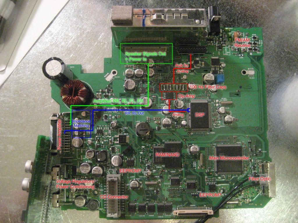
Picking up the front speaker channels at the X9331 connector is not that big a problem.
If you go for the HIFI option, the X9331 connector has full signal for front and back channels. I've run that into an amp to run front and back speakers. With PDC I needed the rear speakers to play the warning signals. I added a powered sub. A second amp for a high quality sub is even better, but more $$ and power drain.
If you go for the HIFI option, the X9331 connector has full signal for front and back channels. I've run that into an amp to run front and back speakers. With PDC I needed the rear speakers to play the warning signals. I added a powered sub. A second amp for a high quality sub is even better, but more $$ and power drain.

6th Gear
Joined: Sep 2007
Posts: 1,342
Likes: 4
From: Youngsville, NC, USA
I think I will upgrade my speakers and maybe add an under the seat amp sub thing.
I'm not an aduiophile. I can hear the difference between my crx radio (base blaupunkt and infinity speakers) and the mini (sounds like broadcasting in mud after listening in).
But I doubt after upgrading the MINI I can tell the difference much.
I just want to get in the car and not go
BLECK
when i turn on the radio.
I doubt I even needed the speaker wire swap which I did.
Although I could tell a difference.

6th Gear
Joined: Apr 2008
Posts: 1,303
Likes: 12
From: Twin Cities, Minnesota
I found the real cure for this issue!
The software you need is NCS Expert with the latest R56 files. You change the radio module parameter VEHICLE_FILTERS to "r 56_hifi" as opposed to the "r 56_stereo"
Plus it looks like you can change the gong sound lots of other things. I have not yet attempted this but I am just learning at the moment.
6th Gear
Joined: Apr 2008
Posts: 1,303
Likes: 12
From: Twin Cities, Minnesota
Bimmerforums under Diagnostic software. This is not an easy undertaking at all. I still haven't actually tried to code anything yet. But I will report back when I do. I am going to try to use this software to add the factory bluetooth/USB module (and try to get rid of or extend the seat belt warning). You will need a D-CAN interface cable as well.

In theory, this sounds great. But has anyone run their hifi equipped car without the hifi present? I vaguely recall seeing posts where this caused issues. If so that might mean the car will not be happy if it's told "hifi" and there is no hifi.
If this does work, this will be great, so I'll be watching this post to see your progress reports.
Good luck!
If this does work, this will be great, so I'll be watching this post to see your progress reports.
Good luck!