
How To Drivetrain :: Operation Vacuum Gain System (VGS)


Thread Starter
|
6th Gear
Joined: Oct 2002
Posts: 3,652
Likes: 6
From: Lansdale, PA
Drivetrain :: Operation Vacuum Gain System (VGS)
Details to follow:
The brass vacuum nipple on the downstream side of the BPV is definitely the hardest part to get to. For easiest VGS installation, I'd recommend the following procedure:
ALPHA METHOD
1) Disconnect the short rubber vacuum hose from the diaphragm of the bypass valve, but leave it attached to the lower brass vacuum nipple. Cap off the now-loose end of that hose.
2) Disconnect the (hard plastic with rubber caps on each end) vacuum line from the intake manifold but leave it attached to the fuel pressure regulator.
3) Install a tee in the now-loose end of that vacuum line.
4) Install a short length of vacuum hose between the tee and the nipple on the intake manifold.
5) Intall a long piece of vacuum hose between the remaining branch on the tee and the diaphragm of the bypass valve.
6) Make sure everything is snug and that all your tools are accounted for.
7) Enjoy.
Using the above method, it should be possible (in fact it's definitely possible) to install the VGS without removing the intercooler.
OMEGA METHOD
Last night, I installed the VGS in an '05 MCS and took pics along the way. I removed the intercooler for easier access and better pics.
Tools required:
T30 Torx screwdriver
Scissors or pliers with cutting tool
Curved needlenose pliers (optional)
MINI-specific scan tool (optional)
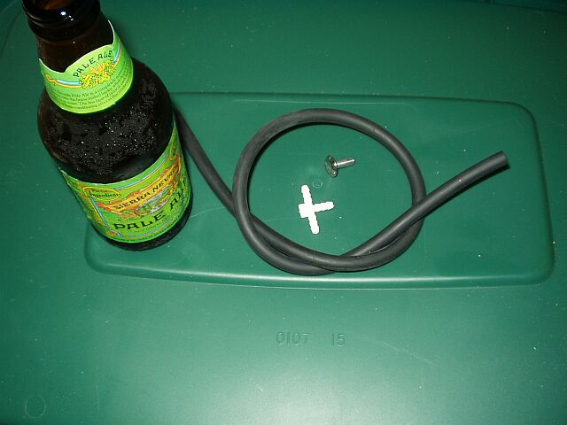
Materials required:
5/32" x 5/32" x 5/32" tee
3 feet of 5/32" ID (5/16" OD) rubber vacuum line
One screw that snugly screws into the vacuum line
Zip tie
Good beer (no Budweiser!)
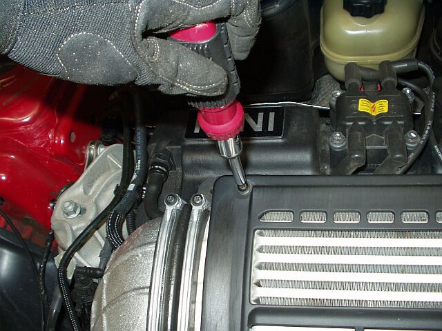
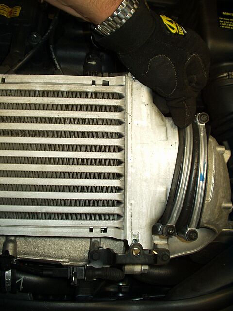
1) Remove the bolts for the IC cover:
2) Loosen but do not remove all four of the T30 Torx bolts for the IC boots:
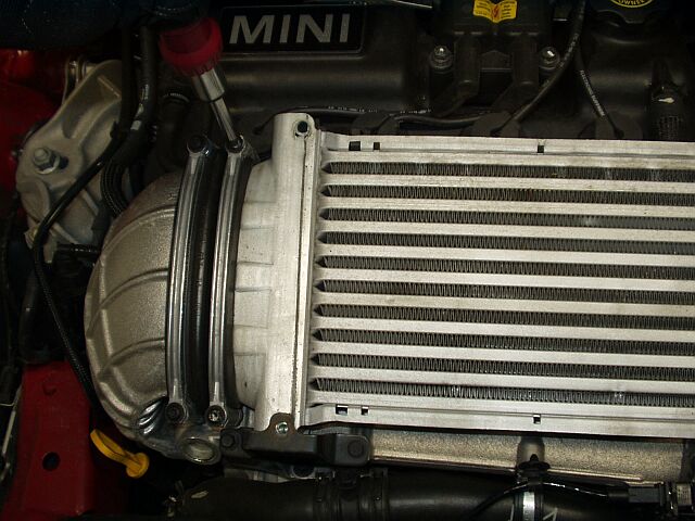
3) Push the smaller IC boot as far to the right as possible and pull the IC toward the windshield and slightly upwards to remove it:
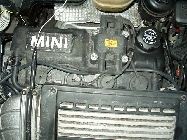
4) Locate the Bypass Valve (BPV) ... it is the black cylinder in the center top of this pic:
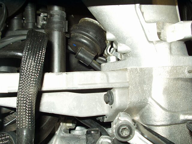
5) Grasp the bypass line and push it toward the front of the car to remove it from the BPV:
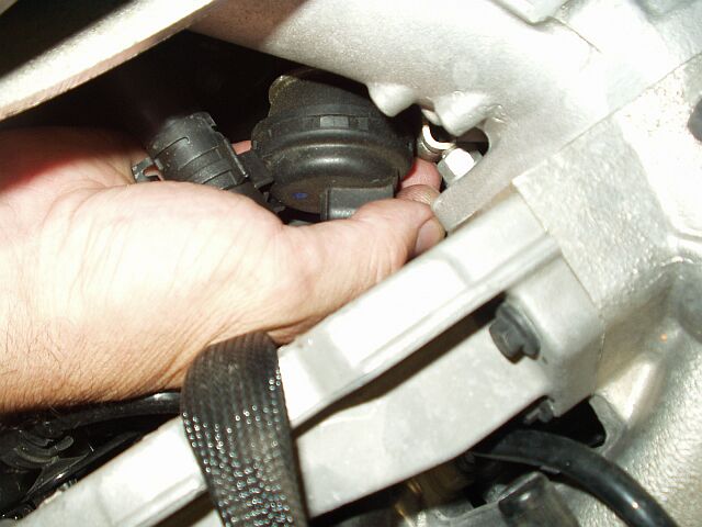
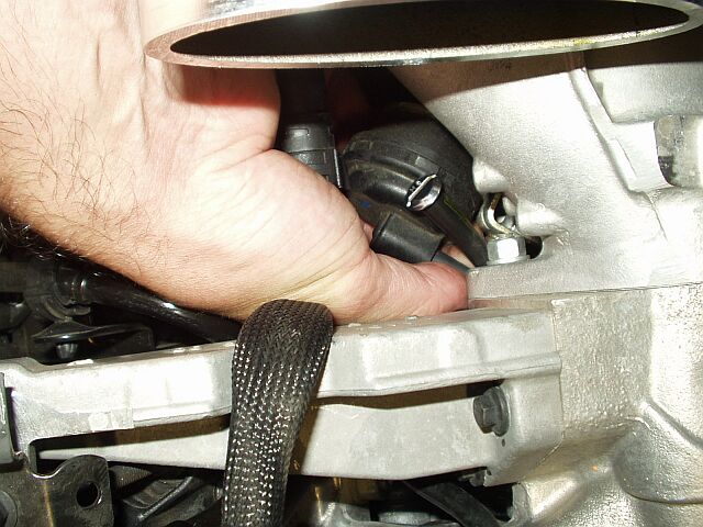
6) Insert a snug-fitting screw into the stock bypass line to cap it off:
7) Slide your long VGS line onto the BPV nipple in the same way you removed the stock one:
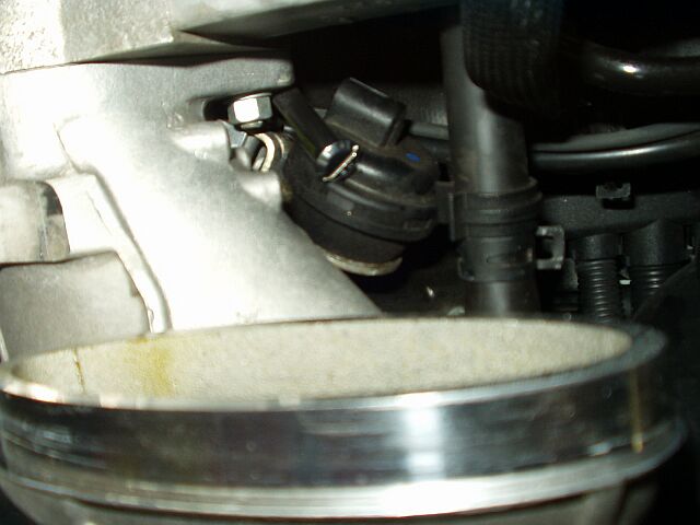
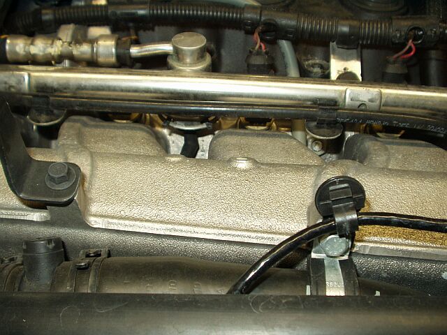
8) Locate the Fuel Pressure Regulator (FPR) in the fuel rail on top of the intake manifold (the silver cylinder in the center top of this pic) and note the rubber elbow attached underneath:
9) Reach under the FPR and push the rubber elbow downwards to remove it from the FPR nipple:
10) Slide one end of the small new vacuum hose (about 8") upwards onto the FPR nipple and make sure the other end of the small new hose is accessible:
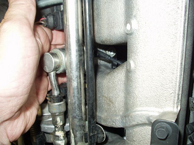
11) Attach the rubber elbow (stock FPR hose) to one end of the tee and the loose end of the new short hose to another end of the tee:
12) Neatly run the long new hose from the BPV to the tee location and attach the loose end of that hose to the tee and zip-tie the tee in place:
13) Inspect your work and make sure all connections are snug and that all of your tools are accounted for:
14) Reinstall the IC and tighten all of the bolts on the rubber boots, making sure to run your fingers behind the IC to make sure all of the boots are in place before starting the car:
15) Start car, listen for vacuum leaks, make sure the idle is stable and scan for fault codes:
16) Enjoy.
The brass vacuum nipple on the downstream side of the BPV is definitely the hardest part to get to. For easiest VGS installation, I'd recommend the following procedure:
ALPHA METHOD
1) Disconnect the short rubber vacuum hose from the diaphragm of the bypass valve, but leave it attached to the lower brass vacuum nipple. Cap off the now-loose end of that hose.
2) Disconnect the (hard plastic with rubber caps on each end) vacuum line from the intake manifold but leave it attached to the fuel pressure regulator.
3) Install a tee in the now-loose end of that vacuum line.
4) Install a short length of vacuum hose between the tee and the nipple on the intake manifold.
5) Intall a long piece of vacuum hose between the remaining branch on the tee and the diaphragm of the bypass valve.
6) Make sure everything is snug and that all your tools are accounted for.
7) Enjoy.
Using the above method, it should be possible (in fact it's definitely possible) to install the VGS without removing the intercooler.
OMEGA METHOD
Last night, I installed the VGS in an '05 MCS and took pics along the way. I removed the intercooler for easier access and better pics.
Tools required:
T30 Torx screwdriver
Scissors or pliers with cutting tool
Curved needlenose pliers (optional)
MINI-specific scan tool (optional)
Materials required:
5/32" x 5/32" x 5/32" tee
3 feet of 5/32" ID (5/16" OD) rubber vacuum line
One screw that snugly screws into the vacuum line
Zip tie
Good beer (no Budweiser!)
1) Remove the bolts for the IC cover:
2) Loosen but do not remove all four of the T30 Torx bolts for the IC boots:
3) Push the smaller IC boot as far to the right as possible and pull the IC toward the windshield and slightly upwards to remove it:
4) Locate the Bypass Valve (BPV) ... it is the black cylinder in the center top of this pic:
5) Grasp the bypass line and push it toward the front of the car to remove it from the BPV:
6) Insert a snug-fitting screw into the stock bypass line to cap it off:
7) Slide your long VGS line onto the BPV nipple in the same way you removed the stock one:
8) Locate the Fuel Pressure Regulator (FPR) in the fuel rail on top of the intake manifold (the silver cylinder in the center top of this pic) and note the rubber elbow attached underneath:
9) Reach under the FPR and push the rubber elbow downwards to remove it from the FPR nipple:
10) Slide one end of the small new vacuum hose (about 8") upwards onto the FPR nipple and make sure the other end of the small new hose is accessible:
11) Attach the rubber elbow (stock FPR hose) to one end of the tee and the loose end of the new short hose to another end of the tee:
12) Neatly run the long new hose from the BPV to the tee location and attach the loose end of that hose to the tee and zip-tie the tee in place:
13) Inspect your work and make sure all connections are snug and that all of your tools are accounted for:
14) Reinstall the IC and tighten all of the bolts on the rubber boots, making sure to run your fingers behind the IC to make sure all of the boots are in place before starting the car:
15) Start car, listen for vacuum leaks, make sure the idle is stable and scan for fault codes:
16) Enjoy.
Last edited by andy@ross-tech.com; Jun 14, 2005 at 07:32 AM. Reason: Updated Instructions - OMEGA version

3rd Gear
Joined: Dec 2004
Posts: 260
Likes: 0
From: Los Angeles, CA
I don't know a lot about MAP, but as with most things (besides rollercoasters and yo-yo's) linear is better than up-and-down. With this "device" are you also able to avoid tripping the MAP sensor since you are staying within tolerances? I guess I'll have to wait for the details...

Thread Starter
|
6th Gear
Joined: Oct 2002
Posts: 3,652
Likes: 6
From: Lansdale, PA
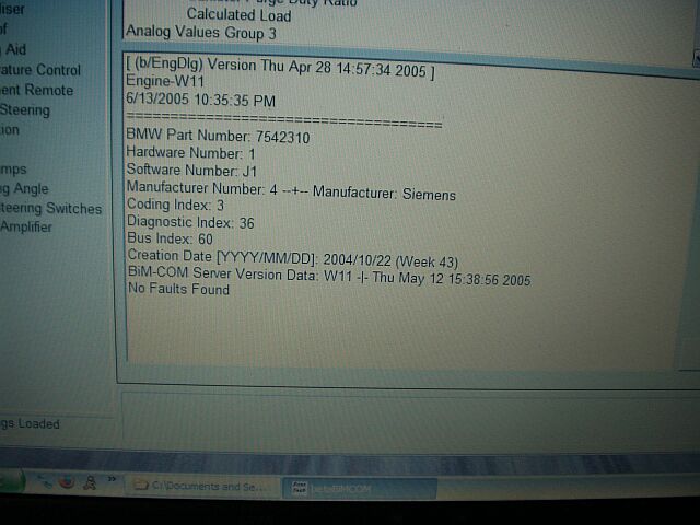
In response to experiencing Yo-Yo as detailed by Ryephile here, I experimented with disabling the bypass valve to avoid the 0-5 psi oscillation. It worked, but as Ryephile found, it set off a fault code for the upstream MAP:
2/23/2005 12:25:08 PM
====================================
Fault Codes Found: 1
----------------------------------------------------------
Fault Code 0x1237 (4663)
SECONDARY UPSTREAM MANIFOLD AIR PRESSURE SENSOR LOW INPUT
----------------------------------------------------------
Short to Ground
Sporadic Error - Repair Sporadic Immediately !
Warning Lamp State
Fault Code Count 31
Distance Since Last MIL, DBW, or EP 4.20Km
Intake Manifold Absolute Pressure 176.48 hPa
Upstream Manifold Pressure 109.97 hPa
Throttle Opening 0.47 TPS Deg
Engine Speed 2795.00 rpm
----------------------------------------------------------
From logging MINI-specific OBD data (far above and beyond the limitations of generic OBD-II), it looks like the upstream MAP sees a min value of about 50 mbar lower pressure with the bypass tied than with it operating in the normal manner (109 mbar -vs- 159 mbar). Combined with the observe loss in fuel economy, Ryephix#1 did not seem worth it to me, although it did definitely get rid of the yo-yo.
Thinking about how short the distance is between the bypass valve and the vacuum source that operates it, I tried a different experiment yesterday. I capped off the bypass valve's vacuum nipple. Then, I put in another Tee where I had tapped into the FPR's vacuum line for my boost gauge. I ran a vacuum line from that tee to the bypass valve.
So, now, instead of seeing the same type of vacuum as the upstream MAP, the bypass valve diaphragm now sees the pressure as seen by the downstream MAP. The result is remarkably similar to tying the bypass valve shut. No oscillation at all in the 0-5 psi range. I didn't notice any elsewhere either. I plan to install a check valve to prevent the bypass diaphragm from seeing boost.
In 5 minutes time, the oscillation is definitely gone, the bypass is definitely open at idle, and less than $5 is missing from my wallet (Tee, vacuum cap, hose). [img]images/smilies/thumb-up.gif[/img]
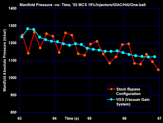
The above log represents part-throttle in second gear, trying to hold boost at about 3 psi as best I could. You can see that the VGS does a MUCH better job than the stock bypass configuration (stock you can really feel those +/- 100 mbar swings!). According to Ryephile, the stock bypass valve is "full open at 15 in-Hg and full closed at about 1 in-Hg". This corresponds to a range of 491-965 mbar absolute. With the VGS, instead of seeing 550-700 mbar in the "yo-yo zone", it now sees 1000-1200 mbar and is thus, fully closed. When not under boost, it should be almost fully open during normal cruising, ensuring fuel economy much better than with Ryephix#1.
I'll keep track of my fuel consumption over the next few tanks to see how well this theory holds up. For now, my boost is steady and the VGS is staying on my MCS. :smile:
2/23/2005 12:25:08 PM
====================================
Fault Codes Found: 1
----------------------------------------------------------
Fault Code 0x1237 (4663)
SECONDARY UPSTREAM MANIFOLD AIR PRESSURE SENSOR LOW INPUT
----------------------------------------------------------
Short to Ground
Sporadic Error - Repair Sporadic Immediately !
Warning Lamp State
Fault Code Count 31
Distance Since Last MIL, DBW, or EP 4.20Km
Intake Manifold Absolute Pressure 176.48 hPa
Upstream Manifold Pressure 109.97 hPa
Throttle Opening 0.47 TPS Deg
Engine Speed 2795.00 rpm
----------------------------------------------------------
From logging MINI-specific OBD data (far above and beyond the limitations of generic OBD-II), it looks like the upstream MAP sees a min value of about 50 mbar lower pressure with the bypass tied than with it operating in the normal manner (109 mbar -vs- 159 mbar). Combined with the observe loss in fuel economy, Ryephix#1 did not seem worth it to me, although it did definitely get rid of the yo-yo.
Thinking about how short the distance is between the bypass valve and the vacuum source that operates it, I tried a different experiment yesterday. I capped off the bypass valve's vacuum nipple. Then, I put in another Tee where I had tapped into the FPR's vacuum line for my boost gauge. I ran a vacuum line from that tee to the bypass valve.
So, now, instead of seeing the same type of vacuum as the upstream MAP, the bypass valve diaphragm now sees the pressure as seen by the downstream MAP. The result is remarkably similar to tying the bypass valve shut. No oscillation at all in the 0-5 psi range. I didn't notice any elsewhere either. I plan to install a check valve to prevent the bypass diaphragm from seeing boost.
In 5 minutes time, the oscillation is definitely gone, the bypass is definitely open at idle, and less than $5 is missing from my wallet (Tee, vacuum cap, hose). [img]images/smilies/thumb-up.gif[/img]
The above log represents part-throttle in second gear, trying to hold boost at about 3 psi as best I could. You can see that the VGS does a MUCH better job than the stock bypass configuration (stock you can really feel those +/- 100 mbar swings!). According to Ryephile, the stock bypass valve is "full open at 15 in-Hg and full closed at about 1 in-Hg". This corresponds to a range of 491-965 mbar absolute. With the VGS, instead of seeing 550-700 mbar in the "yo-yo zone", it now sees 1000-1200 mbar and is thus, fully closed. When not under boost, it should be almost fully open during normal cruising, ensuring fuel economy much better than with Ryephix#1.
I'll keep track of my fuel consumption over the next few tanks to see how well this theory holds up. For now, my boost is steady and the VGS is staying on my MCS. :smile:

Thread Starter
|
6th Gear
Joined: Oct 2002
Posts: 3,652
Likes: 6
From: Lansdale, PA
Trending Topics

Thread Starter
|
6th Gear
Joined: Oct 2002
Posts: 3,652
Likes: 6
From: Lansdale, PA
Cliff notes:
Instead of using "upstream vacuum, ie. pre-supercharger" to control the bypass valve, this new system uses "downstream vacuum, ie. post-supercharger" to control the bypass valve. In practice, this gives wicked fast bypass valve response, no yo-yo, and (unlike any other method out there) actually holds the bypass valve closed with more force the more boost you see.
The VGS gains vacuum by getting it from a different source than stock.
Thread Starter
|
6th Gear
Joined: Oct 2002
Posts: 3,652
Likes: 6
From: Lansdale, PA
Originally Posted by Zociac
Andy,
If I install both the M7 Air Gain System and your Vacuum Gain System , should I expect no performance gain?
Doesn't your vacuum gain sucks all the air gained from the AGS?

If I install both the M7 Air Gain System and your Vacuum Gain System
, should I expect no performance gain?Doesn't your vacuum gain sucks all the air gained from the AGS?

4th Gear
Joined: Dec 2002
Posts: 314
Likes: 1
From: Sammamish, WA
Andy,
Does the bypass valve operate in the normal and intended manner in the off idle driving range with this modified vacuum source method ? I'd am very interested in making the change if I can retain the same gas mileage and low speed performance of the stock arrangement and still avoid that dreaded yo-yo.
Regards,
John Petrich in Seattle
Thread Starter
|
6th Gear
Joined: Oct 2002
Posts: 3,652
Likes: 6
From: Lansdale, PA
I'd say it now operates in a more normal matter than stock. Under vacuum, the valve opens up, while under boost it remains closed. I wouldn't be surprised if mileage suffers a little bit, but even if it does, it's worth it, IMHO.

6th Gear
Joined: Apr 2004
Posts: 1,179
Likes: 0
From: San Francisco Ca.
Right on Andy, thanks for coming up with this. How has your gas mileage been so far?
No harm meant btw, I was just sharing my view on certain things. Glad you were able to start this again.
James
No harm meant btw, I was just sharing my view on certain things. Glad you were able to start this again.
James
Originally Posted by andy@ross-tech.com
I'd say it now operates in a more normal matter than stock. Under vacuum, the valve opens up, while under boost it remains closed. I wouldn't be surprised if mileage suffers a little bit, but even if it does, it's worth it, IMHO.

6th Gear

Joined: Jul 2002
Posts: 2,228
Likes: 28
From: Bishop, Ca
Andy, Could you go into alittle more detail on the routing, and which lines to splice into. I printed out your pictures, then got completly lost when I went to try to figure out how to do this.
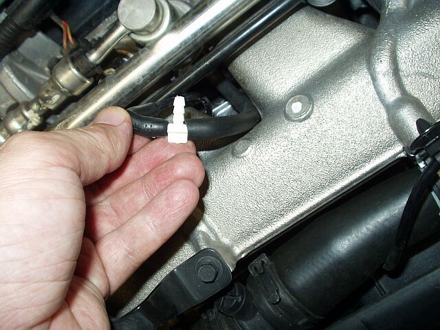
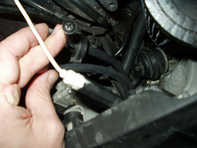
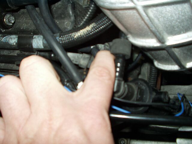
Pic 1: The hose that is plugged is it the one that comes thru the clamp just below your fingure? and is the hose by your thumb in the same picture the one you added that runs across the valve cover?
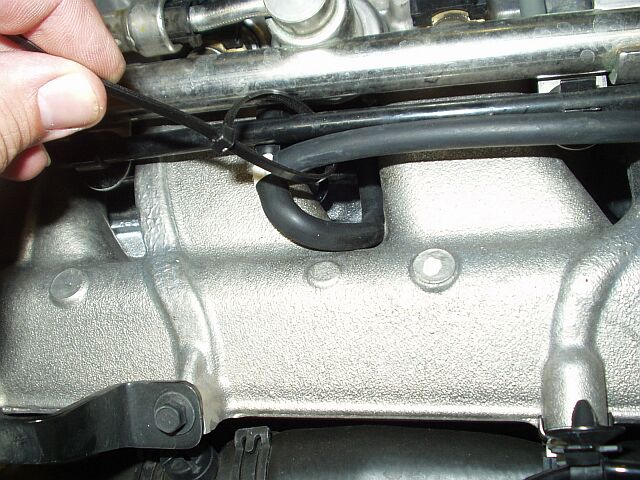
Pic 2: Got that one figured out. I know genius
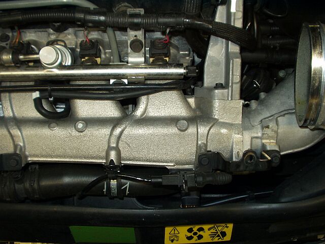
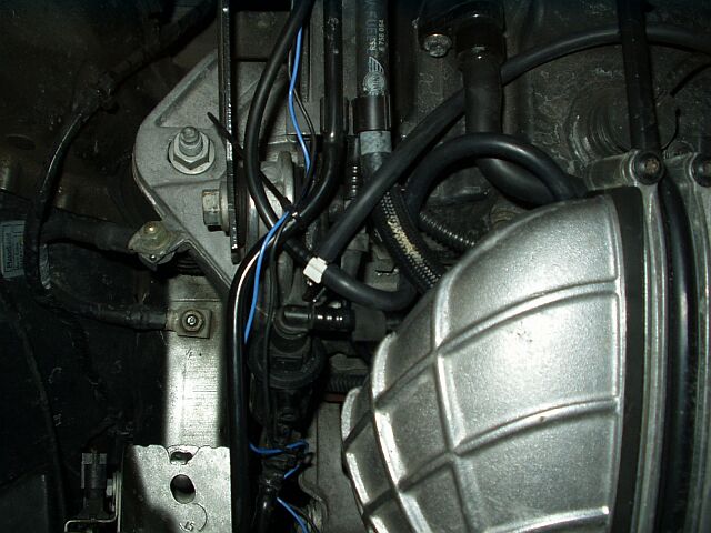
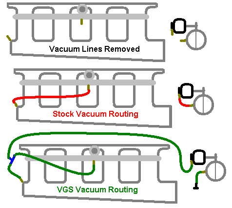
Pic 3:Center of the white "T" goes across the valve cover to the other side. Correct?
Right side of "T" goes?
Left side of "T" comes from where?
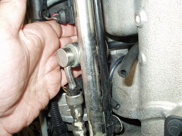
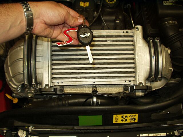
Pic 4: Watcha pointing at? Is that the grey tube that comes from the SC? That would be capped off if you have a catch can?
I'm obviously not as framilier with this engine as you are, but trying to learn. Cant wait to try the VGS out.
Thanks,
Nik
Pic 1: The hose that is plugged is it the one that comes thru the clamp just below your fingure? and is the hose by your thumb in the same picture the one you added that runs across the valve cover?
Pic 2: Got that one figured out. I know genius
Pic 3:Center of the white "T" goes across the valve cover to the other side. Correct?
Right side of "T" goes?
Left side of "T" comes from where?
Pic 4: Watcha pointing at? Is that the grey tube that comes from the SC? That would be capped off if you have a catch can?
I'm obviously not as framilier with this engine as you are, but trying to learn. Cant wait to try the VGS out.
Thanks,
Nik
Thread Starter
|
6th Gear
Joined: Oct 2002
Posts: 3,652
Likes: 6
From: Lansdale, PA
Originally Posted by sfjames2
He's blowing smoke man.
Originally Posted by Ryephile
Ok - why wouldn't you be suprised?
Originally Posted by nabarbieri
Andy, Could you go into alittle more detail on the routing, and which lines to splice into. I printed out your pictures, then got completly lost when I went to try to figure out how to do this.
There is a vacuum nipple on the intake manifold:
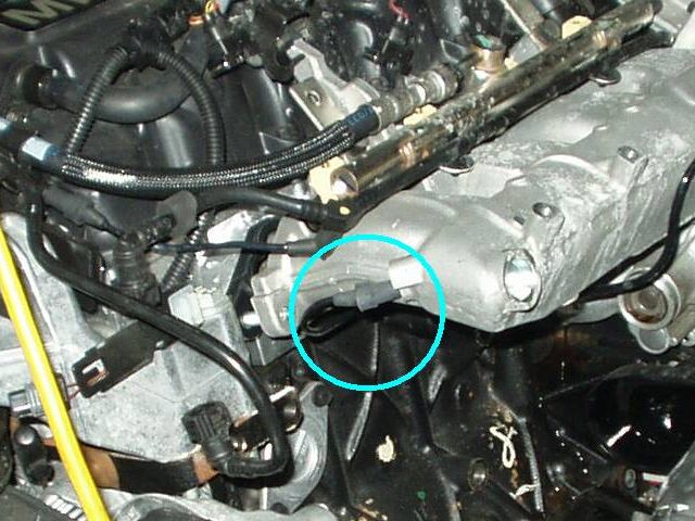
Connected to this nipple is a vacuum line that runs to the fuel pressure regulator (FPR). I unplugged that line from the manifold nipple, but left the other end plugged into the FPR. I attached the loose end to a 5/32" vacuum tee. Using a small piece of vacuum line (12" would be plenty), I connected one end to the vacuum tee and the other end to the manifold nipple. It's not super easy to get to, but it can be done by feel, just make sure the engine is cool when you do it.
On the other side of the engine, I removed the short vacuum line from the bypass valve (this is the piece that the "M7 Device" replaces). I attached a short length of vacuum hose (6" or so) to the vacuum nipple on the bottom of the bypass valve. At the end of this hose, I screwed a small screw to seal off the hose. You could always just use a vacuum cap, but I wanted to leave enough room to be able to quickly and easily swap this back and forth with stock for testing. To swap back to stock, all I'd need to do is swap the screw for the bypass diaphragm nipple and vice versa for the short and long vac lines.
Again, it's not super easy to get to, but it can be done by feel, just make sure the engine is cool when you do it.
I ran a length of vacuum hose (not sure of the exact length, but 36" would be plenty) from the diapghragm nipple on the bypass valve to the remaining barb on the tee that was installed on the passenger side of the engine. I may try a one-way check valve in the long vacuum line to prevent the bypass diaphragm from seeing boost, but I'm not sure if this is needed.
I can draw a diagram if it would help to understand what is getting plugged in where.
Last edited by andy@ross-tech.com; Feb 27, 2005 at 10:27 AM. Reason: typo
Andy, Vacuum routing Questions
"Connected to this nipple is a vacuum line that runs to the fuel pressure regulator (FPR). I unplugged that line from the manifold nipple, but left the other end plugged into the FPR. I attached the loose end to a 5/32" vacuum tee. Using a small piece of vacuum line (12" would be plenty), I connected one end to the vacuum tee and the other end to the manifold nipple. It's not super easy to get to, but it can be done by feel, just make sure the engine is cool when you do it."
Is this also where you are getting your boost gage source?
"On the other side of the engine, I removed the short vacuum line from the bypass valve (this is the piece that the "M7 Device" replaces). I attached a short length of vacuum hose (6" or so) to the vacuum nipple on the bottom of the bypass valve. At the end of this hose, I screwed a small screw to seal off the hose."
This I take is the vacuum source for the bypass valve diaphragm?
"You could always just use a vacuum cap, but I wanted to leave enough room to be able to quickly and easily swap this back and forth with stock for testing. To swap back to stock, all I'd need to do is swap the screw for the bypass diaphragm nipple and vice versa for the short and long vac lines."
Or the vacuum source could be used with a switch to turn on an intercooler sprayer.
"I ran a length of vacuum hose (not sure of the exact length, but 36" would be plenty) from the diapghragm nipple on the bypass valve to the remaining barb on the tee that was installed on the passenger side of the engine. I may try a one-way check valve in the long vacuum line to prevent the bypass diaphragm from seeing vacuum, but I'm not sure if this is needed."
This last sentence about, "the bypass diaphragm from seeing vacuum" has me asking don't we want to see vacuum at partial or anything other than WOT so the bypass continues to operate. I think the question was asked about the bypass diaphragm seeing boost pressure which may have a neg. effect on the bypass diaphragm, meaning a one way check valve would be in order so that it only see's a vacuum.
"I can draw a diagram if it would help to understand what is getting plugged in where."
Please do! Thanks for sharing your discovery.
Last edited by norm03s; Feb 27, 2005 at 01:40 PM. Reason: stupid spelling error