
Electrical Questions on Hella 500 Black Magic Driving Lights Install

Thread Starter
|
2nd Gear
Joined: Apr 2011
Posts: 92
Likes: 0
From: Shelby Township, MI
Questions on Hella 500 Black Magic Driving Lights Install
I'm really new at modifying electrical parts on cars, so please bear with me. I took on this project thinking it would be a new experience, and so far it has been. I used the OutMotoring brackets shown here:

At first, I thought that I had bitten off more than I could chew, but I soon figured out how to connect wires together and even connect the wires to the relay box (even though I still don't know exactly what it does). It was like learning a new language. Anyway, after a few hours of connecting wires, threading wires, and poking my finger with wires, and I found an impasse seemingly reaching my limit of electrical knowledge.
If you notice in the instructions below, it calls for the switch to be connected to power source as well as being grounded. The grounding part I can work with, but I don't exactly know what power source to connect the green wire to. I see that it points to the headlamps, but I'm unsure what wire/source it refers too.
 Also, I'm having trouble deciding on a place to put the switch for the driving lights. Here is a picture of the switch with the green power wire:

I know that the factory driving light switch is installed on the driver's side knee bolster. If there is anyone with experience with this specific driving light, it would be very appreciated. Also, if you could speak slowly because my electrical dialect is rather poor TIA
TIA
At first, I thought that I had bitten off more than I could chew, but I soon figured out how to connect wires together and even connect the wires to the relay box (even though I still don't know exactly what it does). It was like learning a new language. Anyway, after a few hours of connecting wires, threading wires, and poking my finger with wires, and I found an impasse seemingly reaching my limit of electrical knowledge.
If you notice in the instructions below, it calls for the switch to be connected to power source as well as being grounded. The grounding part I can work with, but I don't exactly know what power source to connect the green wire to. I see that it points to the headlamps, but I'm unsure what wire/source it refers too.
I know that the factory driving light switch is installed on the driver's side knee bolster. If there is anyone with experience with this specific driving light, it would be very appreciated. Also, if you could speak slowly because my electrical dialect is rather poor
TIA
6th Gear
Joined: Nov 2004
Posts: 2,607
Likes: 316
From: Arnold, MO.
The power source for the switch comes from your fuse box, the accessory fuse (don't remember the position), it basicly is power only when the ignition/key is on.
You could of course hook it up direct, but then the lights would work "anytime" not good if you accidently turn them on in the day time & park your car for any length of time.
You could of course hook it up direct, but then the lights would work "anytime" not good if you accidently turn them on in the day time & park your car for any length of time.
Last edited by BlwnAway; Dec 16, 2012 at 08:14 AM.
Thread Starter
|
2nd Gear
Joined: Apr 2011
Posts: 92
Likes: 0
From: Shelby Township, MI
So I looked up what BlwnAway had called an "accessory fuse" in the MINI Cooper service manual and only could come up with a few possibilities. According to the manual, in fuse panel 2, which is behind the left kick panel, there aren't any fuses labeled "accessory fuse". So I'm guessing he is referring to the fuse panel next to the left strut tower. This one has two possibilities with fuses that are connected to the headlights: FL8 and FL12. Both are labeled "General Module (BC1); lights", so I'm concluding that I can connect the power wire for the switch to either one.
My only problem, if I'm right so far, is how to do so. I found this blue piece with the rest of the installation equipment. Since it is the only piece that I haven't used, I'm guessing that this piece is used for connecting to a fuse:


Anybody got any idea on where I go from here?
My only problem, if I'm right so far, is how to do so. I found this blue piece with the rest of the installation equipment. Since it is the only piece that I haven't used, I'm guessing that this piece is used for connecting to a fuse:
Anybody got any idea on where I go from here?
Last edited by MINIng; Dec 16, 2012 at 02:55 PM.

the little blue goody is use to splice into a wire, the are two sides, one side is open and goes on the wire you want to tap, the other side is only open on one side that one takes the wire from your lights-squeeze the metal piece down into the wires and then cllick the band around it to hold it closed
Thread Starter
|
2nd Gear
Joined: Apr 2011
Posts: 92
Likes: 0
From: Shelby Township, MI
oohhh so this piece allows me to splice into the high beams, but i'm not going in that direction.
so do you think that I'm going in the right direction with the fuses to power the switch?
if so, then I'll need to get a fuse tap right?
so do you think that I'm going in the right direction with the fuses to power the switch?
if so, then I'll need to get a fuse tap right?
6th Gear
Joined: Nov 2004
Posts: 2,607
Likes: 316
From: Arnold, MO.
Drivers side kick panel Fuse Panel, position F-39, battery source / key on hot. (tap into the side closest to the firewall, not the side closest to the door.)
Either go to your local Auto Parts store & buy the adapter to tap into the fuse panel, (just tell them what you're doing, they'll help) or do like us non-professionals do, strip about 1/4 to 3/8 of the end of the wire, (you want it to be double the length of the metal spade on the fuse) flatten it out & bend it around the end of the spade, push it back in place. Not technically correct, but it works.
*Personally, I like mine just on the key'd power, so that I can choose to use them w/ or w/o the High Beams, that way "I" can choose the combination of lights I have on at any given time.
Trending Topics
Thread Starter
|
2nd Gear
Joined: Apr 2011
Posts: 92
Likes: 0
From: Shelby Township, MI
Thanks for the reply. and yeah, i'm shooting for that ability as well.
my bentley manual says that the f39 fuse is for the alternator/electric power steering pump. The label on my fuse panel kickoff states that F38 is for the battery, but my manual doesn't even acknowledge any f-38. The label also says the fuse should be a 5 amp when it is instead 10 amp fuse. i sure hope i do this right cuz i would hate if they stopped working...lol
i tried doing the non-pro way and i ended up cutting off so much wire from my mess up, i'm just going to wait until radioshack opens up tomorrow and see where it all goes from there.
Last edited by MINIng; Dec 16, 2012 at 05:17 PM. Reason: confusion
6th Gear
Joined: Nov 2004
Posts: 2,607
Likes: 316
From: Arnold, MO.
All I have to go by is the panel on my '05, its the last run of fuses, the short run, 3rd one down, (2nd one is empty) corresponds on mine with a picture of a battery on the cover, since you're just powering a relay, any key/on fuse would actually do, since you're not actually drawing power for the lights themselves from there, the relay takes hardly any juice at all.

1st Gear
Joined: Nov 2011
Posts: 48
Likes: 0
From: Delta, BC Canada
Another route you can go is to tap into the gauge illumination wire - it is in the thick bundle that goes from the fuse panel in the passenger compartment. Gray with red stripe - there are two of them - choose the smaller gauge one. Use the blue tap supplied with your kit. This will provide you with power to the switch whenever the lights are turned on. That way you can choose to switch on the driving lamps whenever you like (not just high beams) which I think is what you want.
Thread Starter
|
2nd Gear
Joined: Apr 2011
Posts: 92
Likes: 0
From: Shelby Township, MI
Okay, so I hooked everything up, using the battery fuse for power for the switch. BUT, something must have gone wrong. I turned the key over and no light for the switch and nothing from the lights when I turned it on. So I took some pics to see if you guys could help me troubleshoot.
Here is a pic of the set-up from the engine bay. The black wire from the driving lights travels behind the engine cover:

I grounded the two driving lights here:

Here is a pic of what I think is the relay box. The red connects to the battery. The blue is grounded. The yellow travels through the firewall to the switch. The black goes to the driving lights:

Here is a pic of the red wire connected to the battery terminal next to the air box:

Here is a pic of the set up underneath the steering column. Again, the yellow connects the relay to the switch. The green connects the switch to the fuse. The blue grounds.

Here is a pic of the wires connecting to the switch. Do these look right?

Here is the pic of the green wire connecting to the fuse. I used the blade fuse tap:

So, if everything looks good to you guys, I guess I'll do the long and arduous task of checking all the connections. I just want to make sure that this set-up is doable.
Here is a pic of the set-up from the engine bay. The black wire from the driving lights travels behind the engine cover:
I grounded the two driving lights here:
Here is a pic of what I think is the relay box. The red connects to the battery. The blue is grounded. The yellow travels through the firewall to the switch. The black goes to the driving lights:
Here is a pic of the red wire connected to the battery terminal next to the air box:
Here is a pic of the set up underneath the steering column. Again, the yellow connects the relay to the switch. The green connects the switch to the fuse. The blue grounds.
Here is a pic of the wires connecting to the switch. Do these look right?
Here is the pic of the green wire connecting to the fuse. I used the blade fuse tap:
So, if everything looks good to you guys, I guess I'll do the long and arduous task of checking all the connections. I just want to make sure that this set-up is doable.
6th Gear
Joined: Nov 2004
Posts: 2,607
Likes: 316
From: Arnold, MO.
Seems right, double check the relay wires positions according to the diagram supplied, also make sure I was correct on the "side" of the fuse to tap into, I was just going by memory. If that's not it, start chasing power with a test light, starting at the fuse panel, and both sides of your fuse links incase a fuse is not only blown & you can't see it, but to make sure it's connecting properly inside the holder, you already know the wire from the battery junction post is hot, so you know that that is good.
Thread Starter
|
2nd Gear
Joined: Apr 2011
Posts: 92
Likes: 0
From: Shelby Township, MI
So I ran a test light on the fuse connection for the fuse panel. Its the connection for the switch. When the key is in the accessory position, it lights ups. So we're good there. 
However, I tested the end of the green power wire for the switch. No good.
So then that led me to test the fuse in the power wire. No good.
Then I thought about testing the end of the wire before the fuse. No good.
Then I switch the fuses between the green and the red wire fuse which connects to the battery terminal and tested the connection in the red wire. GOOD.
Soooo, Does this mean that the green wire is faulty since the fuse tested good in red wire?
6th Gear
Joined: Nov 2010
Posts: 2,466
Likes: 2
From: Savannah Georgia
Now you'll want to replace those nasty yellow hallogen lights with HIDs!!! It'll be a little more wiring.
H3C HID Kit
H3C HID Kit
Thread Starter
|
2nd Gear
Joined: Apr 2011
Posts: 92
Likes: 0
From: Shelby Township, MI
Please, one headache at a time... lol.
I tried the connection to the fuse jumper and it was unfortunately good. My first time adding electrical upgrades isn't going very well. I guess I'll have to go get new electrical wiring tomorrow, which really pisses me off because the wiring came with the set. That don't make no sense.
I tried the connection to the fuse jumper and it was unfortunately good. My first time adding electrical upgrades isn't going very well. I guess I'll have to go get new electrical wiring tomorrow, which really pisses me off because the wiring came with the set. That don't make no sense.
6th Gear
Joined: Nov 2004
Posts: 2,607
Likes: 316
From: Arnold, MO.
Ha, Ha, first off don't let electrical freak you out, as confusing as it seems on the outside, it's all very basic, and normally troubleshooting is 90% time consuming, and yes, sucks worse if you simply end up with a bad component (wire / connector / fuse), esp. your first time out.
Before you spend any money do these simple things first:
1. Pull the fuse & fuse panel jumper from the fuse panel.
2. Use your test light and check to be certain which side on the fuse panel is hot & which side is cold
3. Replace the fuse & jumper, with the jumper on the "cold" side of the fuse.
4. Cut the green wire just "after" the in-line fuse holder. (basicly you're just removing the in-line fuse & the first section of wire from the equation)
5. Strip some of the shielding from the end you just cut, that is still attached to the switch.
6. Attach this to the fuse panel jumper. (just use a piece of electrical tape to hold it in place temporarily)
Check to see if this corrects your problem, if so, then pick up another fuse box jumper or re-use the one you have if you can & permanently wire it as such. (Since you're only powering a relay the in-line fuse on the green wire is not really needed, plus this is the reason for using the "cold" side of the fuse panel as the connection, the fuse in the panel now acts as the fuse for that wire, and again, the draw should be so small that the current fuse in the panel should still be adequate.
Last edited by BlwnAway; Jan 9, 2013 at 05:37 AM.

OVERDRIVE
Joined: Jul 2006
Posts: 7,037
Likes: 283
From: Melbourne, FL
Use your test light and check to be certain which side of the fuse is hot & which side is cold
how exactly do you have a hot side and a cold side of a fuse? If the fuse is intact, and power is applied it is hot on both sides. Only if the fuse is blown, do you have a hot and a cold side; aka an open circuit!
You're describing a switch ... not a fuse. On a fused switched circuit the switch must happen b4 or after the fuse but is not IN the fuse .. . .
to OP who does not understand what the relay does: The relay is an electric switch; its purpose is to keep the full 'juice' needed to power the accessory (in this case lights) away from the control switch (which you are adding) because the switch is not designed to carry the full load (amps) and would burn up.
The relay's poles 30 and 87 are the path for the full amperage 'juice' from the power supply (often the battery) to the accessory (lights). There is an on/off function in the relay for this path controlled by the pole pair 85 and 86. When 85-86 has power applied, the 30-87 relay path is ON and the lights power up. When 85-85 has no power the relay is open or OFF - no lights. The 85-86 path is where you add your button of toggle to control the flow to the 'control side' of the relay . . . . the control side needs very little amps
or try: http://www.thenewx.org/forum/showthread.php?t=28282
{I've installed many sets of driving lights for folks using relays, as well as horns both in place of and in addition to the factory horns. Did a set of big Hellas for a guy just last week. I have Hellas and a set of 5 air horns in my 79 - on a relay, with a toggle to select which set sounds when I push the factory horn button . . . all the wiring is essentially the same
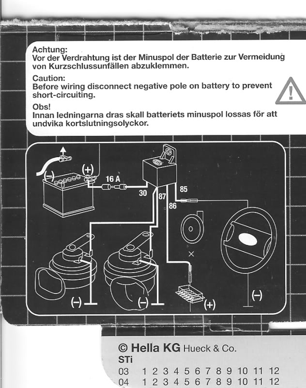
OP has an extra ground wire in his switch (steering wheel in this diagram) because the switch is itself illuminated, drawing power from the trigger circuit 85-86 as well}
how exactly do you have a hot side and a cold side of a fuse? If the fuse is intact, and power is applied it is hot on both sides. Only if the fuse is blown, do you have a hot and a cold side; aka an open circuit!
You're describing a switch ... not a fuse. On a fused switched circuit the switch must happen b4 or after the fuse but is not IN the fuse .. . .
to OP who does not understand what the relay does: The relay is an electric switch; its purpose is to keep the full 'juice' needed to power the accessory (in this case lights) away from the control switch (which you are adding) because the switch is not designed to carry the full load (amps) and would burn up.
The relay's poles 30 and 87 are the path for the full amperage 'juice' from the power supply (often the battery) to the accessory (lights). There is an on/off function in the relay for this path controlled by the pole pair 85 and 86. When 85-86 has power applied, the 30-87 relay path is ON and the lights power up. When 85-85 has no power the relay is open or OFF - no lights. The 85-86 path is where you add your button of toggle to control the flow to the 'control side' of the relay . . . . the control side needs very little amps
or try: http://www.thenewx.org/forum/showthread.php?t=28282
{I've installed many sets of driving lights for folks using relays, as well as horns both in place of and in addition to the factory horns. Did a set of big Hellas for a guy just last week. I have Hellas and a set of 5 air horns in my 79 - on a relay, with a toggle to select which set sounds when I push the factory horn button . . . all the wiring is essentially the same
OP has an extra ground wire in his switch (steering wheel in this diagram) because the switch is itself illuminated, drawing power from the trigger circuit 85-86 as well}
6th Gear
Joined: Nov 2004
Posts: 2,607
Likes: 316
From: Arnold, MO.
Simple, pull the fuse, one side in the panel is hot, one side is not, if you jumper to the cold side and plug the fuse back in you are now using that fuse as your fuse, if you jumper to the hot side you are not. (and would then need to add an inline fuse)
(I fixed my earlier post to be more clear, guess I should have said "for" the fuse instead of "of" the fuse.)
(I fixed my earlier post to be more clear, guess I should have said "for" the fuse instead of "of" the fuse.)
Last edited by BlwnAway; Jan 9, 2013 at 07:18 AM.

2nd Gear
Joined: Apr 2012
Posts: 123
Likes: 0
From: Bay Area, Ca.
Any updates on this? I have the same set and it didnt work either got so frustrated i got rid of the relay and it worked but after a few uses it blew the fuse. So I guess I need the relay. Can I pick up any type of relay or does it have to be specific? Thanks
Last edited by DVS DEA; Jul 7, 2013 at 09:59 PM.
5th Gear
Joined: Sep 2012
Posts: 699
Likes: 7
You need a relay. A relay is simply a heavy duty switch activated by a lower power circuit.
Not using a relay, as you have found, in the best case blows fuses, in the worst case overloads and burns out wiring, connectors and switches.
You can buy special relays for special purposes, but you just want a regular general purpose automotive one rated to the current you need (general relays are about 30A max).
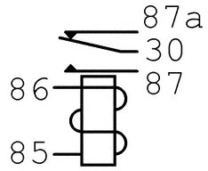
The terminals use these markings.
 .
.
Your switch runs power through 85 and 86. A magnetic field is generated and moves the piece of metal that connects to pin 30 from terminal 87a to 87.
So 30 and 87 are used for the high current lamps. 85 and 86 are used for the switch to activate the relay.
The magnet and the high current side are not directional.
Generally speaking terminal 87 is used as the supply (30A max fused supply) and 30 as the drain (bulb).
In this arrangement 87a can optionally be used to connect additional momentary high current power source eg the high beam flasher, if that's legal in your country and the source has sufficient capacity for the extra current drain.
87a is called the 'normally closed' circuit.
87 is called the 'normally open' circuit.
------------------------------------------------------------------------------------------------------
EDIT: Something like this. You may want to use only IGN switched power for the low current or both side terminals as this will prevent the relay being on at any time and draining the vehicle battery. you can burn 100mA in the coil which can flatten a battery overnight. 20A bulbs would flatten the battery in about 3 hours.

And you can simplify one terminal by using the same feed to power both sides of the coil with a switched negative switch. [bottom diagram, green light are the lamps, yellow light is not used, swap the 'battery' for high current fused Ignition]

Not using a relay, as you have found, in the best case blows fuses, in the worst case overloads and burns out wiring, connectors and switches.
You can buy special relays for special purposes, but you just want a regular general purpose automotive one rated to the current you need (general relays are about 30A max).
The terminals use these markings.
. Your switch runs power through 85 and 86. A magnetic field is generated and moves the piece of metal that connects to pin 30 from terminal 87a to 87.
So 30 and 87 are used for the high current lamps. 85 and 86 are used for the switch to activate the relay.
The magnet and the high current side are not directional.
Generally speaking terminal 87 is used as the supply (30A max fused supply) and 30 as the drain (bulb).
In this arrangement 87a can optionally be used to connect additional momentary high current power source eg the high beam flasher, if that's legal in your country and the source has sufficient capacity for the extra current drain.
87a is called the 'normally closed' circuit.
87 is called the 'normally open' circuit.
------------------------------------------------------------------------------------------------------
EDIT: Something like this. You may want to use only IGN switched power for the low current or both side terminals as this will prevent the relay being on at any time and draining the vehicle battery. you can burn 100mA in the coil which can flatten a battery overnight. 20A bulbs would flatten the battery in about 3 hours.
And you can simplify one terminal by using the same feed to power both sides of the coil with a switched negative switch. [bottom diagram, green light are the lamps, yellow light is not used, swap the 'battery' for high current fused Ignition]
Last edited by joylove; Jul 7, 2013 at 10:43 PM. Reason: added some diagrams.

Thread
Thread Starter
Forum
Replies
Last Post
Interior/Exterior DEPO/Helix Projector Headlights Installed
Alkaidovich
Interior/Exterior
68
Jan 30, 2021 01:35 AM
igzekyativ
MINIs & Minis for Sale
34
Jul 16, 2020 12:54 PM
Wohnson89
R50/R53 :: Hatch Talk (2002-2006)
4
Jun 10, 2020 04:53 AM
jrezzo
MINIs & Minis for Sale
0
Aug 9, 2015 10:32 PM