When you click on links to various merchants on this site and make a purchase, this can result in this site earning a commission. Affiliate programs and affiliations include, but are not limited to, the eBay Partner Network.
I have the dyno results everybody This time I dyno my own car, first time with the printed charge pipe and second time with the oem setup. The intake was exactly the same both times ( filter, air box, air tubes), everything was OEM (only difference was thecharge pipe). I did in total 4 runs each time. 100 RON fuel, close hood same temperature (26 degrees).
Power:
Result.... there is in AVERAGE (4 runs) only 1 hp difference . Of course I can't consider that as a plus or minus.
Average 201 hp.
IAT:
It seems that with the printed model IATs are a bit lower. For example the 4th run : Printed charge pipe MAX=60 C , OEM MAX=63 C
Average values as very close during the whole run.
Average Air Mass kg/h:
4th run
OEM: 403 kg/h
Printed model: 414 kg/h
PSI:
Very close both
Conclusion:
No extra power for sure (that's the easiest to conclude). It seems that with the printed model the engine responded a bit better, lower IATs and maybe it breaths a bit better.
I was surprised that the carbon reinforced nylon printed model could take that abuse! I drove with it 1000 km , including fast driving at the mountain, heavy traffic in Athens with around 30 degrees Celsius outside and 4 dyno pulls So defiantly this material is up to the task and so useful for testing.
What's next?
Two versions:
Long pipe has considerable lower IATs (5 degrees down, with 4 degrees more outside temperature) and plus 12 whp at the redline... but average wise I am not happy at all. Yes it feels the best compare to everything else and the cars seems to pull way better especially at the very low end. Rookie mistake the outlet is smaller than the OEM Charge pipe...maybe that's the limiting factor.
Short charge pipe... just works ok. I mean it is basically the same with the OEM unit and with just a bit better IATs values. Do I feel the difference when I am driving? No . I can't really tell.
How should I proceed?
1) Print another long version but this time with revised outlet? Dyno again the car and lets see ?
2) For the short version, is the air box the limiting factor? People out there claim 10+ whp with just an airbox Should I designed a cheap airbox utilizing layser cut sheet metal and printed parts, with more volume ? Dyno again the car with OEM charge pipe plus the new airbox and then another dyno with the printed charge pipe plus the new air box. Compare all the data and decide ? 3)Should I stop the whole project and admit defeat ?
P.S
I am running extremely low on budget and I am getting tired and frustrated .
P.S 2
Most probably I would do something stupid, spend more money and time and try to figure out a way
Please I need your comments !!! Have a nice day or night !
Question -
Beside your dyno runs, have you done any "data logging" ? Fuel curve change requirements, maybe a little ignition timing increase?
Also, in your dyno runs, are you just paying attention to the "max. power"...or are you watching the full hp and torque curve, from say...3000rpm to redline.
I for one, spend very little time at redline, vs. 3500 to 5500rpm (TWICE every time on the gas !). I believe most people also do. ONLY guys running at Bonneville spend a lot of time at the redline.
Lets go back to the 60's, 70's.
LOTS of guys putting headers and big exhaust systems on their engines. Then being upset that the car was slower and got crappy milage.
I made a good amount of money "richening" the carburetors and adding a little timing to many of these guys cars.... People don't seem to understand that a change at one location, NORMALLY requires changes at other points to get the most out of the first change.
One of my own drag race cars. A "Super Gas", 1951 Anglia, with a small Chevy (364 inch) in it. I normally ran 1-3/4" diameter headers on it. It ran well enough. I had a 1-7/8" diameter set built. The car fell flat on its face. Slower MPH and higher E.T's. I messed around with a lot of stuff, very little improvement. Then I changed the rear axle gears from 5.38 to 5.57. The car went BOTH quicker AND faster than it ever did before the header change. Yea, even faster.
All this is to say, much more than JUST overall, redline power must be looked at.
Believe me, I understand your frustration, and your money and time spent, seemingly not getting anywhere. Been their myself.
Maybe back off for a month or two and start again with a fresh head/thoughts. I really wish I could be there to help/get in your way (!), give ideas. Being a Test Engineer in the Aerospace industry for over 25 years, and having my own race cars, along with helping others over the years as tought me a lot and told me one thing...not all improvements come easy.
Beside your dyno runs, have you done any "data logging" ?
Every dyno is done with data logging the same time, that's how I can see IATs, PSI, air Kg/h, water temps, timing etc
Fuel curve change requirements, maybe a little ignition timing increase?
I really believe the car will benefit from some alterations, problem is that is not easy to retune your car here... as I dont have access to trustful calibrators. I could invest and by some equipment and play around with the values but right not this is out of question due to budget limitations.
are you watching the full hp and torque curve
Yes ! I only care about average values - general curve and not maximum numbers. That's why I said I am not happy with the longer (1st) version although it makes 12 whp more compare to stock ( because this numbers is at the top, only )
People don't seem to understand that a change at one location, NORMALLY requires changes at other points to get the most out of the first change.
Couldn't agree more. I am positive that fuel values should be tuned.
Believe me, I understand your frustration, and your money and time spent, seemingly not getting anywhere. Been their myself.
Maybe back off for a month or two and start again with a fresh head/thoughts.
I said to myself to back off for a while as well.... I am packing (really, right now )the 3dscanner and going to my garage to scan again the airbox area I had an idea last night and I want to try some designs ( I will upload everything here so people can comment).
I really wish I could be there to help/get in your way (!), give ideas. Being a Test Engineer in the Aerospace industry for over 25 years, and having my own race cars, along with helping others over the years as tought me a lot and told me one thing...not all improvements come easy.
You are helpful with your comments. Any idea, comment or indication is more than welcome !
I would say do the update on the long pipe and maybe do a cold air intake and see if that helps it at least on the front end. A shame to see if this project dies, but understand when it comes to $$$$ and the frustration.
What is the average cross section size (square in.) of your tube vs. the throttle body cross section ? You know, just a single thin slice's square inch of the two parts. Not counting where you have to go to a specific size/shape for the transition into the blower inlet.
I'm wondering if your tube is a lot larger than the throttle body, overall velocity is slowed too much.
Or, conversely, have you had to shrink the tube diameter too far to get it to fit into the car ?
I checked what you are saying, the mm^2 (short version) of the throttle side and supercharger side are exactly the same as the OEM unit. No I haven't shrink anything at all ! Actually there is enough space for a 61 mm inner diameter plus 3 mm thickness. You just have to play a lot with the 3D model and the angles until it fits.
I want to eliminate each scenario one by one, in order to have a clear picture.
First I will design an airbox and a new intake tube-hose (nothing fancy, simply solutions just for testing). Dyno testing with these components with both the oem charge pipe and the short one. By doing that I can see how much (maybe not), an enlarge intake volume will affect the outcome.
Now for the long version I will wait... I really want to make the short one to work. I feel overall it is more .... plug and play .
I already scanned the airbox area (today). Reverse engineer the OEM airbox, intake tube etc (this weeks). I will start modelling the new components and I will post here all the updates. Let's see
So the last days I took a step back or at least I slowed down with the project (I am already designing a new air box though ) I put some projects together in one picture just for fun (). Can you spot the OEM R53 airbox ? next to it there is another project I was working for a while (I say ''was working'' as budget doesn't allow me to continue), can you think from what car it is ....?
Sorry for the off topic, next update it will be the new airbox (at least the design of it )
Just a small update. I finished designing the airbox (OEM Location), just a simple approach in order to test the car with this setup (plus the charge pipe). Is the restriction the OEM airbox ? Does it need a re-tune ? We will see.
Some CAD photos for you !! Enjoy !!
Front and Back View:
Exposed view :
The top cover shields into the air-box, as I wanted a cleaner look without many bolts.
Just some info for you:
3d scanned file over the CAD model:
So the last days I took a step back or at least I slowed down with the project (I am already designing a new air box though ) I put some projects together in one picture just for fun (). Can you spot the OEM R53 airbox ? next to it there is another project I was working for a while (I say ''was working'' as budget doesn't allow me to continue), can you think from what car it is ....?
Sorry for the off topic, next update it will be the new airbox (at least the design of it )
Have a nice day or night guys !
I like off topic posts as I can glean form them what the author's day job. Fok the R53 airbox. the most significant thing in the collection to me is the worm like thingy on the top right. Most has no idea what it is. I like your CAD **** and I have a very good idea what your day job is.
I would love to have my own 3D scan equipment, mechanical CAD, architectural and ME rendering tools, and the list goes on.
design engineer Trying to turn it into a full time (meaning my own business) job it takes time though
the worm like thingy on the top right
That worm like thing is an exhaust from an old 2 stroke Honda, that I redesign as the owner couldn't find replacement parts. Nice project and something different from the usual.
Most has no idea what it is
True ! But still nobody comment for that boxy thing next to the OEM r53 airbox ... it is an R56 intake (concept still), I used a friends car (3dscan, etc etc ... you know the drill by now).
I would love to have my own 3D scan equipment, mechanical CAD, architectural and ME rendering tools, and the list goes on
Tell me about it !! The list never ends !! I want to upgrade my pc, as I need more and more computational power especially when I 3d scan. One more big screen for my office! I want to play a bit more with some programs! Another 3d printer! Some tools.... and the list continues for ever !!
The parts are looking splendid! With the new OE-style replacements I’m looking with renewed interest. Too bad you’re on the opposite side of the world else I’d offer to find a way to help or trade parts / labor efforts. ����
Small updates.. I slowed down a bit with the project as I needed budget for a .... personal project
I will try to sent the sheet metal files to the laser next month and slowly build the airbox.
Previous time when I removed the printed charge pipe I realized that the pipe was hitting on the cooling fan. Although when the car is stationary there was not touching, in hard acceleration the engine (with the stock mounts) rocks a lot.
It is not a bid deal, it is just a 1.3 mm slot inward the charge pipe ( I hope that makes sense)
So the process to alter the design and have piece of mind is this:
I 3d scanned the damaged part, and used the point cloud file as reference in order to know where exactly I had to alter the geometry.
The geometry alteration is mainly on the outside of the pipe and not on the inside. Playing a bit with the CAD model, I manage to keep the inner geometry the same.
Next step is to print the new model, and the manufacturing of the airbox. As I said I will go a bit slower this month due to budget restrictions
Whenever I have a solid update I will tell you guys ! I hope you have a nice day or night !
Hello to everyone, sorry for the lack of updates. I did stop for a while updating the project and focus on some design details, logging, 3D printing quality and actual driving my car with the pipe on.
So the story...:
A couple of months ago, someone from England (John) text me on Facebook asking details concerning the charge pipe. Yadda yadda yadda I end up sending for free a charge pipe in UK so John can do all the testing along side with 1320 MINI.
Basic Spec:
Material: carbon fiber reinforced nylon.
Manufacturing Method: 3D Printing
Fitment: Plug and play, no cuts or modifications needed. All necessary hardware is included.
And this is exactly what I sent to England. (*By the way this is charge pipe version 5.)
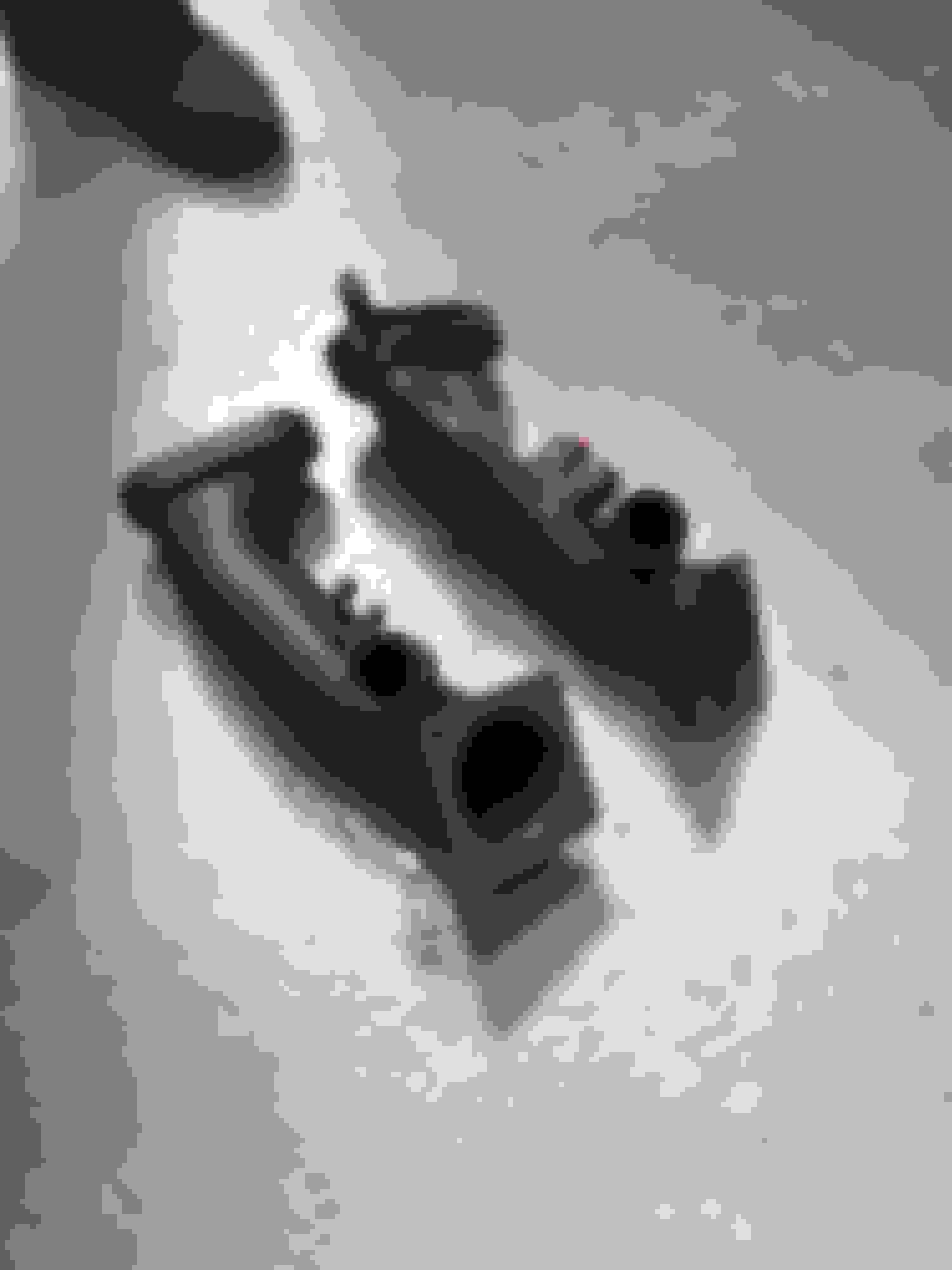
Below you can see side by side photos of my charge pipe and the OEM Unit.
On 2/9/2020 John, went to 1320 MINI.
The vehicle was loaded on the dyno with the OEM charge pipe. Result 233.9 whp and 186.2wtq. OK so that's our base line. (I have to say John has a really really fast MINI)
Off the dyno and the installation of my charge pipe started.
Charge pipe in !
And another side by side view.
And with that � back on the dyno!!
First three runs was with the same tune and only difference the TPE Precision charge pipe, resulting in 237.3 whp and 187.6 wtq.
Below the dyno run. But....
the 1320 MINI team saw that the AFR value was off (that's what I did not take into account into my own testing....) , thus more power was on the table.
After tuning, the car made 240.5 whp and 189.4 wtq!!!
Of course numbers along are half the truth, as the car gained whp and wtq in the whole RPM range!! And yes you can feel the difference on the road!
Additionally to the above we saw reduction in IATs from 3 to 5 degrees and increased boost pressure of up to 1 psi.
I have a detailed blog post into my website (yeap i did that as well ) but I am not going to upload it here as I do not want to be considered an advertisement.
I spoke many times with the owner of the car and he is extremely happy with the results and the way the car feels. John drives his car everyday and does many trackdays every year so I respect his opinion a lot.
What do you think?
Do you like it so far ? Comments and suggestions are more than welcome !
Have a nice day,
George .
I don't have an engineering degree nor really have a dog in this fight since I have the TVS900 now but I have a question on design for you.
1. Could you make this dbl walled with a honey comb between the two? If you did this could do this could the cavity between the two be filled with a gel or liquid that absorbs heat from the motor? (Would have to be very stout)
If you are not following what I am thinking I understand. The idea is based off of the Guage mounts that go into the vents how there is a inner and outer solid with a honeycomb in the middle.


 This time I dyno my own car, first time with the printed charge pipe and second time with the oem setup. The intake was exactly the same both times ( filter, air box, air tubes), everything was OEM (only difference was thecharge pipe). I did in total 4 runs each time. 100 RON fuel, close hood same temperature (26 degrees).
 (that's the easiest to conclude). It seems that with the printed model the engine responded a bit better, lower IATs and maybe it breaths a bit better.
 So defiantly this material is up to the task and so useful for testing.
  Should I designed a cheap airbox utilizing layser cut sheet metal and printed parts, with more volume ? Dyno again the car with OEM charge pipe plus the new airbox and then another dyno with the printed charge pipe plus the new air box. Compare all the data and decide ?