When you click on links to various merchants on this site and make a purchase, this can result in this site earning a commission. Affiliate programs and affiliations include, but are not limited to, the eBay Partner Network.
I think what I wrote above was a bit confusing! I meant that first I want to finish with all the details of the charge pipe and then start another project. But yes what you said it's true, first finish all the testing-dyno and all the finishing touches! I will up date the thread with any new details
I think what I wrote above was a bit confusing! I meant that first I want to finish with all the details of the charge pipe and then start another project. But yes what you said it's true, first finish all the testing-dyno and all the finishing touches! I will up date the thread with any new details
Thought I got to excited to quickly... Sticking around for the updates and results. Good stuff
Still watching, still waiting..!
Nice assembly fixturing by the way.
I'm retired and getting older every minute, please don't take too long to get this done...I may not be around to put in into my car..!
Still watching, still waiting..!
Nice assembly fixturing by the way.
I'm retired and getting older every minute, please don't take too long to get this done...I may not be around to put in into my car..!
Mike
Call me George please !!
I am a bit out of schedule I know a bit more I hope !
Thank you very much ! For now the test mule it's my car, as I want everything to be perfect before even trying into another test mule
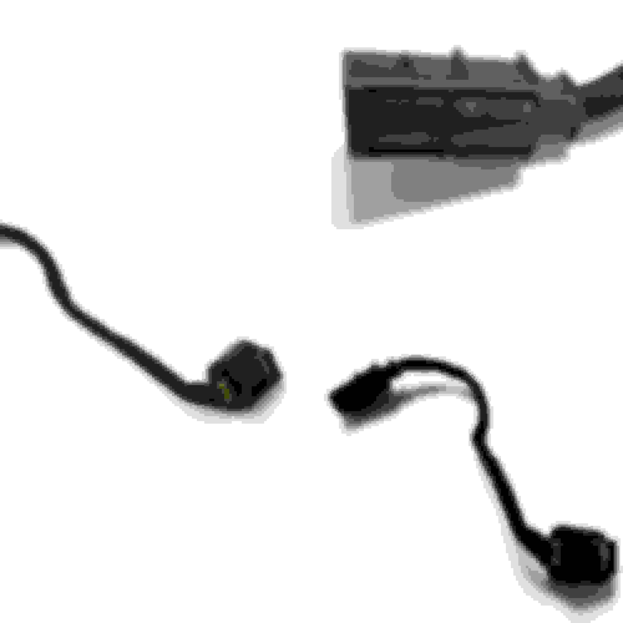
Below you can see the throttle cable extension that I have currently on my car:
And all the components that I need, in order to make more ,arrived today I would like to point out that everything you see is an original BMW component
Previously I mentioned (I think) that I did a MAP adapter� So I figure out it will be nice to explain the reasons why I did that.
Why do I need a MAP adapter?
Of course I could do it without it but�
The OEM plastic adapter after all these years of use can break pretty easily�. Ask me how I know !!
I think by now I made it clear that I want the charge pipe to be as plug n play as possible. So sometimes I might go over the top with small details (that�s one reason why I am sooo late)
So let me explain my thinking:
The OEM design comes with plastic vacuum lines that are connected to the MPA adapter. The problem arise when you want to remove the line from the adapter. Then you realize that you need to make a small cut in order to free the line from the OEM adaptor!! Let�s add that the OEM plastic map adapter breaks so easily �.and I am starting thinking that this is not so plug and play after all !! Additionally if I have to destroy the OEM lines, later I would not be able to use them again if for whatever reason I need to go back to the OEM setup (why? Ok I don�t know!! )
So I replaced the plastic vacuum lines with high pressure fuel lines (overkill, but I prefer to be safe than sorry ! ) And� I designed a map adapter exactly like the OEM unit. Then print the adapter by using NYLON 6.
Printed? But why ? how ?
Let me explain:
Nylon 6 is a polyamide plastic. It is widely used in engineering and especially in automotive industry and it has a broad range of properties ..
Some of them are:
oil and solvent resistance, fatigue, abrasion resistance, low friction, creep resistance, high tensile strength, thermal stability, fire resistance and drawability
So it is a really nice material to work with and especially for this application.
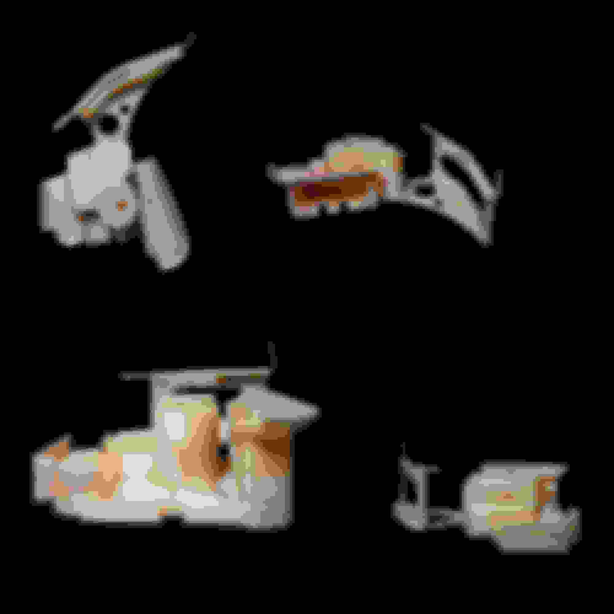
Below in the photo you can see the cad model as a whole, in section view, the real nylon 6 model and the full assembly with the MAP adapter on.
So what do you think? Overkill? You like it , you dont like it ?
And a small extra ....
This is the bypass take off....as it came out of the mold Yeap even that comes from a mold, everything is custom in this project. I am sure many of you will have questions now .... The bypass take off and the vacuum take off are attached to the main body . Why? Because only then you really have a truly unrestricted flow inside the charge pipe.... Slowly I will explain all the details of the project.
I hope you enjoyed this long (maybe boring ) post !!
So today I would like to discuss a bit about fitment
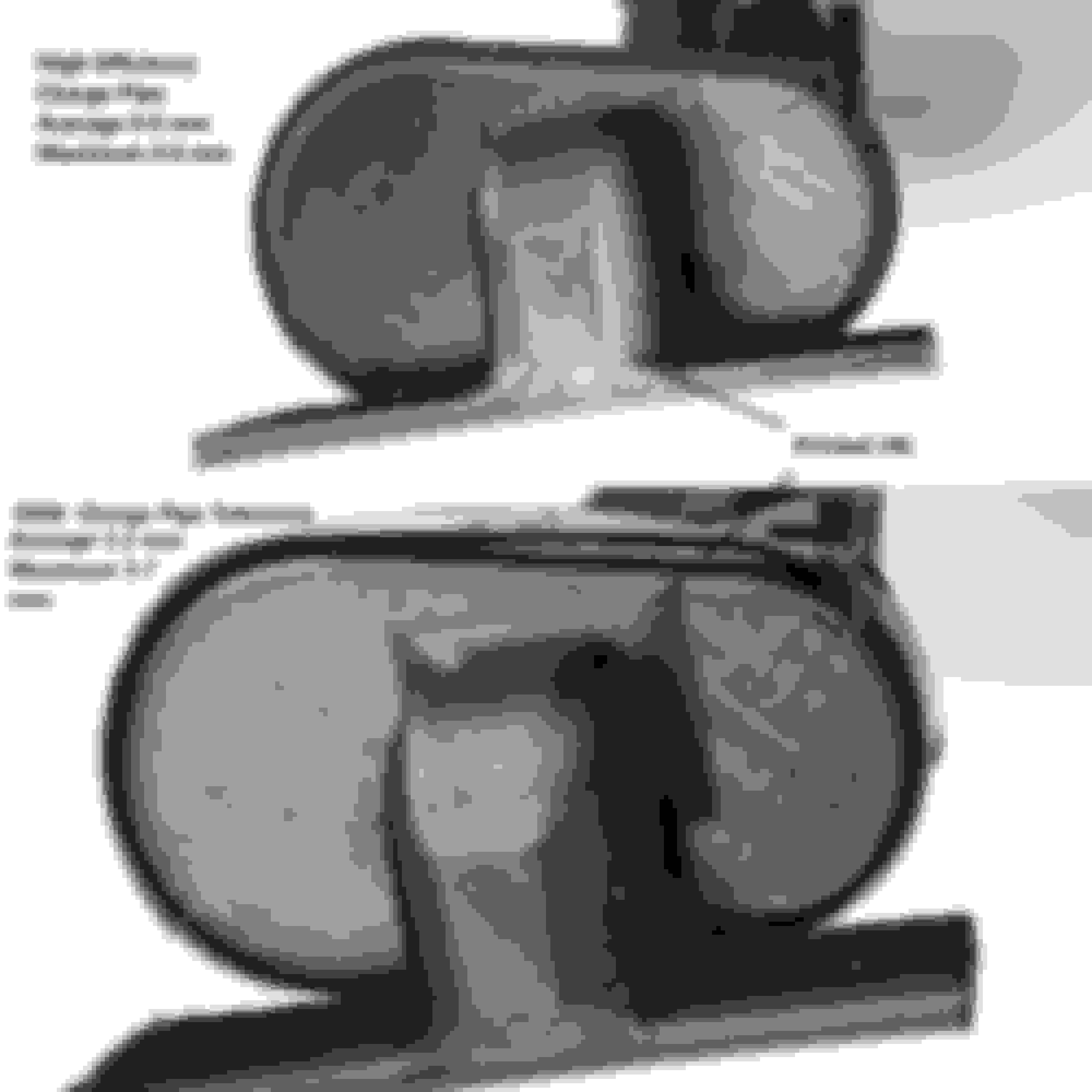
Increase tolerance and manufacturing processes are reasons for boost leaks in the OEM charge pipe design. One of the main problems is the way the OEM charge pipe seals with the green plastic gasket and the supercharger inlet. It seems like the tolerance between the gasket and the OEM charge pipe is a bit to much. That was one of the first things I wanted to address when I started designing.
Why tolerance matters?
Tolerance is the size between functional limits, the variation of a dimension’s value and the limit that controls the gap in an assembly.
What are the advantages of a low tolerance value in the charge pipe?
1. Most importantly elimination of boost leaks.
2. A fitment that allowed the whole charge pipe assembly to operate perfectly even without support ….for more than 5000 km under hard accelerations, highway and city driving. (I drove the car initially like that, before designing the supports. Now everything is shorted out of-course and the assembly utilizes two supports-brackets )
Below in the photo you can see the jig support the printed charge pipe and the OEM unit. Just check that gap of the OEM unit ! So what I did different ?
Instead of reverse engineering the OEM charge pipe flange, the green elastic flange was used as reference for the charge pipe’s outlet. That way a perfect fit was ensured (and extremely tight of-course)
I didn't look at your plots too closely but one thing you can do to help improve data is to to normalize it.
I would work in terms of pressure recovery. A differential pressure transducer with one tap mounted in a free air and the other mounted at the end of the supercharger would let you do that. Since the measurement at the inlet to the supercharge is being referenced to the atmosphere you will get more consistent data and automatically account for changes in barometric pressure and other small items.
Also be careful not to confuse the issue by call the inlet tube a boost tube. I'm sure you know it really only sees vacuum. So no issues with boost leaks from poor fitment. More likely you will have issues with vacuum leaks (which cause all sorts of other issues).
If you need help with data logging, pressure transducer selection, or analysis let me know. It's my day job. I was actually talking about a project like this with a friend at one point. We wanted to keep the stock TB location to reduce cost/effort. I love all the manufacturing techniques you are using.
You are correct ! It's not boost leak but vacuum.
When the time comes for more logging I will tell you.
Heat Shield's JIG design finally ready ! The main (big) part hasnt finish yet , the two extra pieces are ready (you can see them below).
For material I chose NYLON 6 as it is perfect for constructions like this one. I hope everything to go according plan so there will be no need to go back to the design board !
Thank you ! Both the heat shield and the charge pipe are carbon fiber.
How did the direct pipe work out?
You mean the charge pipe I guess. So far all good. For now I have only one actually working (in my car). Most of the small details are done. Next step is a fully prototype with the heat shield so I can at last do some dyno pulls and see the results !
Very interesting read and the product looks great. Waiting to see results from the dyno of stock vs new charge pipe. Would love to have this piece on my mini.
Very interesting read and the product looks great. Waiting to see results from the dyno of stock vs new charge pipe. Would love to have this piece on my mini.
There are MANY things that may or may not actually show up as good (OR bad) on a dyno, that actually do increase drive-ability, and maybe even the power curve in a area or two.
I'm on the list for one, I just hope I'm still breathing and can work on my own car (kidding !)..!
Thank you guys for the kind words. Dyno is one measurement but as said not the only one. What suprised me was that during the extreme hot Greek weather with the aircon on and without heatshield the car felt amazing. I was using it everyday to go to work, doing on a average 75km per day, with 38 to 40 degrees outside temp, traffic jams or open road. I even did hard pulls from 0km up to 200km with aircon on. Before with the aircon on and that heat my car was feeling ....lets say unhappy ! 😅
When the final product is out, more testing and data logging will help us understand!
I understand there is more to it than just dyno numbers. Most folks will be okay spending the money if it increases power. They dont usually spend money on modifications to improve gas mileage, its always more power. Its nice to see that the IAT temps are lower than with stock which is great. Id be fine with getting one at this point even with out the heat shield.


 a bit more I hope !

 I would like to point out that everything you see is an original BMW component