
Drivetrain Project "Low IAT"-Intake Manifold Cooling


Joined: Mar 2005
Posts: 3,989
Likes: 1
From: Westerly, RI
It is as Partsman says & the location is correct, however IATs that it displays on a scan are not actual temps. I looked at these temps with some medical equipment last July. It could be that the temps are an average over some period of time?????
Hey Partsman what do you think? Also the fiberglass paper is a great idea ( not to mention the cost ). I like it.....
Hey Partsman what do you think? Also the fiberglass paper is a great idea ( not to mention the cost ). I like it.....
As far as the temps being an average over a period of time, I really don't think that's the case, as I can watch them in real time with my ScanGaugeII. They go up as they normally would under boost, and then come down(rather quickly) after getting off the boost under normal cruise, and then stabilize. If they are being averaged over a period of time, it's a very short period.

6th Gear
Joined: Mar 2006
Posts: 1,710
Likes: 1
From: Northampton MA
Thanks Steve, the price for the fiberglass paper is definitely right, and I think it would work well.
As far as the temps being an average over a period of time, I really don't think that's the case, as I can watch them in real time with my ScanGaugeII. They go up as they normally would under boost, and then come down(rather quickly) after getting off the boost under normal cruise, and then stabilize. If they are being averaged over a period of time, it's a very short period.
As far as the temps being an average over a period of time, I really don't think that's the case, as I can watch them in real time with my ScanGaugeII. They go up as they normally would under boost, and then come down(rather quickly) after getting off the boost under normal cruise, and then stabilize. If they are being averaged over a period of time, it's a very short period.
It's too bad the paper is white. You may be able to use some Krylon plastic paint for a more suitable finish. On the plus side, that stuff is great. Went to the local heating & plumbing to see if they had it. Yup. You found another good, available mod for low $$$. Gotta love it

Joined: Mar 2005
Posts: 3,989
Likes: 1
From: Westerly, RI
This is true the temps do go up & down in real time & quite quickly. The med equipment, all ER stuff, showed much larger shifts in temp at the IC exit than the ScanII which makes me wonder how & what the sensor reads via the OS. The temps eventualy, over several minutes ( 2-5 ), even out at cruise so maybe I'm just getting too fussy. Rcovery time, IC wise, is very quick with an OE unit, quicker than anything that has been on this car but average temps are higher given the type of driving I do, especialy in town. The ScanII would say otherwise. Most of this data is moot with this exception, the recovery of the OE IC v bigger IC. It's hard to beat mass.
Originally Posted by stevecars60
It's too bad the paper is white. You may be able to use some Krylon plastic paint for a more suitable finish. On the plus side, that stuff is great. Went to the local heating & plumbing to see if they had it. Yup. You found another good, available mod for low $$$. Gotta love it
6th Gear
Joined: Mar 2006
Posts: 1,710
Likes: 1
From: Northampton MA
http://gasketsinc.thomasnet.com/item.../g-i-92?&seo=1 This is the material that I can get. Is this right? There is enough call for this with the "green" developers that it's usualy in stock. The link is their supplier.
Joined: Mar 2005
Posts: 3,989
Likes: 1
From: Westerly, RI
This is true the temps do go up & down in real time & quite quickly. The med equipment, all ER stuff, showed much larger shifts in temp at the IC exit than the ScanII which makes me wonder how & what the sensor reads via the OS. The temps eventualy, over several minutes ( 2-5 ), even out at cruise so maybe I'm just getting too fussy. Rcovery time, IC wise, is very quick with an OE unit, quicker than anything that has been on this car but average temps are higher given the type of driving I do, especialy in town. The ScanII would say otherwise. Most of this data is moot with this exception, the recovery of the OE IC v bigger IC. It's hard to beat mass.
I agree that nothing beats the stock IC in terms of recovery, and it's also quite efficient despite it's placement. I'm going to get my azz in gear to finish my direct flow stock unit, i'm very curious to see how it performs.
http://gasketsinc.thomasnet.com/item.../g-i-92?&seo=1 This is the material that I can get. Is this right? There is enough call for this with the "green" developers that it's usualy in stock. The link is their supplier.


6th Gear
Joined: Sep 2002
Posts: 2,196
Likes: 0
From: Hampton, VA
Is anything ever easy on this car?
Where the SC outlet horn wraps around the manifold is very tight, i'm going to try and find something to fit in between there to help keep the heat off that end of the manifold.
How sweet would a molded plastic(phenolic?) intake manifold be?
I think this is the bit I have in my Dremel...

http://www.dremel.com/en-us/attachme...=66357&I=66360
I pretty much just followed the flat of the shroud with it, I still need to smooth it up a little.
Where the SC outlet horn wraps around the manifold is very tight, i'm going to try and find something to fit in between there to help keep the heat off that end of the manifold.
How sweet would a molded plastic(phenolic?) intake manifold be?
I think this is the bit I have in my Dremel...
http://www.dremel.com/en-us/attachme...=66357&I=66360
I pretty much just followed the flat of the shroud with it, I still need to smooth it up a little.
That is a side cutting bit. If you wrap tape(heat shrink tubing) around most of it and just leave a usable section in the middle(or wherever works best) it won't mar surfaces you don't intend to.
Clean cut, minimal scratches.

Joined: Mar 2005
Posts: 3,989
Likes: 1
From: Westerly, RI
Nice job, El. I'm looking forward to seeing your version of the IMD.
Last edited by Partsman; May 20, 2007 at 02:54 PM.

3rd Gear
Joined: Dec 2003
Posts: 190
Likes: 0

My little dose of LITHIUM
iTrader: (1)
Joined: Jul 2005
Posts: 2,435
Likes: 2
From: Albuquerque New Mexico
Update on Aerogel:
I installed it with aerogel (black fabric) under the entire manifold, but the "touching" part -- which was silly micrometers gap, not actually touching -- is only one layer, elsewhere is 3 layers (reflective fabric, felt-like insulating core which is 2mm thick at least, and aerogel impregnated fabric.)

cheers,
I installed it with aerogel (black fabric) under the entire manifold, but the "touching" part -- which was silly micrometers gap, not actually touching -- is only one layer, elsewhere is 3 layers (reflective fabric, felt-like insulating core which is 2mm thick at least, and aerogel impregnated fabric.)
cheers,
Joined: Mar 2005
Posts: 3,989
Likes: 1
From: Westerly, RI
Update on Aerogel:
I installed it with aerogel (black fabric) under the entire manifold, but the "touching" part -- which was silly micrometers gap, not actually touching -- is only one layer, elsewhere is 3 layers (reflective fabric, felt-like insulating core which is 2mm thick at least, and aerogel impregnated fabric.)
cheers,
My little dose of LITHIUM
iTrader: (1)
Joined: Jul 2005
Posts: 2,435
Likes: 2
From: Albuquerque New Mexico
No problems from the hard grey line from the SC at all. No additional information to be had from showing you another photo, Joaquin. It's pretty much done by feel, not visually. I just slipped the blanket under the manifold and then held it down with my diverter. I sewed the blanket around the edge so that it's all one piece again, just a different shape.
Joined: Mar 2005
Posts: 3,989
Likes: 1
From: Westerly, RI
No problems from the hard grey line from the SC at all. No additional information to be had from showing you another photo, Joaquin. It's pretty much done by feel, not visually. I just slipped the blanket under the manifold and then held it down with my diverter. I sewed the blanket around the edge so that it's all one piece again, just a different shape.
Let us know if you see any further reduction in your IATs.
Steady cruise today between 50-55mph, I had a 3 degree difference. Ambient was 60 degrees. I think my hood vents have something to do with that low number.
My little dose of LITHIUM
iTrader: (1)
Joined: Jul 2005
Posts: 2,435
Likes: 2
From: Albuquerque New Mexico
But, I did learn something, I think. I insulated the outside of my airbox some time ago and it seems to work, but recently I insulated (with Al faced fibercloth) the inside of the airbox. My conclusion, --- insulation on inside BAD
 while insulation on outside, GOOD
I observed +2F higher airbox temps with internal insulation than without. So today I removed all internal insulation and painted everything black that wasn't already. Time will tell.


Joined: Mar 2005
Posts: 3,989
Likes: 1
From: Westerly, RI
Ah, yes... I've never seen an approach of 3, or 4F, ever!! (Not that I wouldn't give a lot to see that!) I've been getting approaches of 7-8F and today it was hot on the freeway, 70mph, 3k+rpm and I had 11F approach.
But, I did learn something, I think. I insulated the outside of my airbox some time ago and it seems to work, but recently I insulated (with Al faced fibercloth) the inside of the airbox. My conclusion, --- insulation on inside BAD while insulation on outside, GOOD
I observed +2F higher airbox temps with internal insulation than without. So today I removed all internal insulation and painted everything black that wasn't already. Time will tell.
But, I did learn something, I think. I insulated the outside of my airbox some time ago and it seems to work, but recently I insulated (with Al faced fibercloth) the inside of the airbox. My conclusion, --- insulation on inside BAD
while insulation on outside, GOOD I observed +2F higher airbox temps with internal insulation than without. So today I removed all internal insulation and painted everything black that wasn't already. Time will tell.
As you told me before, approach of 20 degrees or less and we're doing pretty good. I'm just amazed that we are able to get it into the single digits.
I'll have a WI setup soon, Sid. More than likely not progressive to start with, but who knows when i'll be pickin' your brain for that setup too.
I can't wait to see the difference in the IATs under boost with the WI.
3rd Gear
Joined: Dec 2003
Posts: 190
Likes: 0
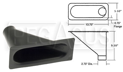
It is amazing what you guys are coming up with! Keep up the great work. I thought the following link might help you guys out. It has NACA and brake cooling ducts that could be used here. Let me know what you think.
Frodo
http://www.pegasusautoracing.com/adv...ryID=BRAKEDUCT
Frodo
http://www.pegasusautoracing.com/adv...ryID=BRAKEDUCT
Joined: Mar 2005
Posts: 3,989
Likes: 1
From: Westerly, RI
It is amazing what you guys are coming up with! Keep up the great work. I thought the following link might help you guys out. It has NACA and brake cooling ducts that could be used here. Let me know what you think.
Frodo
http://www.pegasusautoracing.com/adv...ryID=BRAKEDUCT
Frodo
http://www.pegasusautoracing.com/adv...ryID=BRAKEDUCT
I have been looking for something like this...
...for further experiments. Thanks again.
6th Gear
Joined: Sep 2002
Posts: 2,196
Likes: 0
From: Hampton, VA
Ah, yes... I've never seen an approach of 3, or 4F, ever!! (Not that I wouldn't give a lot to see that!) I've been getting approaches of 7-8F and today it was hot on the freeway, 70mph, 3k+rpm and I had 11F approach.
But, I did learn something, I think. I insulated the outside of my airbox some time ago and it seems to work, but recently I insulated (with Al faced fibercloth) the inside of the airbox. My conclusion, --- insulation on inside BAD while insulation on outside, GOOD
I observed +2F higher airbox temps with internal insulation than without. So today I removed all internal insulation and painted everything black that wasn't already. Time will tell.
But, I did learn something, I think. I insulated the outside of my airbox some time ago and it seems to work, but recently I insulated (with Al faced fibercloth) the inside of the airbox. My conclusion, --- insulation on inside BAD
while insulation on outside, GOOD I observed +2F higher airbox temps with internal insulation than without. So today I removed all internal insulation and painted everything black that wasn't already. Time will tell.
Bear in mind too that even a small incline, either positive or negative, can make a noticeable difference in readings.( Just a general comment not a reflection on your post
)Side note. I have insulated from the inside only on my HDI. All it really did is slow rise time for temps inside the box at idle.
same old mass vs thermal cycling speed thing.


I've been rather quiet lately and after having talked w/ Partsman, he got my juices flowing so I thought I would jump in to the thread.
I think he is on to something here as well as DocPhil with the placement of the aerogel between the SC and intake. I'm not sure if its necessary to remove the entire stock plastic shield perhaps just a duct pointing at the intake will get the job done. Of course, I am only able to say this now based on the numbers Partsman has generated with the entire stock platic piece removed.
One question - have radiator temps changed? Does this size opening take anything away from the radiator?
Second question - With all that air hitting the intake perhaps the addition of cooling fins to the intake might be in order?
One thing that we talked about was the foam strip between the radiator and the plastic shroud. Partsman shared that the plastic shroud goes down over the radiator creating a lip in the back. Perhaps removing the foam, dremeling off the plastic to create a see thru opening and adding a diverter to direct air upwards is worth considering? Partsman pointed out that while a small opening it runs the length of the shroud and is lower down and should grab air.
On a side note - Having dremel-mania experience, its a shame he did not video record his dremel action.

The fins aren't really going to do anyhing useful. To work effectively they need to dissipate more heat than the mass you are trying to cool( at least come close to breaking even). Those little fins on that hot azz intake are going to lose big time.
The entire bottom of the IC covered in them would be slightly more effective but what you'd really need is units so thin and light it'd be expensive. A single layer honeycomb matrix would work well also. Or start slicing and dicing those old stock IC you guys have lying around
Still not sure of the benefit though.
Joined: Mar 2005
Posts: 3,989
Likes: 1
From: Westerly, RI
I've been rather quiet lately and after having talked w/ Partsman, he got my juices flowing so I thought I would jump in to the thread.
I think he is on to something here as well as DocPhil with the placement of the aerogel between the SC and intake. I'm not sure if its necessary to remove the entire stock plastic shield perhaps just a duct pointing at the intake will get the job done. Of course, I am only able to say this now based on the numbers Partsman has generated with the entire stock platic piece removed.
I think he is on to something here as well as DocPhil with the placement of the aerogel between the SC and intake. I'm not sure if its necessary to remove the entire stock plastic shield perhaps just a duct pointing at the intake will get the job done. Of course, I am only able to say this now based on the numbers Partsman has generated with the entire stock platic piece removed.
The fact that DrPhil was able to fit his aerogel in between the SC and manifold with some minor modification is awesome. I'm still waiting to hear from him as to the temps he's seeing now.
Originally Posted by Bahamabart
One question - have radiator temps changed? Does this size opening take anything away from the radiator?
Second question - With all that air hitting the intake perhaps the addition of cooling fins to the intake might be in order?
Second question - With all that air hitting the intake perhaps the addition of cooling fins to the intake might be in order?
The cooling fins have been discussed in this thread(as well as others) and I think the verdict is still out on that setup.
Originally Posted by Bahamabart
One thing that we talked about was the foam strip between the radiator and the plastic shroud. Partsman shared that the plastic shroud goes down over the radiator creating a lip in the back. Perhaps removing the foam, dremeling off the plastic to create a see thru opening and adding a diverter to direct air upwards is worth considering? Partsman pointed out that while a small opening it runs the length of the shroud and is lower down and should grab air.

...the radiator hose would still be in the way, and pretty much heating the air being ducted to the manifold.
Originally Posted by Bahamabart
On a side note - Having dremel-mania experience, its a shame he did not video record his dremel action.
I'll have to remember the video camera next time I Dremel a chunk of my car off.
. The shavings = a chunk.
Your running out of plastic !
