
Drivetrain Project "Low IAT"-Intake Manifold Cooling


OVERDRIVE


Joined: May 2003
Posts: 7,926
Likes: 40
From: Greensboro, NC
Sid, or anyone else, what do these heat sinks cost, and are there some types better than others, or better for this application?
I think it will be hard to discern if this works on our MINI, with so many dynamics at play. I really hope we can get some proof with some simple, controlled testing, like what I provided in my previous post...
I think it will be hard to discern if this works on our MINI, with so many dynamics at play. I really hope we can get some proof with some simple, controlled testing, like what I provided in my previous post...

6th Gear
Joined: Mar 2006
Posts: 1,710
Likes: 1
From: Northampton MA
epoxy with silver shavings in it.
http://www.newegg.com/Product/Produc...82E16835100005
not sure how hot it can get before it melts... i've personally pushed it to 90 deg celcius on some parts of my motherboard and video card memory.

edit:
http://www.newegg.com/Product/Produc...82E16835100005
not sure how hot it can get before it melts... i've personally pushed it to 90 deg celcius on some parts of my motherboard and video card memory.
edit:
1 thing you need to know is the surface on both sides of the epoxy need to be matched as close as possible ( you don't want too much epoxy filling voids ). The aluminum version of JB weld isn't so fussy & does conduct pretty well but not anywhere near the Artic silver.
Hey Partsman that piece looks just like it should
For heat shielding http://www.heatshieldproducts.com/index.php

Joined: Mar 2005
Posts: 3,989
Likes: 1
From: Westerly, RI
Hey Partsman that piece looks just like it should
For heat shielding http://www.heatshieldproducts.com/index.php
For heat shielding http://www.heatshieldproducts.com/index.php
Thanks for the link.
My little dose of LITHIUM
iTrader: (1)
Joined: Jul 2005
Posts: 2,435
Likes: 2
From: Albuquerque New Mexico
Latest news
Here are some more photos to help people understand what we're doing, and what variations are arising.
Here's what mine looks like today:

For those who would like an idea of what has been removed, I placed the gasket back in its original position:

and what does all this do (remember I am running a lot more than the IMD (Alta CAI, Gandini FAD, OEM ram duct to airbox with new tube, DFIC, IC foils, RBH-FAD scoop--which all contribute to the IATs).

Geez, I just noticed that 75-68=7--duh. Oh well you get the idea...
Just cruising on the freeway in morning commute traffic, after about 3 minutes building up to 70mph. Single digit approach
Here's what mine looks like today:
For those who would like an idea of what has been removed, I placed the gasket back in its original position:
and what does all this do (remember I am running a lot more than the IMD (Alta CAI, Gandini FAD, OEM ram duct to airbox with new tube, DFIC, IC foils, RBH-FAD scoop--which all contribute to the IATs).
Geez, I just noticed that 75-68=7--duh. Oh well you get the idea...
Just cruising on the freeway in morning commute traffic, after about 3 minutes building up to 70mph. Single digit approach
Last edited by DrPhilGandini; May 17, 2007 at 08:37 AM.

ok clearly there is some air to be had up there. I mean that shrowd wouldn't be there if there weren't. But, I'm having a hard time wrapping my brain around a few things. Your data points suggest that air is moving. However, after looking at the pics of the m7 cosworth car, how is a significant amount of air going to make it's way up a few inches after clearing the grill, over the home made diverters and across the manifold.
I'm bringing this up because I'm starting to think it isn't the air moving across the manifold that is cooling it but rather removing the stagnant air that sits between the back of the radiator and the between the supercharger.
It's a moot point I guess... Moving air is moving air. I just wonder what is the true path of least resistance and does air actualy make the jump up a few inches after the grill to end up in across the manifold or does it just go through the radiator and float up once warmed?
sorry for the rambling.

6th Gear
Joined: Sep 2002
Posts: 2,196
Likes: 0
From: Hampton, VA
Since I'm waaaay too lazy to read this whole thread right now I'll repeat some(from memory) findings I posted here quite a few months back.
In a nutshell this is a bad idea in conjunction with the stock IC.
What you in essence do is create a high pressure area under the stock IC that prevents good flow through the IC.
TBH there is a MUCH eaasier way to test this. Simply remove the gasket and build a flow tunnel to that area. Given that my flow input would be less than what would be developed by what I see here I can only guess, yes guess, that the negative impact of doing thiswith a stock IC would be even greater. You will just shear off decent flow though the IC.
this is my thought as well and why i have been asking so many questions. thanks for comming out and voicing it instead of beating around the bush like i have been.
My little dose of LITHIUM
iTrader: (1)
Joined: Jul 2005
Posts: 2,435
Likes: 2
From: Albuquerque New Mexico
Absolutely, obehave! I recall contributing to those earlier threads and have never disagreed with you concerning the airflow in/through/around the DFIC compared to the DDIC (down draft including stock IC).
If someone with a stock IC wants to do this, and take measurements, then we'll certainly answer the question...!
For me, this is a no-brainer. After 4 days I have yet to see any (can I repeat...any) detrimental impact on water temperatures (I can't measure oil temps) while enjoying significant reductions in IATs.
I also thought of another reason why MINI put that shroud and gasket there OEM (since the question has been raised as to the original intent.) It could conceivably be to reduce water ingress from the grille to the engine bay. There is considerable evidence that all modern car manufacturers do a lot to prevent water entering the engine bay. Also, even though *we* all know that a little water doesn't do bad things to engines, that's not relevant to manufacturers who have to deal with thousands of customers willing to blame all sorts of problems on water getting on the spark plug leads or in the air filter, etc.
and btw, obehave, if you had read the whole thread, I think you'll find that the only people who have actually cut the shroud and posted photos of it have DFICs. Which is a good thing...
Last edited by DrPhilGandini; May 16, 2007 at 10:36 AM.
6th Gear
Joined: Mar 2006
Posts: 1,710
Likes: 1
From: Northampton MA
Radiator shroud
Some pics. Not too good but all the time I had was less than 1 hour......
The top of the shroud would need some moding for ducting air to where it needs to go. Like a a pair of bends to collect air below the top of the grill.
I believe Obe is right about the stock IC. However if air is diverted away fron the IC, to the intake, with a second fence.......... Maybe. Need to go there & see. By the way Obe haven't seen you around much. Glad you stoped by.......

6th Gear
Joined: Feb 2007
Posts: 1,542
Likes: 0
From: Central Texas
epoxy with silver shavings in it.
http://www.newegg.com/Product/Produc...82E16835100005
not sure how hot it can get before it melts... i've personally pushed it to 90 deg celcius on some parts of my motherboard and video card memory.
edit:
http://www.newegg.com/Product/Produc...82E16835100005
not sure how hot it can get before it melts... i've personally pushed it to 90 deg celcius on some parts of my motherboard and video card memory.
edit:
Temperature range:
- 40C to >150C (Bond strength is weakened at temperatures
below 0C due to crystallization.)
My little dose of LITHIUM
iTrader: (1)
Joined: Jul 2005
Posts: 2,435
Likes: 2
From: Albuquerque New Mexico
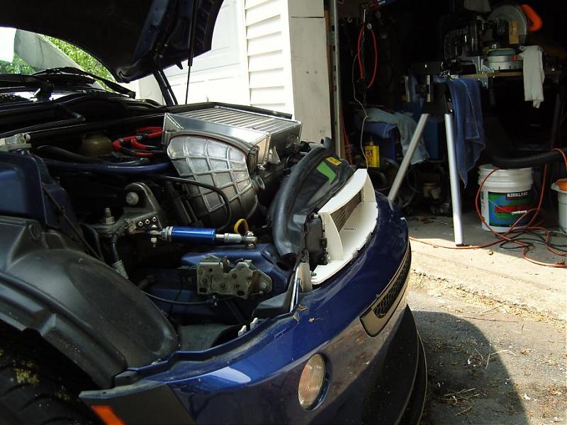
 That bonnet looks kinda see through...
 Wow--I would not have thought that there was that much room behind the bonnet/grille, but the proofs in the pudding, as they say. The top section reveals how much space there is for air to move up to the IMD. I will fab some side panels for sure. Can you give dimensions, especially stand off at the top, and bottom, of the side panels?
cheers,
Joined: Mar 2005
Posts: 3,989
Likes: 1
From: Westerly, RI
I was thinking of something very similar to this, with a couple vertical diverters on top of the IMD.
A pair of bends on the end of the IMD would most definitely help the air to the manifold, i'm going to make another one that extends a little farther to the grille and bend it like the one now and try that first.
6th Gear
Joined: Sep 2002
Posts: 2,196
Likes: 0
From: Hampton, VA

If I can help but one person......

I went back and took a look at phil's. I didn't see the remaining parts of the shrowd until now. Cool stuff.
I've been thinking of toying with some of this stuff with my stock IC and hoodscoop. Mind if i shoot some pm's back and forth with you doc to see if getting measuring equipment could be a reality for me?
I've been thinking of toying with some of this stuff with my stock IC and hoodscoop. Mind if i shoot some pm's back and forth with you doc to see if getting measuring equipment could be a reality for me?
This looks like a nice idea for the DFIC folks but I'm thinking maybe not for the stock IC people.
The fins aren't really going to do anyhing useful. To work effectively they need to dissipate more heat than the mass you are trying to cool( at least come close to breaking even). Those little fins on that hot azz intake are going to lose big time.
The entire bottom of the IC covered in them would be slightly more effective but what you'd really need is units so thin and light it'd be expensive. A single layer honeycomb matrix would work well also. Or start slicing and dicing those old stock IC you guys have lying around

Still not sure of the benefit though.
You want to make the conducting gel more effective? Gather up a cup of fine aluminum filings and mix them in before applying. Some of the industrial gels/adhesives are exactly that, powdered Al mixtures.
Joined: Mar 2005
Posts: 3,989
Likes: 1
From: Westerly, RI
Since I'm waaaay too lazy to read this whole thread right now I'll repeat some(from memory) findings I posted here quite a few months back.
In a nutshell this is a bad idea in conjunction with the stock IC.
What you in essence do is create a high pressure area under the stock IC that prevents good flow through the IC.
TBH there is a MUCH eaasier way to test this. Simply remove the gasket and build a flow tunnel to that area. Given that my flow input would be less than what would be developed by what I see here I can only guess, yes guess, that the negative impact of doing thiswith a stock IC would be even greater. You will just shear off decent flow though the IC.
In a nutshell this is a bad idea in conjunction with the stock IC.
What you in essence do is create a high pressure area under the stock IC that prevents good flow through the IC.
TBH there is a MUCH eaasier way to test this. Simply remove the gasket and build a flow tunnel to that area. Given that my flow input would be less than what would be developed by what I see here I can only guess, yes guess, that the negative impact of doing thiswith a stock IC would be even greater. You will just shear off decent flow though the IC.
As DrPhil said, the only guys that have the mod have a DFIC. For the guys running the stock IC, what if you seal off the area in front of the IC right above the manifold so none of the IMD air gets underneath, but still hits the manifold?
6th Gear
Joined: Sep 2002
Posts: 2,196
Likes: 0
From: Hampton, VA
Some pics. Not too good but all the time I had was less than 1 hour......
The top of the shroud would need some moding for ducting air to where it needs to go. Like a a pair of bends to collect air below the top of the grill.
I believe Obe is right about the stock IC. However if air is diverted away fron the IC, to the intake, with a second fence.......... Maybe. Need to go there & see. By the way Obe haven't seen you around much. Glad you stoped by.......
The top of the shroud would need some moding for ducting air to where it needs to go. Like a a pair of bends to collect air below the top of the grill.
I believe Obe is right about the stock IC. However if air is diverted away fron the IC, to the intake, with a second fence.......... Maybe. Need to go there & see. By the way Obe haven't seen you around much. Glad you stoped by.......
Very nice, very clean. Just coat it with resin, paint it and you're good.
Yes...I've been.. "away"

Life got in the way for a bit and then I was out of the habit of popping in.
My little dose of LITHIUM
iTrader: (1)
Joined: Jul 2005
Posts: 2,435
Likes: 2
From: Albuquerque New Mexico
I think Dr Obnxs also said this also on a couple of different threads. As I said sometime back there on page 2...it's a question of heat dissipation v. thermal mass. We're polishing turds here, and the effort/cost to put fins on the manifold may not be worth it especially if it increases the thermal mass more than it increases heat dissipation...
6th Gear
Joined: Mar 2006
Posts: 1,710
Likes: 1
From: Northampton MA
"There is considerable evidence that all modern car manufacturers do a lot to prevent water entering the engine bay. Also, even though *we* all know that a little water doesn't do bad things to engines, that's not relevant to manufacturers who have to deal with thousands of customers willing to blame all sorts of problems on water getting on the spark plug leads or in the air filter, etc."
When it is very hot where you are I'd be interested in what your water temp is. To reduce size & weight radiators are smaller & lighter so getting enough air to them is a big issue, especialy with an air conditioner rad mounted in front of the water ( those suckers get real hot ). Water & other debris are a concern but getting enough air to the radiator is 90% why the the shroud is sealed. Just the little piece of foam between the radiator & the shroud is a tell. This is the reason I made a model to look at.
The model extends right to the grill - leaves the foam ( between the radiator & shroud ). As pictured it will not help with your mission, it needs to collect air from the top of the grill for the DFIC ( the mock up, top, blocks off the air that you are adding ). Without the top piece the 2 fences may be enough to provide enough air for the radiator but I think not.
At 1 point last Aug I removed the shroud seal & just about every other air routing device & found that "in motion" temps were, in fact, lower. In slow moving traffic the recovery was way slow, much slower than with the shroud seal ( this was the 1 piece that made a big difference ).
thanks for the info obehave. I'm a computer throw back and now since ive converted to water and promethia cooling on all my rigs I've got alot of very thin fin copper heatsinks around to play with... here's an example of one I have 4 of and nothing to do with.
http://www.overclockers.com/articles959/
Sorry I don't want to hotlink pics to this site... I used to moderate on their forums and don't want to bandwidth destroy their site.
I'm gonna use these some how or give them away to some mini bud's for experiments.
Please return to your regularly scheduled modding discussion... thanks again for the info guys. Sorry I don't have more to add.


6th Gear
Joined: Apr 2003
Posts: 3,957
Likes: 2
From: a canyon, south Bay Area
Phil, nice work, and numbers!
6th Gear
Joined: Mar 2006
Posts: 1,710
Likes: 1
From: Northampton MA
Partsman, The secret's out of the bag. Foam core. Thanks Obe. Most pieces that get fabed are foam core for a rough measurement then MDF for a production aluminum piece.
Dr Phil, yes there is room behind the grill. The end plates actualy touch the devider on the grill where the holes are blocked off ( you could use some 1/8" weather seal for a little more air ). Realy, I'm concerned about the cut shroud. When time permits I'll make a pattern. The mock up needs quite a bit of tweaking, like there is not enough material to atach to the shroud mount, seal off the bottom of the radiator, look boss......
I may build 1 of these for this car just to see if the system recovery is faster. Bottom line, I will build a proto & patern.
6th Gear
Joined: Sep 2002
Posts: 2,196
Likes: 0
From: Hampton, VA
thanks for the info obehave. I'm a computer throw back and now since ive converted to water and promethia cooling on all my rigs I've got alot of very thin fin copper heatsinks around to play with... here's an example of one I have 4 of and nothing to do with.
http://www.overclockers.com/articles959/
Sorry I don't want to hotlink pics to this site... I used to moderate on their forums and don't want to bandwidth destroy their site.
I'm gonna use these some how or give them away to some mini bud's for experiments.
Please return to your regularly scheduled modding discussion... thanks again for the info guys. Sorry I don't have more to add.
http://www.overclockers.com/articles959/
Sorry I don't want to hotlink pics to this site... I used to moderate on their forums and don't want to bandwidth destroy their site.
I'm gonna use these some how or give them away to some mini bud's for experiments.
Please return to your regularly scheduled modding discussion... thanks again for the info guys. Sorry I don't have more to add.
6th Gear
Joined: Mar 2006
Posts: 1,710
Likes: 1
From: Northampton MA
This is something to look at, for many reasons. I have lots of foam core, more foam core than time. The next time I have time.... Remove the front bumper cover for a look.....
Joined: Mar 2005
Posts: 3,989
Likes: 1
From: Westerly, RI
I may have to bolt my stock IC back on to try it out.
