Mini Cooper 2001-2006: How to Replace Oxygen Sensor(s)
For utmost performance and engine efficiency, the oxygen sensors can be replaced at 50K mile intervals to prevent typical sensor aging and lazy response times. New O2 sensors will help ensure your engine is getting the proper fueling it needs for optimum operation.
This article applies to the Mini Cooper/Cooper S (2001-2006).
As with all modern fuel-injected engines, the Mini Cooper and Cooper S models use oxygen sensors (O2 sensors) to monitor the exhaust gases to determine engine combustion efficiency. The Mini uses 1 narrowband O2 sensor located in the exhaust manifold to constantly evaluate the level of oxygen in the exhaust to determine the air-fuel mixture. This sensor works in conjunction with the powertrain control module (PCM) to alter the fueling and bring the mixture to an ideal 14.7:1 ratio. The post catalyst O2 sensor monitors the function of the catalytic converter to ensure the exhaust exiting the vehicle meets emission standards.
Mini suggests replacing these sensors every 100K miles; however, most technicians agree that there is typically no need to replace them unless the vehicle has an O2 sensor related check engine light (CEL). In fact, a number of Mini owners have chalked up 250K+ miles on the odometer and the sensors are still going strong. In the event that the sensor(s) fails on your 2001-2006 Cooper or Cooper S, this article will outline the sensor replacement procedure to get your car back in tip-top shape.

Materials Needed
- Floor jack & jack stands
- 22mm wrench
- O2 sensor socket and ratchet
- Anti-seize paste
- New O2 sensor(s)
Step 1 – Upstream O2 sensor replacement
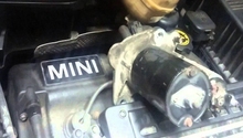
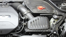
The upstream O2 sensor can be accessed from the top of the engine bay.
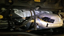
- Locate the upstream O2 sensor electrical harness plug. It is best found by looking down between the airbox and oil filler cap.
- Study the routing of the sensor wiring before sliding the wire out of the hold-down clips. Disconnect the sensor wiring plug.
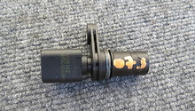
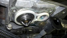
- Using a 22mm wrench or ratchet & O2 sensor socket, remove the O2 sensor from the exhaust manifold.
- Apply anti-seize paste to the threads of the new sensor before installing it into the manifold. Torque the sensor to approximately 30 ft/lbs.
- Secure the sensor wiring to the hold-down clips before reconnecting the wiring plug.
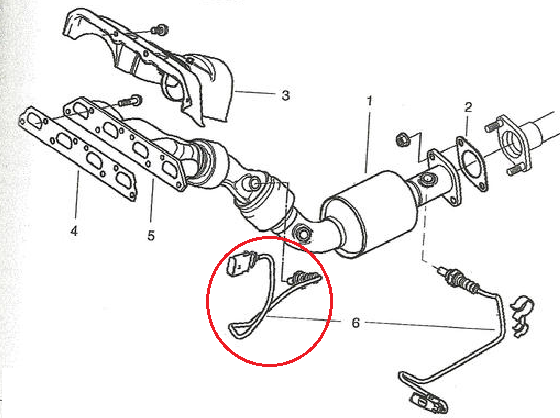

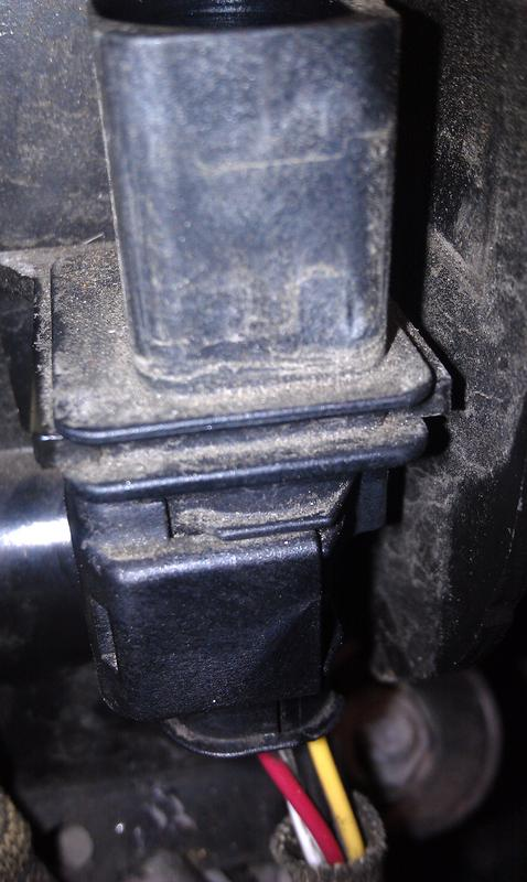
Figure 3. Closeup of O2 sensor wiring harness plug. 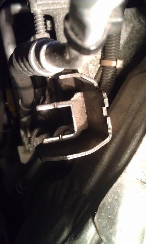
Figure 4. Closeup of O2 sensor plug hold-down.
Pro Tip
Applying penetrating oil to the threads of stubborn O2 sensors can break down rust and aid in removal.
Step 2 – Downstream (post-catalyst) O2 sensor replacement
The downstream O2 sensor is easily accessed from underneath the vehicle.
- Using a floor jack and jack stands, lift and support the vehicle at the factory specified lift points. Similarly, the car can be driven onto ramps in order to gain the necessary ground clearance for working underneath the vehicle.

Figure 5. Jack up your Mini. - On the left side (driver side) of the exhaust system, disconnect the O2 sensor wiring plug.
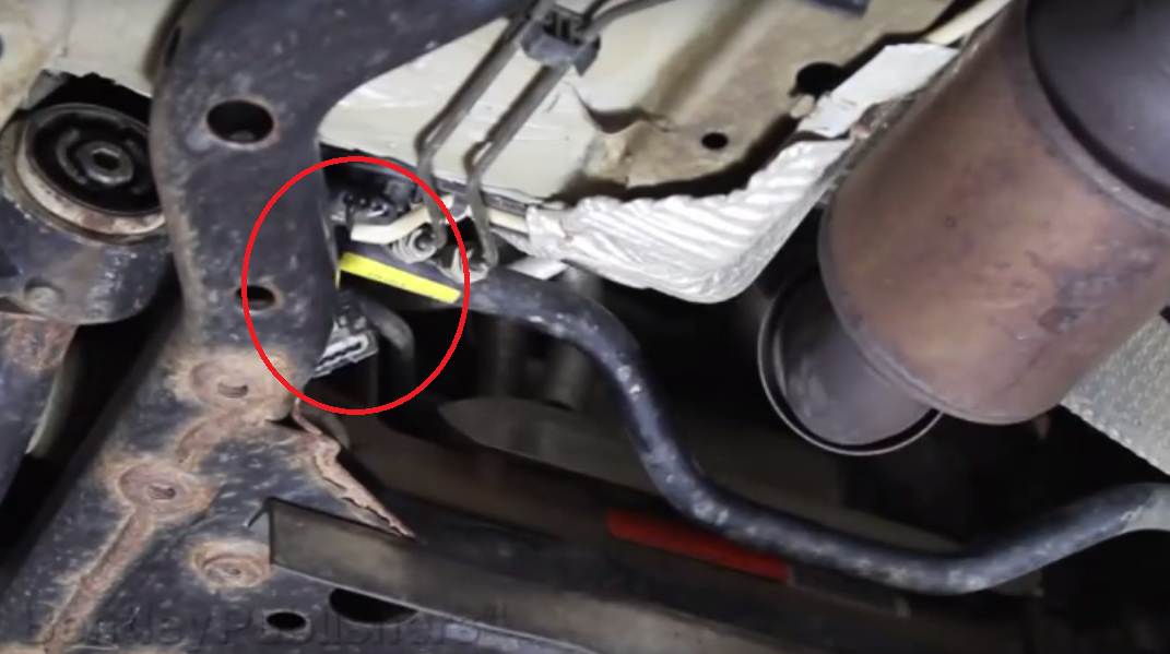
Figure 6. Post catalyst O2 sensor wiring harness. - Remove the heat shield fasteners and slightly bend the heat shield away from the body to access the concealed sensor wiring.
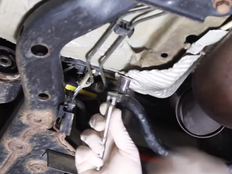
Figure 7. Heat shield hold-down fastener. - Free the wiring harness from the heat shield clips and route the harness through the brake lines until it hangs free.

Figure 8. Routing O2 sensor wiring through brake lines and heat shield clips. - Using a 22mm wrench or O2 sensor specialty socket & ratchet, remove the O2 sensor from the exhaust pipe.

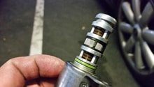
Figure 9. Removing O2 sensor from exhaust pipe. - Apply a small amount of anti-seize paste to the threads of the new O2 sensor before installing it into the exhaust pipe. Torque the sensor to approximately 30 ft/lbs.
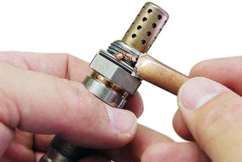
Figure 10. Anti-seize paste applied to threads. - Route the wiring along the heat shield and clip it into place. Route the plug through the brake lines before reconnecting the plug into the main wiring harness.

Figure 11. Routing wiring harness along heat shield clips. - Tighten the the heat shield back into place and install the heat shield fastener.

Figure 12. Securing heat shield in place. -
Lower the vehicle off of jack stands or ramps.
Pro Tip
It is important to properly route the O2 sensor wiring to prevent premature sensor failure related to frayed or pinched wiring.
Related Discussions
- Oxygen Sensor Replacement? - NorthAmericanMotoring.com
- DIY Oxygen Sensor Replacement? - NorthAmericanMotoring.com
- Nagging P0130 OBD Code - NorthAmericanMotoring.com