
Tigger 2.0

I would consider getting a better bracket for your Downpipe. I speak from experience from having the Riss Racing one. The engine moves too much and it will cause that bracket to sheer off.

Joined: Jul 2013
Posts: 1,474
Likes: 248
From: Sunrise, FL
Thanks for the tip. I'll keep an eye on it. I remember thinking when I got the WMW DP that the bracket looked a bit anemic compared to the factory one. But I liked how much thicker the flange was. Hopefully it doesn't give me any problems. Probably should have beefed it up before getting it ceramic coated.

Joined: Jul 2013
Posts: 1,474
Likes: 248
From: Sunrise, FL
I would think it would be less of a concern. When I had the custom exhaust installed I had an 8" flex pipe installed instead of a 6" to allow more flex in the exhaust where the DP attaches. I also have the yellow Powerflex engine mount. It's a little more flexible than the purple one but in an automatic you really don't want too rigid of a mount as it will transmit too much vibration when the car is in drive and you are stopped.

I love the motor mount in my GP2, but hated it in my friends built hybrid S automatic
__________________
2013 GP2 #295, 270whp/310wtq, KO4 47mm Turbo, 18" NM Wheels, Alta intake, Manic Stage III+, HFS-3 Meth, 30% E85 Blend, Forged IC, Alta Hot Pipe, P&P/Ceramic Exhaust Manifold, m3 Extreme Ceramic DP, Vibrant mid res, 4" Double walled Tips, WMW/KW V3 CO, Alta Rear CA, CREE Fogs, Black out F/R Rings and Gas Cap, M7 CF Front Splitter, and No Stickers. MORE TO COME!! Previous 04Triple Black 17% Alta, MM Air/H2O, CAI, OBX Header, FBT Head, Shrick Cam, 234whp
2013 GP2 #295, 270whp/310wtq, KO4 47mm Turbo, 18" NM Wheels, Alta intake, Manic Stage III+, HFS-3 Meth, 30% E85 Blend, Forged IC, Alta Hot Pipe, P&P/Ceramic Exhaust Manifold, m3 Extreme Ceramic DP, Vibrant mid res, 4" Double walled Tips, WMW/KW V3 CO, Alta Rear CA, CREE Fogs, Black out F/R Rings and Gas Cap, M7 CF Front Splitter, and No Stickers. MORE TO COME!! Previous 04Triple Black 17% Alta, MM Air/H2O, CAI, OBX Header, FBT Head, Shrick Cam, 234whp
Joined: Jul 2013
Posts: 1,474
Likes: 248
From: Sunrise, FL
More shiney stuff for salty
Since the engine is going to be out I figured I might as well change all the rubber coolant and boost hoses. Picked these up from Way Motor Works.

Coolant hoses.

Boost tubes.
Next up...turbo selection.
Coolant hoses.
Boost tubes.
Next up...turbo selection.


6th Gear
Joined: Feb 2007
Posts: 1,521
Likes: 17
I'm just reading along, but with a complete build like your doing I'd be upping the HP numbers you'll be happy to achieve... Plenty of 2nd Gen MINIs out there with 210-ish with just basic mods and a good tune.. Surely you'll end up with your hopes of 270. A good tune will be important to it all of course..
Joined: Jul 2013
Posts: 1,474
Likes: 248
From: Sunrise, FL
 ...but more about that later when we get to the tuning section.

IIRC you went with CP 10.5:1 pistons which are alloy 2168. What are the engine warm up recommendations when using this alloy? The reason I ask is that I was reading a different thread where someone posted to not even move the car until it the engine warmed up completely to 175F. Wow, this seems extreme. I understand that you want to be gentle until fully warm but to not actually move it? I mean for me, during the winter in NC this can take 30 minutes at idle and I park indoors.
On a side note, do you know if the stock JCW/GP2 pistons are alloy 4032?
On a side note, do you know if the stock JCW/GP2 pistons are alloy 4032?
Joined: Jul 2013
Posts: 1,474
Likes: 248
From: Sunrise, FL
IIRC you went with CP 10.5:1 pistons which are alloy 2168. What are the engine warm up recommendations when using this alloy? The reason I ask is that I was reading a different thread where someone posted to not even move the car until it the engine warmed up completely to 175F. Wow, this seems extreme.
Yep 4032. Well Mahle's variant of it anyway.
How do you always have such good info, even at 3:30am?
__________________
2013 GP2 #295, 270whp/310wtq, KO4 47mm Turbo, 18" NM Wheels, Alta intake, Manic Stage III+, HFS-3 Meth, 30% E85 Blend, Forged IC, Alta Hot Pipe, P&P/Ceramic Exhaust Manifold, m3 Extreme Ceramic DP, Vibrant mid res, 4" Double walled Tips, WMW/KW V3 CO, Alta Rear CA, CREE Fogs, Black out F/R Rings and Gas Cap, M7 CF Front Splitter, and No Stickers. MORE TO COME!! Previous 04Triple Black 17% Alta, MM Air/H2O, CAI, OBX Header, FBT Head, Shrick Cam, 234whp
2013 GP2 #295, 270whp/310wtq, KO4 47mm Turbo, 18" NM Wheels, Alta intake, Manic Stage III+, HFS-3 Meth, 30% E85 Blend, Forged IC, Alta Hot Pipe, P&P/Ceramic Exhaust Manifold, m3 Extreme Ceramic DP, Vibrant mid res, 4" Double walled Tips, WMW/KW V3 CO, Alta Rear CA, CREE Fogs, Black out F/R Rings and Gas Cap, M7 CF Front Splitter, and No Stickers. MORE TO COME!! Previous 04Triple Black 17% Alta, MM Air/H2O, CAI, OBX Header, FBT Head, Shrick Cam, 234whp
Joined: Jul 2013
Posts: 1,474
Likes: 248
From: Sunrise, FL
Turbo's oh boy!
Turbo charger selection…decisions decisions. First lets look at what bolt on solutions are available for our platform along with their specifications. Then we can figure out what those specs mean to us. All flow numbers listed below are at the 70% efficiency island on their respective compressor map. Many turbos can be and are pushed past that point. It is just generally not recommend as the lower the efficiency island the more heat is being transferred into the intake charge.
FACTORY KO3 OPTIONS:
Stock Cooper S - Borg-Warner
Compressor Inducer 38mm, Compressor Exducer 50mm
Turbine Inducer 45mm, Turbine Exducer 40.5mm
Flow approx. 22 lbs/min
JCW Trubo - Borg-Warner
Compressor Inducer 40mm, Compressor Exducer 50m
Turbine Inducer 45mm, Turbine Exducer 40.5mm
Flow approx. 26 lbs/min
HYBRID KO3 OPTIONS:
JMTC S42HP
Compressor Inducer 42mm, Compressor Exducer 56mm
Turbine Inducer 45mm, Turbine Exducer 40.5mm
Flow approx. 28 lbs/min
JMTC E45HP
Compressor Inducer 45mm, Compressor Exducer 56mm
Turbine Inducer 45mm, Turbine Exducer 40.5mm
Flow approx. 30 lbs/min <Boost pressure limited by smaller KO3 turbine torque.
HYBRID KO4 OPTIONS:
Alta Hybrid - If you can find one.
Compressor Inducer 43mm, Compressor Exducer 56mm
Turbine Inducer 50mm, Turbine Exducer 42mm
Flow approx. 30 lbs/min
FrankenTurbo F21M
Compressor Inducer 43mm, Compressor Exducer 56mm
Trubine Inducer 50mm, Turbine Exducer 44mm
Flow approx. 33 lbs/min
JMTC E45R
Compressor Inducer 45mm, Compressor Exducer 56mm
Turbine Inducer 50mm, Turbine Exducer 42mm
Flow approx. 35 lbs/min
JMTC GTD
Compressor Inducer 47mm, Compressor Exducer 56mm
Turbine Inducer 50mm, Turbine Exducer 44mm
Flow approx. 39 lbs/min
Owens Turbo
Compressor Inducer 44mm, Compressor Exducer 60mm
My apologies as I could find no published data on the turbine assembly nor a compressor map.
Turbo 101
A turbo charger in comprised of a compressor wheel that is attached to a turbine wheel via a shaft supported on bearings. The compressor as it's name implies is responsible for taking ambient air and compressing it creating boost. It is bolted to a shaft that is welded to the turbine wheel. The turbine wheel operates much like a water wheel in that it is turned by the exhaust gases leaving the engine. Pretty straight forward stuff so far. For the rest of this post I am going to leave off diverter valves, wastegates, waste gate controllers and complex custom installations like Garrett turbos.

As you can see ambient air is pulled into the compressor by the compressor inducer before being spun out into the compressor housing by the exducer. A larger inducer with the same size exducer will flow more air but be slightly slower to spool due to inertia. In addition a larger compressor exducer can generate a higher pressure ratio due to the higher speed of the blade tips. Too large of an exducer can also slow spool time due to inertia. On the exhaust side the exhaust gases first reach the turbine inducer generating torque on the turbine shaft before flowing through the exducer which raises shaft RPM. The same rules of inertia apply as a turbine inducer that is too large may be slow to spool and too large of a turbine exducer may fail to turn the compressor shaft at a sufficient RPM to reach target boost levels.
One way to cheat just a bit on turbines is to clip the turbine exducer. This is usually done from 5 to 15 degrees in 5 degree increments. By trimming the most curved part of the turbine blade you can increase airflow through the turbine. This is generally a good thing for the top end but can seriously hurt spool time in lower RPM's. The right way to do it is use a larger turbine wheel.
Normal turbine wheel.

Clipped turbine wheel.

In several Mini forums I have heard the same uninformed opinion regurgitated over and over. "Don't get a KO4 turbo. It will kill your bottom end responsiveness." Based on my own personal experience and data logging I have found the KO4 turbo's to spool to identical boost levels on the bottom end within 200 - 300 RPM of a KO3. Both utilize dual scroll turbine housings which increase responsiveness by separating out of phase exhaust pulses to prevent them from interfering with each other before they hit the turbine wheel and as such are very responsive. In addition the larger turbine resulted in lower exhaust temps and combined with the larger compressor it continued to produce high boost levels at high RPM long after a KO3 would have fallen flat on its face.
Ideally you want to choose a turbo that is not only quick to spool but is also capable of flowing a sufficient volume of air to meet your HP target. Generally speaking 1.1 lb/min of airflow equals 10 HP and that is BHP or shaft horse power, not power at the wheel. Generally accepted loss figures for our drivetrain are 12% for manuals and 14% for automatics.
If your looking for something with a little more kick than the JCW turbo then either the JMTC S42HP or E45HP are good choices that still use the standard KO3 turbine. If your going to step up to the next level however you'll have to choose something using the KO4 turbine. Two great choices there are the Frankenturbo F21M and the JMTC E45R. The newest revision of the F21M with 44mm exducer will result in less back pressure and lower EGT's whereas the E45R flows slightly more according to the compressor map. If however you plan on throwing everything from soup to nuts in your engine build the GT Dominator looks impressive. I personally have no experience with this turbo so hopefully someone can chime in on real world performance.
For this build I will be utilizing the JM Turbo Cooper E45R turbo charger. Attached below is a comparison photo of the E45R next to a stock Cooper S turbo. Since this unit produces 35 lbs/min of air at 70% efficiency it should be sufficient to make 275 HP at the wheels in my auto without pushing it to 65% efficiency or resorting to water/meth injection.

I thought about including a section here on reading a compressor map but there are several places where that data can be found and they probably do a much better job of it than I would. I will however recommend one very good source of information and that is the book "Turbocharging Performance Handbook" by Jeff Hartman. It is a fantastic resource containing a great deal of real world information concerning turbo selection, trim values, turbine A/R's and formulas for calculating airflow requirements, intercooler effectiveness, pressure ratios, charge density, etc.. Any performance enthusiast who plans to upgrade a turbo should own it, or beg/borrow a copy. Just don't ask for mine.
FACTORY KO3 OPTIONS:
Stock Cooper S - Borg-Warner
Compressor Inducer 38mm, Compressor Exducer 50mm
Turbine Inducer 45mm, Turbine Exducer 40.5mm
Flow approx. 22 lbs/min
JCW Trubo - Borg-Warner
Compressor Inducer 40mm, Compressor Exducer 50m
Turbine Inducer 45mm, Turbine Exducer 40.5mm
Flow approx. 26 lbs/min
HYBRID KO3 OPTIONS:
JMTC S42HP
Compressor Inducer 42mm, Compressor Exducer 56mm
Turbine Inducer 45mm, Turbine Exducer 40.5mm
Flow approx. 28 lbs/min
JMTC E45HP
Compressor Inducer 45mm, Compressor Exducer 56mm
Turbine Inducer 45mm, Turbine Exducer 40.5mm
Flow approx. 30 lbs/min <Boost pressure limited by smaller KO3 turbine torque.
HYBRID KO4 OPTIONS:
Alta Hybrid - If you can find one.
Compressor Inducer 43mm, Compressor Exducer 56mm
Turbine Inducer 50mm, Turbine Exducer 42mm
Flow approx. 30 lbs/min
FrankenTurbo F21M
Compressor Inducer 43mm, Compressor Exducer 56mm
Trubine Inducer 50mm, Turbine Exducer 44mm
Flow approx. 33 lbs/min
JMTC E45R
Compressor Inducer 45mm, Compressor Exducer 56mm
Turbine Inducer 50mm, Turbine Exducer 42mm
Flow approx. 35 lbs/min
JMTC GTD
Compressor Inducer 47mm, Compressor Exducer 56mm
Turbine Inducer 50mm, Turbine Exducer 44mm
Flow approx. 39 lbs/min
Owens Turbo
Compressor Inducer 44mm, Compressor Exducer 60mm
My apologies as I could find no published data on the turbine assembly nor a compressor map.
Turbo 101
A turbo charger in comprised of a compressor wheel that is attached to a turbine wheel via a shaft supported on bearings. The compressor as it's name implies is responsible for taking ambient air and compressing it creating boost. It is bolted to a shaft that is welded to the turbine wheel. The turbine wheel operates much like a water wheel in that it is turned by the exhaust gases leaving the engine. Pretty straight forward stuff so far. For the rest of this post I am going to leave off diverter valves, wastegates, waste gate controllers and complex custom installations like Garrett turbos.
As you can see ambient air is pulled into the compressor by the compressor inducer before being spun out into the compressor housing by the exducer. A larger inducer with the same size exducer will flow more air but be slightly slower to spool due to inertia. In addition a larger compressor exducer can generate a higher pressure ratio due to the higher speed of the blade tips. Too large of an exducer can also slow spool time due to inertia. On the exhaust side the exhaust gases first reach the turbine inducer generating torque on the turbine shaft before flowing through the exducer which raises shaft RPM. The same rules of inertia apply as a turbine inducer that is too large may be slow to spool and too large of a turbine exducer may fail to turn the compressor shaft at a sufficient RPM to reach target boost levels.
One way to cheat just a bit on turbines is to clip the turbine exducer. This is usually done from 5 to 15 degrees in 5 degree increments. By trimming the most curved part of the turbine blade you can increase airflow through the turbine. This is generally a good thing for the top end but can seriously hurt spool time in lower RPM's. The right way to do it is use a larger turbine wheel.
Normal turbine wheel.
Clipped turbine wheel.
In several Mini forums I have heard the same uninformed opinion regurgitated over and over. "Don't get a KO4 turbo. It will kill your bottom end responsiveness." Based on my own personal experience and data logging I have found the KO4 turbo's to spool to identical boost levels on the bottom end within 200 - 300 RPM of a KO3. Both utilize dual scroll turbine housings which increase responsiveness by separating out of phase exhaust pulses to prevent them from interfering with each other before they hit the turbine wheel and as such are very responsive. In addition the larger turbine resulted in lower exhaust temps and combined with the larger compressor it continued to produce high boost levels at high RPM long after a KO3 would have fallen flat on its face.
Ideally you want to choose a turbo that is not only quick to spool but is also capable of flowing a sufficient volume of air to meet your HP target. Generally speaking 1.1 lb/min of airflow equals 10 HP and that is BHP or shaft horse power, not power at the wheel. Generally accepted loss figures for our drivetrain are 12% for manuals and 14% for automatics.
If your looking for something with a little more kick than the JCW turbo then either the JMTC S42HP or E45HP are good choices that still use the standard KO3 turbine. If your going to step up to the next level however you'll have to choose something using the KO4 turbine. Two great choices there are the Frankenturbo F21M and the JMTC E45R. The newest revision of the F21M with 44mm exducer will result in less back pressure and lower EGT's whereas the E45R flows slightly more according to the compressor map. If however you plan on throwing everything from soup to nuts in your engine build the GT Dominator looks impressive. I personally have no experience with this turbo so hopefully someone can chime in on real world performance.
For this build I will be utilizing the JM Turbo Cooper E45R turbo charger. Attached below is a comparison photo of the E45R next to a stock Cooper S turbo. Since this unit produces 35 lbs/min of air at 70% efficiency it should be sufficient to make 275 HP at the wheels in my auto without pushing it to 65% efficiency or resorting to water/meth injection.
I thought about including a section here on reading a compressor map but there are several places where that data can be found and they probably do a much better job of it than I would. I will however recommend one very good source of information and that is the book "Turbocharging Performance Handbook" by Jeff Hartman. It is a fantastic resource containing a great deal of real world information concerning turbo selection, trim values, turbine A/R's and formulas for calculating airflow requirements, intercooler effectiveness, pressure ratios, charge density, etc.. Any performance enthusiast who plans to upgrade a turbo should own it, or beg/borrow a copy. Just don't ask for mine.
Last edited by Tigger2011; Nov 12, 2014 at 05:22 PM.


2nd Gear
Joined: Dec 2011
Posts: 111
Likes: 1
More great info. I've been looking for a side be side rundown of our turbo options. I agree on reading that book. Lots of great info. Between my Mini and the infancy of a turbo LS motor for my truck, I want to try to find out as much as I can.
Joined: Jul 2013
Posts: 1,474
Likes: 248
From: Sunrise, FL
Thanks. The only info that I'm not 100% sure on is the flow numbers on the Alta turbo as I could find no compressor map for it. Their own website says in flows 28 lbs/min whereas other sources have quoted 30lbs/min so I gave them the benefit of the doubt. Still it's an interesting comparison with the Frankenturbo since the compressors have the same general dimensions. To me it helps illustrate how much of a difference a good airfoil design and proper tolerances can make in compressor performance.
Joined: Jul 2013
Posts: 1,474
Likes: 248
From: Sunrise, FL
Oh forgot to mention the E45R is ported and polished on the exhaust side. This will be mated to a ported and polished exhaust manifold that is port matched to the turbo inlet. When they port the exhaust side of the turbo one of the things they do is open up the flange from 2.5" to 2.7 so I port matched my DP flange to eliminate a step in that area.

Joined: Jul 2013
Posts: 1,474
Likes: 248
From: Sunrise, FL
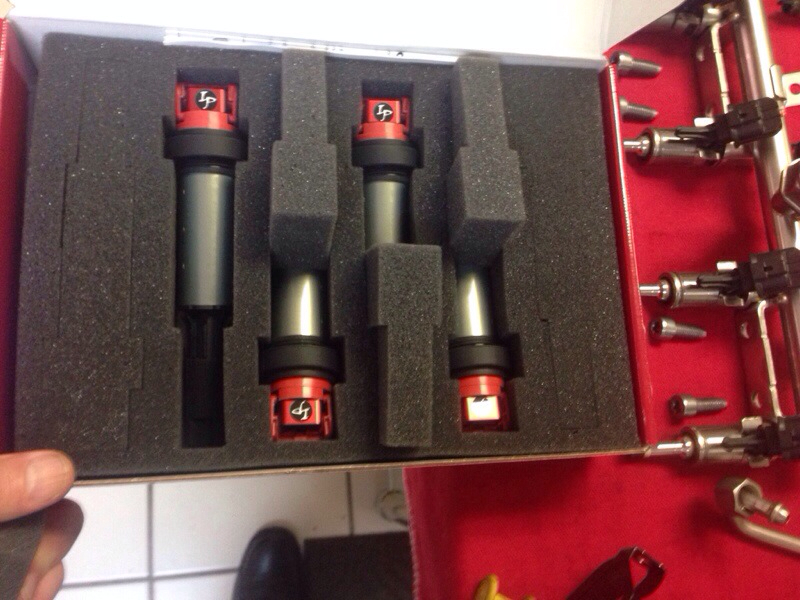
Should have Tigger back on the road next Friday to begin the breakin period. Also wanted to talk a little about ignition coils and plugs and how that relates to water/meth. For this build I've chosen Ignition Projects coils and Brisk silver plugs. The factory coils and NGK plugs work pretty good in our application. Adding water/meth up to an 80/20 mix also works well. Higher ratios then that however tend to result in less performance with more misfires.
During ignition a high voltage spark is created between the plug electrodes. This creates a flame kernel. If not disturbed this leads to a progressive flame front which travels outward in a controlled manner. As most know increasing boost on our platform also requires reducing the gap on the plugs. The primary reason is that the high air velocity and density present with higher boost will sometimes snuff out the flame kernel before it can propagate. Adding too much of a non combustible compound like H2O which works great at putting out fires only aggravates the situation. Since we don't want to lower boost we need to create a stronger spark and the two ways to do that is with a more powerful coil or by reducing the spark gap.
Since I'd like to try higher ratios of water/meth the coils and plugs were a must.
For the breakin tune I'll be running a custom tune based off of the factory tune to keep boost down but with two changes. The first change was to alter the secondary O2 system test as the DP has no cat. This self test is triggered periodically when the ECU is operating in closed loop mode and the engine RPM is below 3000. This self test subroutine now thinks the engine is always over 3000 rpm so it never reports an error. The second modification is to the MAP linearity table since I've refitted a JCW MAP sensor. These are 3.5 bar sensors as opposed to the standard 2.5 bar units that come on the S from the factory. Their voltage output limits are the same but the voltages generated now translate into different pressures so that table had to be altered.

Originally Posted by Tigger2011
Since we don't want to lower boost we need to create a stronger spark and the two ways to do that is with a more powerful coil or by reducing the spark gap.
Since I'd like to try higher ratios of water/meth the coils and plugs were a must.
Since I'd like to try higher ratios of water/meth the coils and plugs were a must.
thanks for all the awesome info thus far!

Joined: Jul 2013
Posts: 1,474
Likes: 248
From: Sunrise, FL
I'm not an electrical engineer but I'll gladly pass on the little I do know. Spark plug gap is really determined by three factors, engine compression ratio as it determines charge density, engine RPM and dwell time.
Dwell time is how long it takes to fully charge the coil. Since we use a single coil per cylinder it's not much of an issue. Older vehicles often used a single coil to fire eight or more cylinders which placed a huge load on the coil.
OEM's typically use larger spark gaps as it promotes a better idle and low to mid RPM efficiency but at high RPM the air inside the combustion is significantly more turbulent which again can snuff out the flame kernel but misfires will be less noticeable due to the increased RPM's. With our relatively low RPM range <7K this is not a huge issue but does have an small effect.
Charge density and compression ratio is where we run into a problem. Our dynamic compression ratio can exceed 15.5:1 and even 16.5:1 or greater. What many may not realize is that air is non conductive and acts more like an insulator as density increases making it harder for the coil discharge to bridge the electrode gap. Reducing this gap is the most simple and easy solution to implement, but not necessarily the best from a performance perspective.
In addition adding methanol to the mix adds another impediment due to its higher flashpoint. If switching to full meth performance engine builders typically recommend reducing your spark gap by an additional .005" to .010".
The IP coils quadruple the spark output, double the amperage and are multi discharge coils that fire 10 times per cycle instead of just once. If that doesn't get the fire lit I don't know what will. Iridium tipped plugs are great for longevity. Unfortunately the conductivity is not as high as traditional plug materials, but by reducing the tip diameter they can still do a very good job. The Brisk silver plugs are well...silver which has considerably higher conductivity both electrical and thermal but requires a larger electrode as it doesn't have the same hardness level as Iridium. Which means more frequent replacement. I mentioned earlier about trade offs and design philosophy. This is one of them.
I mentioned a book earlier in this thread about turbo charging and I'm going to recommend another one on performance that touches on ignition is several places. "Four Stroke Performance Tuning" by Graham Bell. Definitely worth picking up!! Some of it applies to dinosaur engines but there is still tons of great info in it we can use. I have several others that I have in my library at home. One called "Modern Engine Blueprinting" that I forgot to mention earlier, and several on engine tuning that I'll get to later on when we discuss tuning.
You always have great information, even when on vacation .
.
What gap are your Brisk plugs, one you get the car going 100%?
mQuebed Manic Tuning Dealer
. What gap are your Brisk plugs, one you get the car going 100%?
mQuebed Manic Tuning Dealer
__________________
2013 GP2 #295, 270whp/310wtq, KO4 47mm Turbo, 18" NM Wheels, Alta intake, Manic Stage III+, HFS-3 Meth, 30% E85 Blend, Forged IC, Alta Hot Pipe, P&P/Ceramic Exhaust Manifold, m3 Extreme Ceramic DP, Vibrant mid res, 4" Double walled Tips, WMW/KW V3 CO, Alta Rear CA, CREE Fogs, Black out F/R Rings and Gas Cap, M7 CF Front Splitter, and No Stickers. MORE TO COME!! Previous 04Triple Black 17% Alta, MM Air/H2O, CAI, OBX Header, FBT Head, Shrick Cam, 234whp
2013 GP2 #295, 270whp/310wtq, KO4 47mm Turbo, 18" NM Wheels, Alta intake, Manic Stage III+, HFS-3 Meth, 30% E85 Blend, Forged IC, Alta Hot Pipe, P&P/Ceramic Exhaust Manifold, m3 Extreme Ceramic DP, Vibrant mid res, 4" Double walled Tips, WMW/KW V3 CO, Alta Rear CA, CREE Fogs, Black out F/R Rings and Gas Cap, M7 CF Front Splitter, and No Stickers. MORE TO COME!! Previous 04Triple Black 17% Alta, MM Air/H2O, CAI, OBX Header, FBT Head, Shrick Cam, 234whp
Joined: Jul 2013
Posts: 1,474
Likes: 248
From: Sunrise, FL
Your welcome sir. As far as gap, my initial setting is going to be .027". That should be a good starting point. What I haven't decides on yet is which secondary knock sensor I'm going to install. Detonation on our cars should have a frequency of about 7.4 KHz and I want a secondary visual indicator to evaluate not only tuning while on the dyno and the road, but also to evaluate fuel sources as fuel quality can vary widely.