
How To DIY: Cheapest / Cleanest Aux install


Thread Starter
|
1st Gear
Joined: Mar 2011
Posts: 24
Likes: 0
DIY: Cheapest / Cleanest Aux install
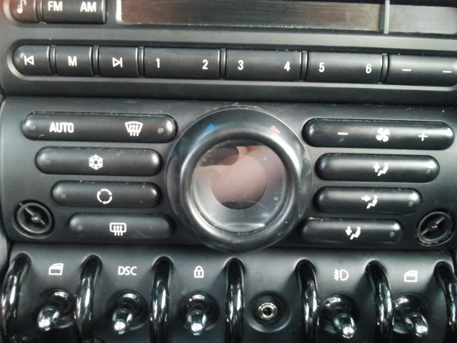
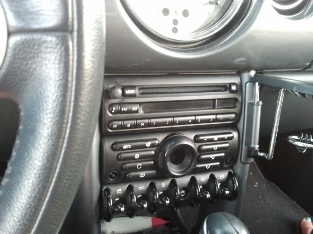
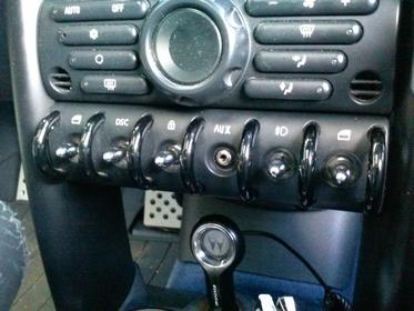
So after researching the issue of adding an auxiliary input to the girlfriend's mini cooper, I decided to go my own route and build it myself by using the open switch spot in the switch console.
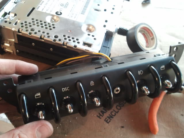
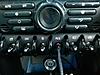
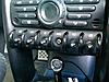
Finished product:
What you will need:
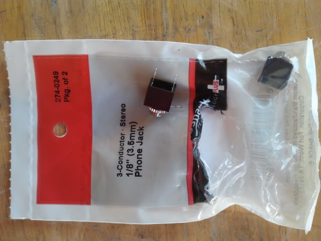
Aux input jack (bought two at radio shack for approximately 2.00 dollars)
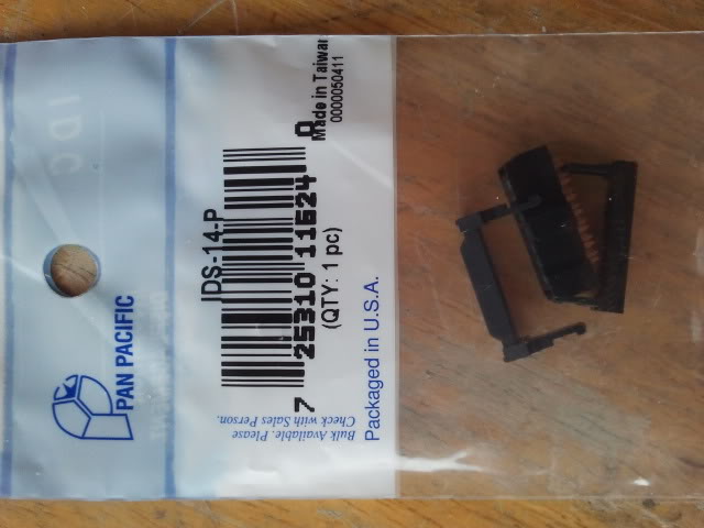
12 pin IDS female connection (bought at Frys for 1 dollar).
Wire
Electrical tape
Optional:
heat-shrink
Wire looming
Tools needed:
Torx bits
Drill and bits
Small flathead screw driver
Wirestrippers
Note: I am not responsible if you screw up anything...that is all.
Remember to always disconnect the battery before working on your car.
1. Remove knee bolster under the steering wheel simply by pulling down on it hard from the top.
2. Remove 2 torx bits on the downtube for each side
3. Pull downtubes forward to view the six torx bolts holding in the radio (4 bolts) and switches (2) - remove them.
4. Disconnect the two connections on the back of the radio and unscrew the black plastic nut holding the harness to the radio.
5. Remove the one connection on the back of the switches to pull out the switches.
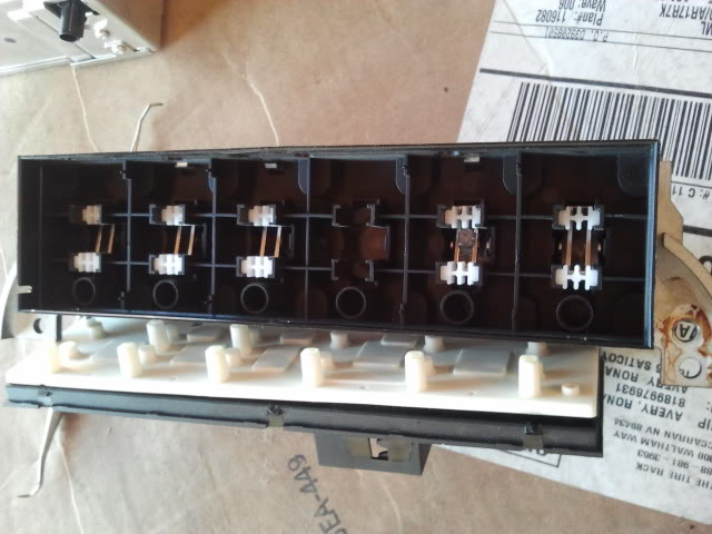
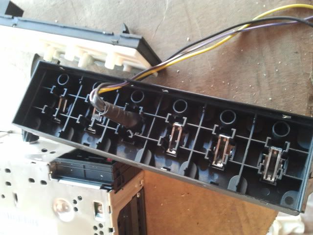
6. Once you have the switches out, remove the back cover by inserting a small flat head screwdriver to pop off the back cover/circuit board.
7. Next do the same thing (pop off six tabs) to remove the fascia of the switches.
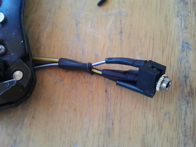
8. Wire up three wires to your aux jack to the correct poles (negative and both channels). Solder the connections and use heat-shrink
9. Drill a pilot hole directly in the middle of the area where there is no switch. Then drill a hole to match the size of your aux jack.
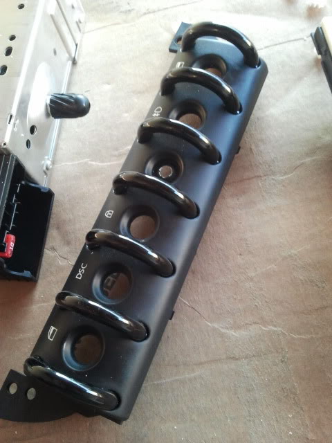
9b. This is an optional step, but for my jack, I had to shave off some of the back of fascia where the jack comes through so I could have it sit flush, and the nut of the jack can screw on with more threads.
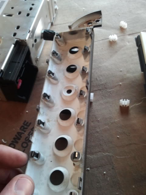
9. Cut off the two white rubber pieces that would normally go into the missing switch (cut for clearance of the jack).
10. Put the fascia and the switches back together to see how the jack/wires line up.
11. Trim some of the back to run wires out of the switch console.
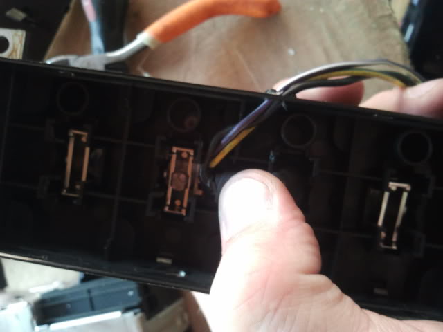
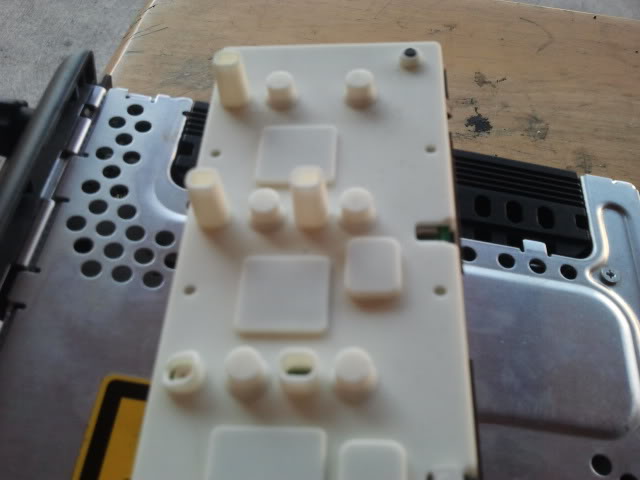
12. Run the wires through the small open hole on the top of the main switch console and reattach the back/board of the switches. Check all switches to make sure they feel like normal. If they feel loose, the wires are binding against the back and more trimming is needed.
13. Next pull out your 12 pin IDS (or if you can't find one like me pull out your 14 pin and shave it down to 12 pin so it will fit.
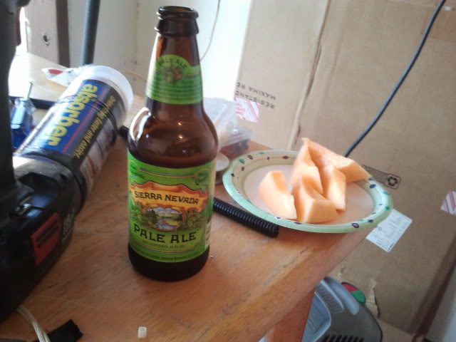
14. Take a break for a snack since the next part requires close up and steady hands/solder.
15. Attach the channels to pin #3 & 4 and the negative to pin #10.
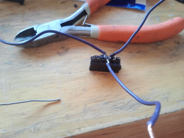
15b. If you have a 12 pin you can just put the wires in and attach the back to lock it, but if you can't just solder it so the wires stay in place.
16. Now run looming / tape to make it look cleaner/keep the wires together.
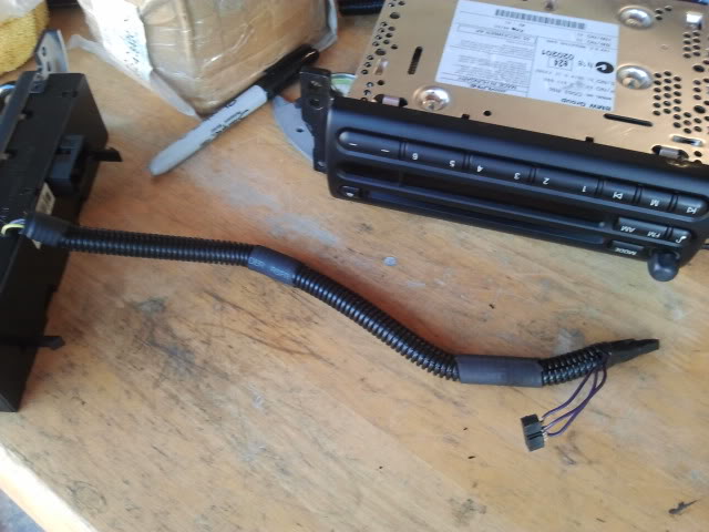
17. Reattach the switch console to the car, and run the newly installed wires up behind/above the climate control.
18. Attach the two OEM connections and your new IDS clip into the radio and mount it back up to the car.
19. Reattach downtubes and knee bolster.
20. Reconnect the battery negative cable.
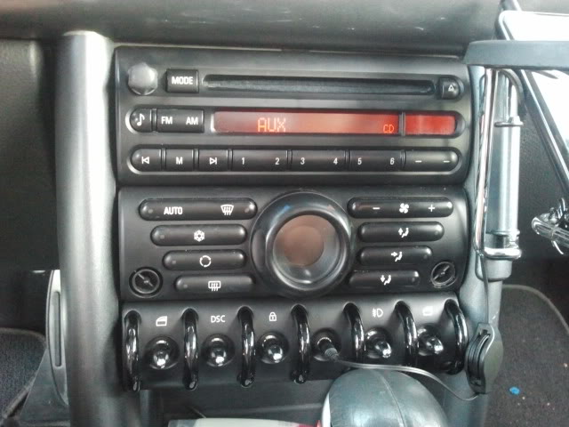
21. Turn on the radio hook up your cable to device and hit mode twice to get to aux.
22. Enjoy (also if it sounds low you can go through the stereo menu and you will see aux volume, turn it up to 5 to match the other modes volume).
Finished product:
What you will need:
Aux input jack (bought two at radio shack for approximately 2.00 dollars)
12 pin IDS female connection (bought at Frys for 1 dollar).
Wire
Electrical tape
Optional:
heat-shrink
Wire looming
Tools needed:
Torx bits
Drill and bits
Small flathead screw driver
Wirestrippers
Note: I am not responsible if you screw up anything...that is all.
Remember to always disconnect the battery before working on your car.
1. Remove knee bolster under the steering wheel simply by pulling down on it hard from the top.
2. Remove 2 torx bits on the downtube for each side
3. Pull downtubes forward to view the six torx bolts holding in the radio (4 bolts) and switches (2) - remove them.
4. Disconnect the two connections on the back of the radio and unscrew the black plastic nut holding the harness to the radio.
5. Remove the one connection on the back of the switches to pull out the switches.
6. Once you have the switches out, remove the back cover by inserting a small flat head screwdriver to pop off the back cover/circuit board.
7. Next do the same thing (pop off six tabs) to remove the fascia of the switches.
8. Wire up three wires to your aux jack to the correct poles (negative and both channels). Solder the connections and use heat-shrink
9. Drill a pilot hole directly in the middle of the area where there is no switch. Then drill a hole to match the size of your aux jack.
9b. This is an optional step, but for my jack, I had to shave off some of the back of fascia where the jack comes through so I could have it sit flush, and the nut of the jack can screw on with more threads.
9. Cut off the two white rubber pieces that would normally go into the missing switch (cut for clearance of the jack).
10. Put the fascia and the switches back together to see how the jack/wires line up.
11. Trim some of the back to run wires out of the switch console.
12. Run the wires through the small open hole on the top of the main switch console and reattach the back/board of the switches. Check all switches to make sure they feel like normal. If they feel loose, the wires are binding against the back and more trimming is needed.
13. Next pull out your 12 pin IDS (or if you can't find one like me pull out your 14 pin and shave it down to 12 pin so it will fit.
14. Take a break for a snack since the next part requires close up and steady hands/solder.
15. Attach the channels to pin #3 & 4 and the negative to pin #10.
15b. If you have a 12 pin you can just put the wires in and attach the back to lock it, but if you can't just solder it so the wires stay in place.
16. Now run looming / tape to make it look cleaner/keep the wires together.
17. Reattach the switch console to the car, and run the newly installed wires up behind/above the climate control.
18. Attach the two OEM connections and your new IDS clip into the radio and mount it back up to the car.
19. Reattach downtubes and knee bolster.
20. Reconnect the battery negative cable.
21. Turn on the radio hook up your cable to device and hit mode twice to get to aux.
22. Enjoy (also if it sounds low you can go through the stereo menu and you will see aux volume, turn it up to 5 to match the other modes volume).
6th Gear
Joined: Apr 2009
Posts: 1,361
Likes: 4
From: Yorktown, VA
Nice writeup. Just so you know, there is a similar post that does the same thing. One addition is he included a backlit LED and scraped in the iPod symbol into the panel.
https://www.northamericanmotoring.co...led-color.html
https://www.northamericanmotoring.co...led-color.html


1st Gear
Joined: Aug 2011
Posts: 40
Likes: 0
From: NYC
Great job! and thanks for the thorough guide and pictorial.I plan on doing a mod that will give me an aux in the glove box (along with USB and SD read capability) but i think the glove box is an inconvenient place for an aux input. I will use your pictorial to guide my installation of a jack in the lower console as you did.
Thread Starter
|
1st Gear
Joined: Mar 2011
Posts: 24
Likes: 0
Morning everyone, sorry for never replying back. Thanks for all the nice words, and as for the IDS connector's connection I am not sure what you mean. The radio simply has multiple pins sticking out that you need to connect to for the aux to work. The IDS connector simply pushes onto these pins and holds in place. As for functionality with previous model radios, I am sorry to say I have no idea. I am new to minis and just undertook this project for the girlfriend's car so I can't give any solid info on that subject. :(
Best of luck to anyone trying this, it is still working great and my
Best of luck to anyone trying this, it is still working great and my
Trending Topics

2nd Gear
Joined: Sep 2011
Posts: 57
Likes: 1
2nd Gear
Joined: Sep 2011
Posts: 57
Likes: 1
You inspired me  I did the same thing. Same crummy $3.00 radioshack plugs.
Instead of using an IDS connector I just used some old motherboard USB pins from an old desktop computer cable.
thanks for posting - mine came out great too!
I did the same thing. Same crummy $3.00 radioshack plugs. Instead of using an IDS connector I just used some old motherboard USB pins from an old desktop computer cable.
thanks for posting - mine came out great too!


Neutral
Joined: Jun 2010
Posts: 7
Likes: 0
Just completed this mod to my R53. Thanks to all who pioneered and presented good information via this forum. I used the wiring kit from Outmotoring, but didn't use the little plate, opting to run it thru the empty switch hole as shown in this post.
I also had the loose switch plate that needed to be fixed at the same time.
I also had the loose switch plate that needed to be fixed at the same time.


3rd Gear
Joined: Mar 2013
Posts: 203
Likes: 0
From: Somerset, MA
Have an Alpine deck in mine but the the aux in is a wire that comes out the glovebox.. wanted a more oem approach and had actually bought the same connector from radio shack prior to seeing this thread.. lol.. even engraved AUX on the panel..


Thread
Thread Starter
Forum
Replies
Last Post