
Drivetrain Intercooler Cooling Tests

My little dose of LITHIUM
iTrader: (1)
Joined: Jul 2005
Posts: 2,435
Likes: 2
From: Albuquerque New Mexico
mbcoops--did you put your hand on the IC horn after about 10 minutes? I think your observations are quite consistent with those of others. Driving on the track hard and fast for X minutes and then stopping is very different than tooling around from stoplight to stoplight at 6pm in the evening.

Also..
are you doing a cool down lap? That will cool things off quite a bit.
One way to see heat soak over a track session is top speed at the end of a straightaway. This is the time when you're hardest on the throttle for the longest time, but this will only work if your straight away entry speed is consistent.
AutoX can be a biatch for heat soak as well, as top speeds aren't that high, but "on power" time is a larger percentage of the drive.
Matt

6th Gear
Joined: Dec 2004
Posts: 2,047
Likes: 0
From: NJerz
Actually the cool down lap situation really pissed me off - Thunderbolt is still basically being built, so there are no flagger stations. The checkered flag would come out with 1/4 lap left, so I'd have that much cool down. To make sure I didn't hot-spot the brakes, I'd drive around the paddock in 1st gear for a while (less than 10 mph). That may be why the IC was cooler afterwards.
DrPhil - I'd check it once I stopped then again when it was time to go out again. If it was still warm by then, I'd put some water on it. No idea if that did anything helpful or harmful. Like I said, I go, stop and turn and hope the things I have no clue about work well enough. I can't complain about the performance of the car at all with its canned Dinan bolt-ons, street tires, and basically stock suspension.
The straight at Thunderbolt is very long when you consider you're full throttle out of the left carousel all of the way to the end of the actual straight. When I did it right, I'd clip 120ish (which is less due to my shorter tires) and felt no loss of power as each session went on.
mb

6th Gear
Joined: Mar 2006
Posts: 1,710
Likes: 1
From: Northampton MA
AutoX doesn't have the speed. Even an NA gets real hot. Picked up some marbles on the exhaust & had a small fire - a friend set some grass on fire with his RX7 - hot cat.......
Jan's spec is a good 1, 0 to 90 WOT & see what you get....
Jan's spec is a good 1, 0 to 90 WOT & see what you get....

funny thing is...........no one wants to post their inlet temps


5th Gear
Joined: May 2008
Posts: 855
Likes: 0
Geez, next you are going to say I have to put 250+ down without a LSD too. OK, I'm going to go out and play for a while, I'll log both and report back.

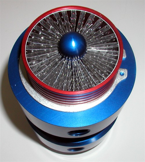
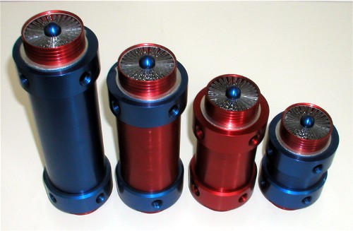
Round W/A Thermal Hard Pipes. I showed these a long time ago when they had an extruded fin design that was ok. Now they have a new fin design that looks real cool.
I could use this in place of the intake pipe that feeds my Rotrex. If I wanted to of course . Or you could use it to make a.......
Longboard
FROM THE MANUFACTURER:
The most visible change in this latest design is the new fin arrangement. There are 58 cooling fins in a radial pattern that are .008" thick. The thin fins allows for a quick transfer of heat. Each linear inch of the cooler has 101.5 square inches of heat transfer surface compared to our previous extruded design which had 37. The fins are over 12 times thinner for quicker heat transfer as well.
The claim of 101.5" is actually only temporary during the manufacturing process. Those same fins are perforated or punched with small holes over the entire fin surface which eliminates 15% of the original surface.
The most effective part of any cooling fin is the leading edge. It's referred to as the Frontal Boundry Area. By perforating the fins with holes, we have leading edges throughout the entire cooler giving us Frontal Boundary Area from the front of the cooler to the rear as the air passes across the effective half circles leading edges.
In addition to that, the fins are formed with a wave or curve back and forth to them called Ruffled. You cannot see through our coolers because of this. There are design considerations in this Ruffle called Pitch and Amplitude. If you think of it as waves in the ocean, the Pitch would be the distance between the waves and the Amplitude is the height of the waves. This is used to force the air to stay in more continual contact with the fin surface versus just sliding or slipping past it. While the air passes through the cooler, the air shifts from one side to the other and is allowed to move from one row to the other through the perforations finding the path of least resistance while contacting the Frontal Boundary Area. If this all sounds strange to you, consider this. The company that produces our fins claims this design is the only fin that was found to adequately cool the oil in the US Navy's V-22 Osprey Tilt-Rotor aircraft. Since they produce this same similar design for us as they do the Osprey, we can say with co
I could use this in place of the intake pipe that feeds my Rotrex. If I wanted to of course
. Or you could use it to make a.......Longboard
FROM THE MANUFACTURER:
The most visible change in this latest design is the new fin arrangement. There are 58 cooling fins in a radial pattern that are .008" thick. The thin fins allows for a quick transfer of heat. Each linear inch of the cooler has 101.5 square inches of heat transfer surface compared to our previous extruded design which had 37. The fins are over 12 times thinner for quicker heat transfer as well.
The claim of 101.5" is actually only temporary during the manufacturing process. Those same fins are perforated or punched with small holes over the entire fin surface which eliminates 15% of the original surface.
The most effective part of any cooling fin is the leading edge. It's referred to as the Frontal Boundry Area. By perforating the fins with holes, we have leading edges throughout the entire cooler giving us Frontal Boundary Area from the front of the cooler to the rear as the air passes across the effective half circles leading edges.
In addition to that, the fins are formed with a wave or curve back and forth to them called Ruffled. You cannot see through our coolers because of this. There are design considerations in this Ruffle called Pitch and Amplitude. If you think of it as waves in the ocean, the Pitch would be the distance between the waves and the Amplitude is the height of the waves. This is used to force the air to stay in more continual contact with the fin surface versus just sliding or slipping past it. While the air passes through the cooler, the air shifts from one side to the other and is allowed to move from one row to the other through the perforations finding the path of least resistance while contacting the Frontal Boundary Area. If this all sounds strange to you, consider this. The company that produces our fins claims this design is the only fin that was found to adequately cool the oil in the US Navy's V-22 Osprey Tilt-Rotor aircraft. Since they produce this same similar design for us as they do the Osprey, we can say with co

5th Gear
Joined: May 2008
Posts: 855
Likes: 0
Some General Data
The IC outlet is well over 200F when driven in anger, the OBD will read 150-180 due it's response and the averaging the T-MAP does. The stock intercooler will give about 120-130 temperature drop in most circumstances, which is close to Intense's data. One interesting data point, Intense took his peaks at 6800, wind it out to 7700 with a 17% and the SC outlet temps are 350+. Looking at how the T-MAP reacts, Jan's W2A is looking pretty good.
The IC outlet is well over 200F when driven in anger, the OBD will read 150-180 due it's response and the averaging the T-MAP does. The stock intercooler will give about 120-130 temperature drop in most circumstances, which is close to Intense's data. One interesting data point, Intense took his peaks at 6800, wind it out to 7700 with a 17% and the SC outlet temps are 350+. Looking at how the T-MAP reacts, Jan's W2A is looking pretty good.
here is the system big howe is using
Last edited by Revolution Mini Works; May 7, 2009 at 06:30 AM.


What would a 1% increase in air density be in regards to a PSI increase?
ACK!!!!!
What ever happened to basic math skills? It would be like a 1% increase in absolute pressure.
Anyway, pressure was the same, temp was a bit lower. But for a "boost" equlvalence, that's about 0.3 psi at constant temp, or about 3 C at constant pressure.
Matt
Anyway, pressure was the same, temp was a bit lower. But for a "boost" equlvalence, that's about 0.3 psi at constant temp, or about 3 C at constant pressure.
Matt
First tid-bit of GP data
I measured the pressure drop between a stocker and the GP, and guess what, the GP had a 6.5% HIGHER pressure drop! Effin' A!?!?!?! What's the deal?
FWIW, I have no clue, but with the increased cross sectional area, the gasses have a longer residency time in the core, and can cool more. But I'd have thought that the pressure drop would have been less.
Another possibility is that there are significant core to core variations, and I haven't measured enough stock cores to know what kind of variations to expect from how they're built!
But anyway, will wonders never cease!
Matt
PS, I'm running a coated GP IC on my car all the time.
Joined: Apr 2007
Posts: 702
Likes: 2
From: Utah
The more I look at things the more I like what I'm seeing from the GRS. Seems to me that even with the reduce in boost the air density is higher. This equates to a cooler more dense air charge which equals more power and smoother burn correct?