
DIY Water pump replacement in 2.5 hrs! (MCS ONLY!)


DIY Water pump replacement in 2.5 hrs! (MCS ONLY!)
I was tired of seeing write-ups/how-to's across the net that say you MUST remove the supercharger to service the water pump. This is simply not true, nor do I understand why it is recommended if supercharger service is not needed? You don't even have to remove the belt or the intercooler for that matter unless you prefer a little extra wiggle room.
Enter this DIY write-up! Back again with another to try and save YOU the Mini Cooper owner/enthusiast from having to pay ME the Technician a $1000+ service note!
Lets begin here.
Starting with required tools and parts. (part #'s are OE Mini and may differ slightly from vin to vin)
Parts.
Replacement Mini Cooper S Water Pump (comes with new o-ring)
11 51 7 520 123
Water Pump Flange (comes with new o-ring)
11 51 7 509 170
Supercharger to Intake Duct Gasket
11 61 0 020 836
Throttle Body Gasket
13 54 7 509 045
Mini OE Coolant (if you prefer it)
82 14 0 031 133
Sil-Glyde (pick it up at Napa!)
NAPA Part# 765-1351
A/C WILL NEED TO BE PROFESSIONALLY RECHARGED!
Tools.
Ratchet ( 3/8 preferred, and a 1/4 as well )
6-10" Extension ( 3/8 )
8mm socket ( 1/4 inch w/small extension )
13mm socket ( 3/8 )
10mm socket (3/8)
3/8 Ratchet Swivel
T30 Torx Bit/Socket ( I have a master set, but you can get these at your local parts store)
Medium length pry bar, or long FLAT head screwdriver
#2 Phillips Head screwdriver
Flat Head screwdriver
Pair of normal pliers
Pair of Diagonal cutters
Small catch pan/drain pan/bowl?
Small mallet or hammer
Safety glasses
Pack of latex gloves
I did all of this without air tools which could have possibly cut about another 5-10 min off my time, but THIS IS ALL HAND POWERED no AIR TOOLS!
Last edited by BoostCzaR53; Dec 28, 2012 at 06:08 PM.
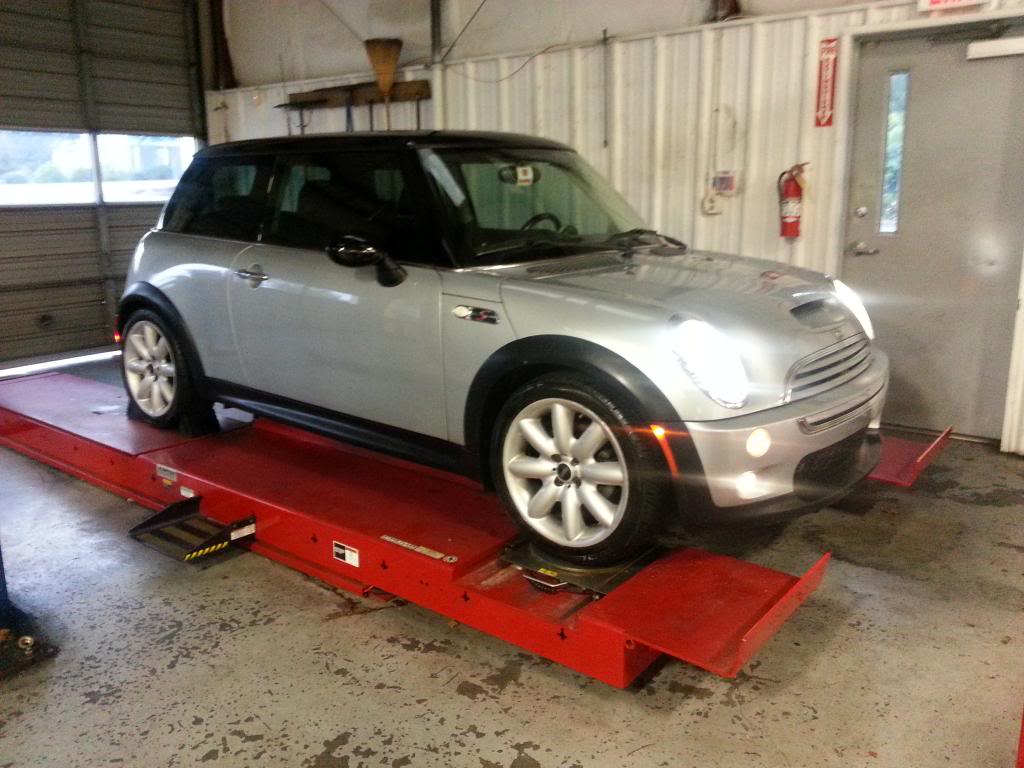
Here we go....your basic BONE STOCK 02 MCS! OR R53 as the purists call it. (Pure Silver FTW!)
Now according to AllDataPro, the service manual calls for over 5.9 hours to do this, it wants you to remove the supercharger? I think thats quite ridiculous!
We are going to start by pulling the car up on ramps if you have them, jack the front of the car up on jack stands, or like I did just use your handy $5000 lift at your local Acura dealer haha!
Regardless if you do raise the front of the vehicle in any manner just make sure its properly secured and wheels are chocked in some manner! I am not responsible for your "I crushed my chest" threads.
Anyways, lets get the front of the car elevated slightly, dont need much. Start with popping the hood first, you are going to want to turn the wheels full lock one direction or other, doesnt really matter so you can reach the 2 bolts that require the 8mm socket.
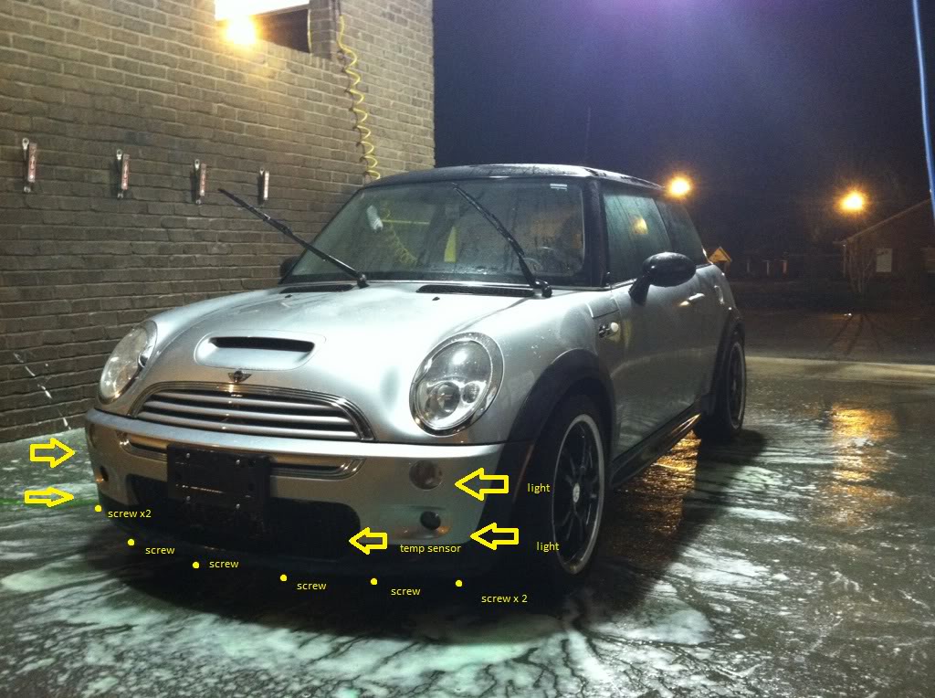
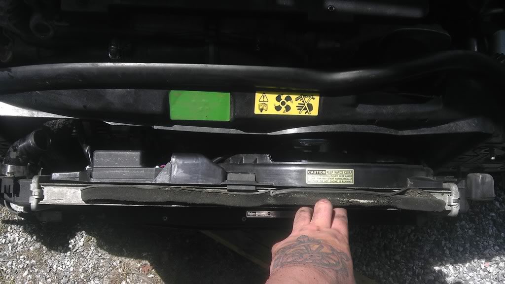
Reach under the front of the car below the grill, you will find about 8-10 screws along the bottom of the front bumper just below the chin of the front bumper. Mine was missing a few so I had 2 on each corner, and 3 along the front, yours may vary. (see picture for reference)
Take your #2 Phillips head screwdriver and remove these screws!
Yes I have stock wheels back on my MCS, as the first picture shows!

Now according to AllDataPro, the service manual calls for over 5.9 hours to do this, it wants you to remove the supercharger? I think thats quite ridiculous!
We are going to start by pulling the car up on ramps if you have them, jack the front of the car up on jack stands, or like I did just use your handy $5000 lift at your local Acura dealer haha!
Regardless if you do raise the front of the vehicle in any manner just make sure its properly secured and wheels are chocked in some manner! I am not responsible for your "I crushed my chest" threads.
Anyways, lets get the front of the car elevated slightly, dont need much. Start with popping the hood first, you are going to want to turn the wheels full lock one direction or other, doesnt really matter so you can reach the 2 bolts that require the 8mm socket.
Reach under the front of the car below the grill, you will find about 8-10 screws along the bottom of the front bumper just below the chin of the front bumper. Mine was missing a few so I had 2 on each corner, and 3 along the front, yours may vary. (see picture for reference)
Take your #2 Phillips head screwdriver and remove these screws!
Yes I have stock wheels back on my MCS, as the first picture shows!
Once these screws are removed, you have 4 more left to remove the entire bumper cover!
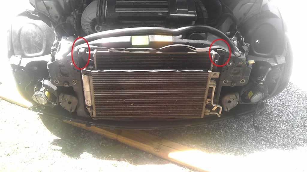
YOU WILL NEED TO REMOVE THE 2 OUTSIDE 8MM BOLTS, AND THE 2 T30 TORX BOLTS TO REMOVE THE BUMPER COVER FIRST! THEY ARE LABELED IN THE PHOTO BELOW!!! TO GET TO THE 8MM BOLTS YOU MUST GO FROM THE BOTTOM WHICH IS WHY I HAVE THE WHEELS TURNED FULL LOCK SO YOU CAN REACH THEM.

Once you have removed those, you will be able to pull the front bumper off, you should be able to grab near the center of the bottom and pull upwards and off as it kind of slides into little slots on the top.
Upon removal you will see a metal crash bar, which is not in picture here I already removed it before I took this picture. The 13MM bolts you need to remove to take the crash bar off are labeled in the picture coming.
Before pulling the bumper cover separate of the car you will need to unplug the light bulbs and temp sensor or they will pull out themselves via breaking, or tearing the wires! see picture for reference.
YOU WILL NEED TO REMOVE THE 2 OUTSIDE 8MM BOLTS, AND THE 2 T30 TORX BOLTS TO REMOVE THE BUMPER COVER FIRST! THEY ARE LABELED IN THE PHOTO BELOW!!! TO GET TO THE 8MM BOLTS YOU MUST GO FROM THE BOTTOM WHICH IS WHY I HAVE THE WHEELS TURNED FULL LOCK SO YOU CAN REACH THEM.
Once you have removed those, you will be able to pull the front bumper off, you should be able to grab near the center of the bottom and pull upwards and off as it kind of slides into little slots on the top.
Upon removal you will see a metal crash bar, which is not in picture here I already removed it before I took this picture. The 13MM bolts you need to remove to take the crash bar off are labeled in the picture coming.
Before pulling the bumper cover separate of the car you will need to unplug the light bulbs and temp sensor or they will pull out themselves via breaking, or tearing the wires! see picture for reference.
Here comes the bulk of the hand tool use!
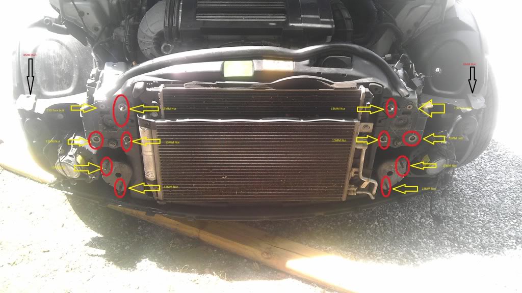
I have circled below in red, forgive me I know the picture references are crude, I have circled the 10 (13mm bolts) that you will need to remove to remove the front crash bar! You will need that extension here!
Grab that extension and that 13MM socket and strap em together! Remove all 10 circled bolts/nuts here, and slowly remove the crash bar to make sure that no harnesses or wires get tangled in it!
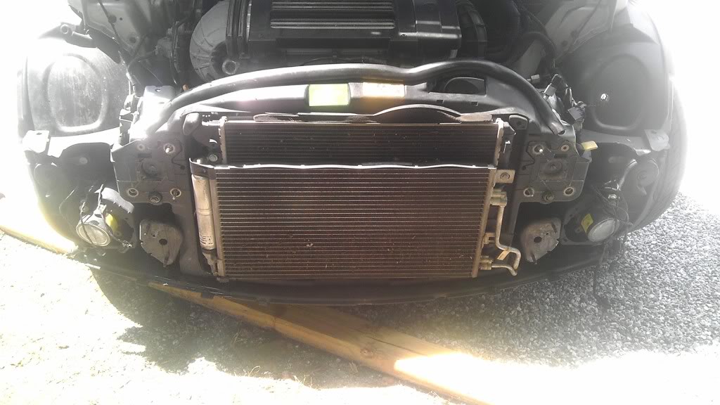
Once the crash bar is removed, you are left with this....
Now we are to loosen up this fan shroud/condenser/radiator setup.
In the picture shown below you will see 2 circles in red, in these circles will be 2 push pins, just simply grab those diagonal cutters and pull the center pin out, and once it pulls out, pull the whole piece out with the rubber pieces with holes in them that are still present in the picture!
Now with that done, we need to remove that top radiator hose from the neck of the radiator. My hose has an aftermarket worm clamp on it so I used a screwdriver to take it off, yours might still require pliers because it is the OE squeeze clamp. Be careful to make sure the coolant isnt piping hot when you start to do this, or that there isnt any pressure on the system, if not sure just slowly loosen the coolant reservoir cap to relieve the pressure on the system. Slide that catch can/drain pan/bowl whatever you have handy underneath the passenger front side of the car relevant to the radiator hose position to catch that coolant!
Now that you have the radiator hose off, the whole assembly should have some play to it. Try putting your hand on her and softly pulling forward to see if you have the same amount of play as pictured below!

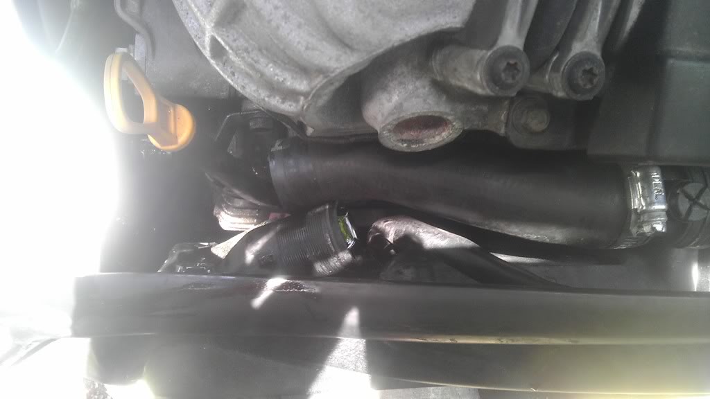
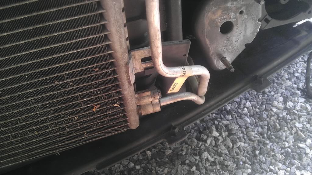
[SIZE="5"]BE SURE NOT TO PULL TOO HARD OR TOO FORWARD YOU WILL KINK OR DAMAGE THE AC LINES POSSIBLY! THE LINES I AM SPEAKING OF ARE PICTURED BELOW! THEY ARE DOWN AT THE DRIVER SIDE BOTTOM CORNER OF THE AC CONDENSER![/SIZE]
Now we are to loosen up this fan shroud/condenser/radiator setup.
In the picture shown below you will see 2 circles in red, in these circles will be 2 push pins, just simply grab those diagonal cutters and pull the center pin out, and once it pulls out, pull the whole piece out with the rubber pieces with holes in them that are still present in the picture!
Now with that done, we need to remove that top radiator hose from the neck of the radiator. My hose has an aftermarket worm clamp on it so I used a screwdriver to take it off, yours might still require pliers because it is the OE squeeze clamp. Be careful to make sure the coolant isnt piping hot when you start to do this, or that there isnt any pressure on the system, if not sure just slowly loosen the coolant reservoir cap to relieve the pressure on the system. Slide that catch can/drain pan/bowl whatever you have handy underneath the passenger front side of the car relevant to the radiator hose position to catch that coolant!
Now that you have the radiator hose off, the whole assembly should have some play to it. Try putting your hand on her and softly pulling forward to see if you have the same amount of play as pictured below!
[SIZE="5"]BE SURE NOT TO PULL TOO HARD OR TOO FORWARD YOU WILL KINK OR DAMAGE THE AC LINES POSSIBLY! THE LINES I AM SPEAKING OF ARE PICTURED BELOW! THEY ARE DOWN AT THE DRIVER SIDE BOTTOM CORNER OF THE AC CONDENSER![/SIZE]
Last edited by BoostCzaR53; Dec 28, 2012 at 08:56 PM.
This next step is VASTLY important to pay attention to! You really should have your A/C discharged professionally for this, but if you choose not to worry about it, then lets move on! *I CLAIM NO RESPONSIBILITY NOR IMPLICATIONS BROUGHT UPON THE USER FOR POLLUTION OF ATMOSPHERE* DO THIS AT YOUR OWN RISK*
With your 13mm socket and 10mm socket, remove the four bolts circled in red below, careful to remember if you have not had your A/C discharged breaking loose and removing the two 10mm bolts from the condenser lines will release A/C refrigerant into the atmosphere, which is illegal by EPA standards and YES it does mean you need a recharge after your done. CAREFUL TO WEAR SAFETY GLASSES AND DO NOT INHALE OR MAKE SKIN CONTACT WITH THE REFRIGERANT!
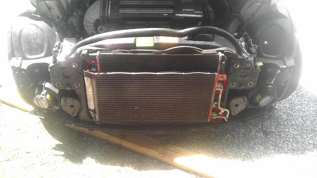
This step will finally set the condenser and radiator/fan in position to be removed!
With your 13mm socket and 10mm socket, remove the four bolts circled in red below, careful to remember if you have not had your A/C discharged breaking loose and removing the two 10mm bolts from the condenser lines will release A/C refrigerant into the atmosphere, which is illegal by EPA standards and YES it does mean you need a recharge after your done. CAREFUL TO WEAR SAFETY GLASSES AND DO NOT INHALE OR MAKE SKIN CONTACT WITH THE REFRIGERANT!
This step will finally set the condenser and radiator/fan in position to be removed!
Now carefully separate the lines from the condenser when ready, and remove the condenser from the radiator. Next, lean the radiator forward as pictured below. Carefully unplug the fan and pull the harness and connectors free of the car and remove the cooling fan.
Now lean the radiator forward and grab those pliers to squeeze the lower radiator hose clamp. Once you have slid the hose clamp back, carefully wiggle the lower radiator hose free from radiator outlet. BE CAREFUL! THESE INLETS/OUTLETS ON THESE RADIATORS ARE PLASTIC AND WITH LOTS OF MILEAGE CAN BECOME BRITTLE AND CRACK OR BREAK OFF!
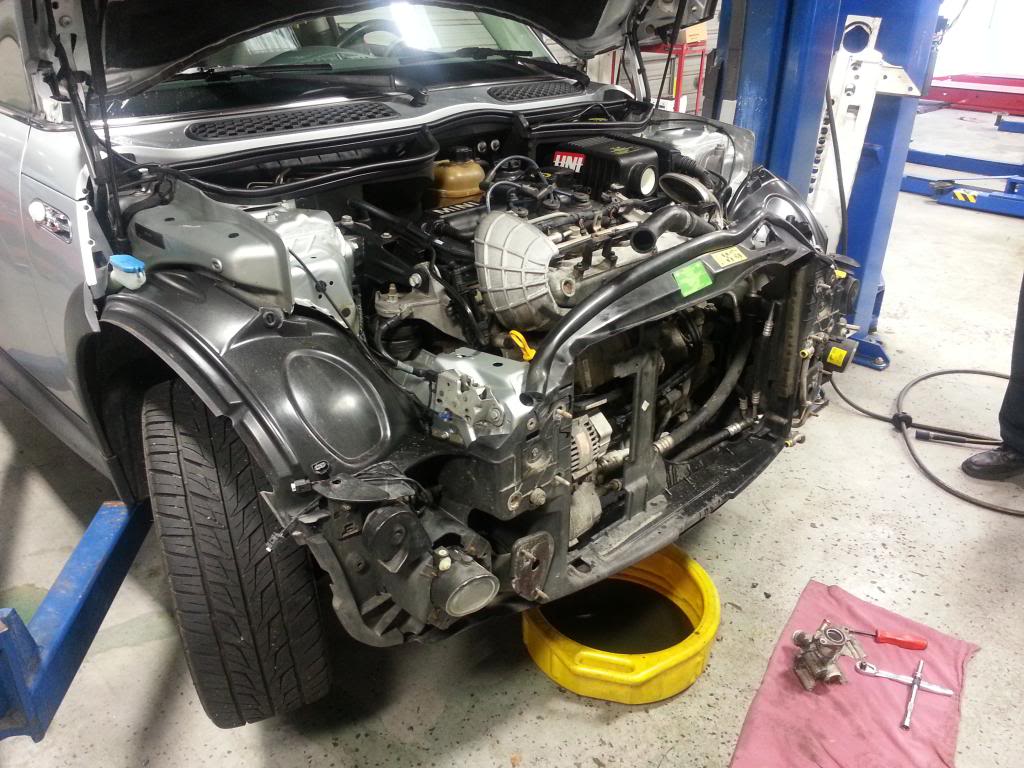
By now the front end of your MCS should look like mine pictured below, front bumper, bumper support, A/C Condenser, cooling fan, and radiator all removed and moved away from your work area!
Now lean the radiator forward and grab those pliers to squeeze the lower radiator hose clamp. Once you have slid the hose clamp back, carefully wiggle the lower radiator hose free from radiator outlet. BE CAREFUL! THESE INLETS/OUTLETS ON THESE RADIATORS ARE PLASTIC AND WITH LOTS OF MILEAGE CAN BECOME BRITTLE AND CRACK OR BREAK OFF!
By now the front end of your MCS should look like mine pictured below, front bumper, bumper support, A/C Condenser, cooling fan, and radiator all removed and moved away from your work area!
Trending Topics
Next, take that ratchet (whatever size you chose) and attach an extension to it, and the T30 Torx socket on the end. Remove the four T30 Torx bolts holding the black plastic diverter on top of the intercooler and remove the diverter itself. Now take the same tool and remove all eight T30 Torx bolts used to clamp the four clamps onto the black rubber intercooler couplers. Once clamps are removed, it will take some delicacy but wiggle the intercooler out by sliding it to the left and raising the right side of the intercooler out and therefore giving room to remove it from the left side. VOILA! Intercooler removed!
Sorry I didnt get any pix for this step :( but you should have the same result as you can see in my picture above!
Sorry I didnt get any pix for this step :( but you should have the same result as you can see in my picture above!
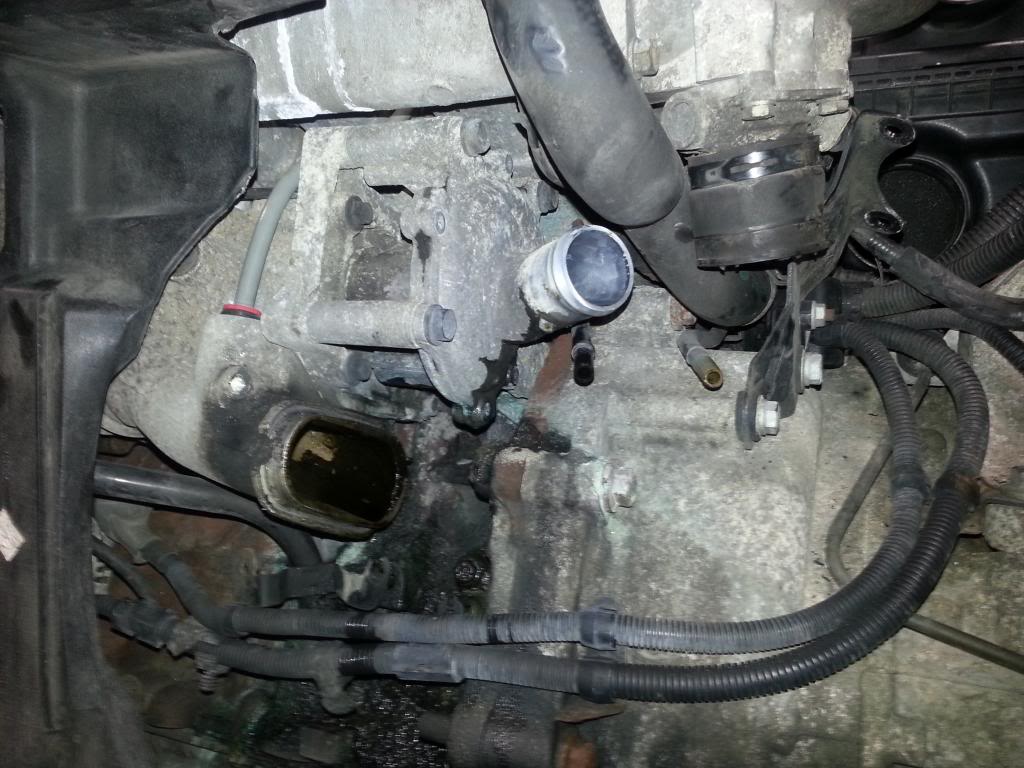
Now lets get that nasty, smelly, troublesome headache of a water pump out!

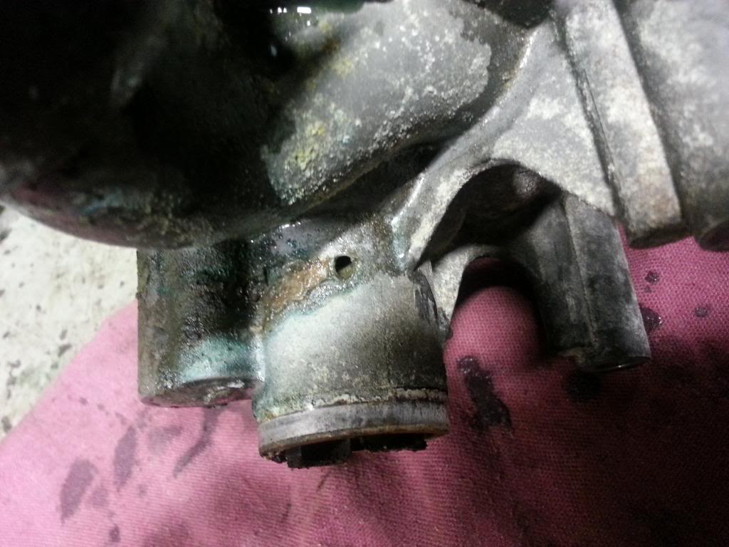
UGGGHHH!!! As you can see, the coolant was seeping out of the weep hole on the pump itself, running down the body of the pump and getting sucked into the blower, as evident by the sludge buildup on the inside wall of the blower inlet. See pictures above and below.
In order to gain access to the water pump as pictured above, there are still a few more components that need to be taken off!
Start by grabbing that ratchet, and extension and a swivel, attach a 10mm socket to all that. Look for the throttle body, it will be connected by a rubber intake tube to the air filter box. Start by loosening the connection to the air box, to give you some wiggle room and play. Take the previous listed tool, and loosen the four bolts holding the throttle body down, and take them out. (sorry no picture of this step). Proceed to move the throttle body off the black inlet tube that leads to the blower inlet. Careful to notice the small vacuum line clamped onto the throttle body housing, and the electrical connector for the throttle body controller.
Next, start by taking those pliers and getting that other side of the bottom radiator hose off, it will be connected to the larger of the outlets on the water pump. Pull that hose off carefully as not to tear it.
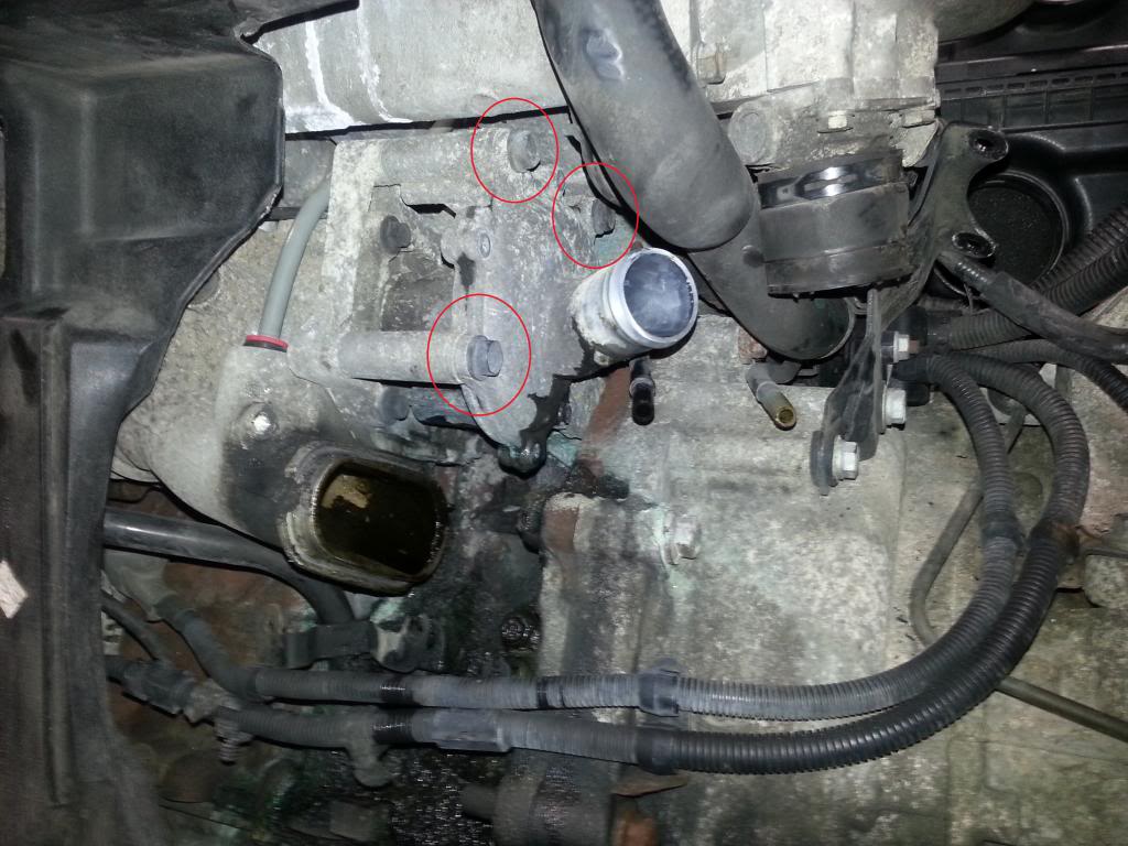
The next part is quite tricky, and if not done carefully can cause some headaches of replacing vacuum lines and if reckless can cause you to crack the supercharger inlet tube. You must be quite careful and do the next step in the sequence stated to prevent damage to your vacuum lines!
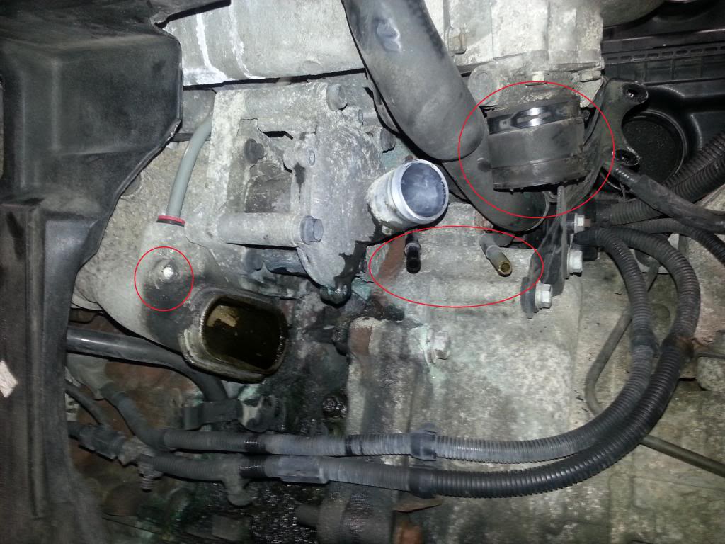
Disconnect the two vacuum lines circled in the center of the picture above, they are connected to the black inlet tube by time you have reached this step. There should be two red plastic rings around the two vacuum lines while they are plugged in, these are quick release locking clips for the lines. Release the two vacuum lines by pushing on the red collars around the lines and slightly tugging the lines out of the hole, dont be scared to pull them out and then out of the way but be careful and cautious. Next step is to remove the 10mm bolt that is marked by the circle in the left of the picture, pretty simple step there. Third, we need to remove the clamps on the rubber bypass hose circled in the right side of the picture, to be able to remove the black supercharger inlet tube.
Once all components/pieces are released/removed in this order we are now ready to wiggle the inlet tube out!
Take caution with this step so to not break anything. Carefully slide a flat head in between the rubber bypass hose and the plastic part of the inlet tube. Try to separate the two all the way around the bypass. Once separated, wiggle and wiggle, saw a few curse words, and wiggle some more. Chances are if you have any mileage on your Mini, it will be as difficult to slide off as mine was! SHEWWWWWWW, once done with that part slide the inlet tube to the right and it should disconnect from the blower inlet leaving you with this view, or similar at least!
The water pump fully revealed, the supercharger inlet revealed, and freedom to shine a light into the area of the engine block that it is covered by the water pump.
The next part is quite tricky, and if not done carefully can cause some headaches of replacing vacuum lines and if reckless can cause you to crack the supercharger inlet tube. You must be quite careful and do the next step in the sequence stated to prevent damage to your vacuum lines!
Disconnect the two vacuum lines circled in the center of the picture above, they are connected to the black inlet tube by time you have reached this step. There should be two red plastic rings around the two vacuum lines while they are plugged in, these are quick release locking clips for the lines. Release the two vacuum lines by pushing on the red collars around the lines and slightly tugging the lines out of the hole, dont be scared to pull them out and then out of the way but be careful and cautious. Next step is to remove the 10mm bolt that is marked by the circle in the left of the picture, pretty simple step there. Third, we need to remove the clamps on the rubber bypass hose circled in the right side of the picture, to be able to remove the black supercharger inlet tube.
Once all components/pieces are released/removed in this order we are now ready to wiggle the inlet tube out!
Take caution with this step so to not break anything. Carefully slide a flat head in between the rubber bypass hose and the plastic part of the inlet tube. Try to separate the two all the way around the bypass. Once separated, wiggle and wiggle, saw a few curse words, and wiggle some more. Chances are if you have any mileage on your Mini, it will be as difficult to slide off as mine was! SHEWWWWWWW, once done with that part slide the inlet tube to the right and it should disconnect from the blower inlet leaving you with this view, or similar at least!
The water pump fully revealed, the supercharger inlet revealed, and freedom to shine a light into the area of the engine block that it is covered by the water pump.
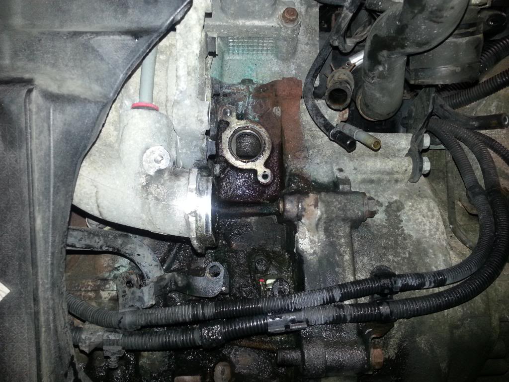
You are now 3 bolts away from yanking that cursed water pump out, and only 5 away from removing all of the water pump components in full! Congrats pat yourself on the back and have a beer or a snack at this step, you have come a long way!
These 3 holding the water pump in, and 2 behind the water pump you wont be able to see until its removed.

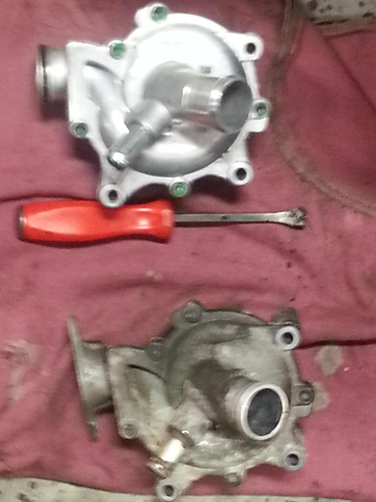
This is the water pump flange, listed in the parts list BTW. ^^^^
Lets jump to it, I have a wife cooking up an aromatically enticing meal as I type this!
Lets grab a hold of a 13mm socket, extension and swivel along with that ratchet. Start by removing the three bolts on the water pump. Remove the bottom bolt first, moving to the next one above it, you may not need an extension and swivel for the middle bolt there, I didnt. Once that one is removed, start on that very far back bolt, that is closest to the engine block and marked by the 3rd bolt circled in red and slightly off to the right. You will need to stand up and slide the extension, swivel an socket through the mess of wires and upper radiator hose and loosen and remove that third and final water pump bolt.
These 3 holding the water pump in, and 2 behind the water pump you wont be able to see until its removed.
This is the water pump flange, listed in the parts list BTW. ^^^^
Lets jump to it, I have a wife cooking up an aromatically enticing meal as I type this!
Lets grab a hold of a 13mm socket, extension and swivel along with that ratchet. Start by removing the three bolts on the water pump. Remove the bottom bolt first, moving to the next one above it, you may not need an extension and swivel for the middle bolt there, I didnt. Once that one is removed, start on that very far back bolt, that is closest to the engine block and marked by the 3rd bolt circled in red and slightly off to the right. You will need to stand up and slide the extension, swivel an socket through the mess of wires and upper radiator hose and loosen and remove that third and final water pump bolt.
Last edited by BoostCzaR53; Dec 28, 2012 at 05:46 PM.
This next step might call for the use of that pry bar and maybe a small mallet. Try and tap and wiggle the water pump and possibly pry in between the fingers that mount it to the supercharger to break it free, mine happened to be pretty well sunk into place, the mix of corrosion build up and rust and so forth made for a slight wiggle or two with some prying to pop it loose of the blower drive gear.
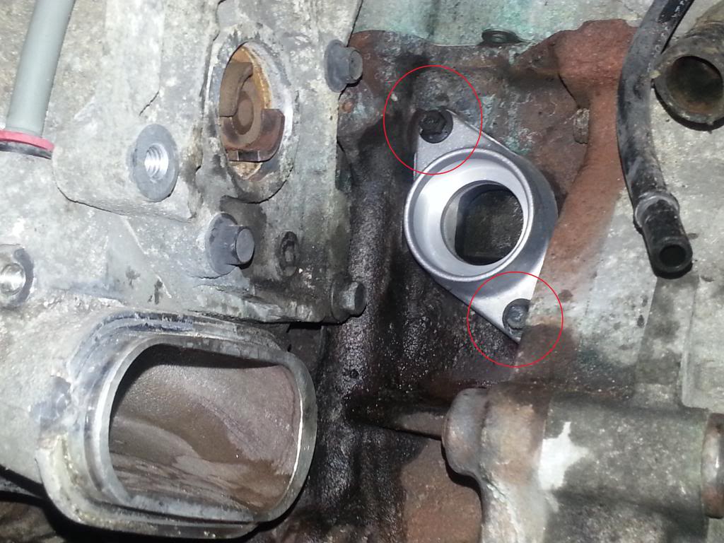
Once popped loose you will see the flange shown earlier behind there with two bolts holding it in.
Remove the flange, by simply removing the two 10mm bolts circled in red here. After removing, use some sort of scotch brite pad and/or very fine grit sandpaper to smooth up the mating surface and clean off any coolant residue.
Before moving onto the next step, a few prep steps need to be taken. Read carefully.
Check the back of your new water pump, it will have a two toothed gear that looks identical to the one seen on the supercharger. Align the gear on the pump to be able to push into place and mate up with the gear on the back of the supercharger. Before putting the water pump in, go ahead and bolt that new water pump flange back into place, just snug up those bolts, nothing extremely tight. Take that new water pump and with a swab of Sil-Glyde lube the o-ring on the water pump so it will easily slide into the new flange without rolling up or tearing. See pix below for reference!
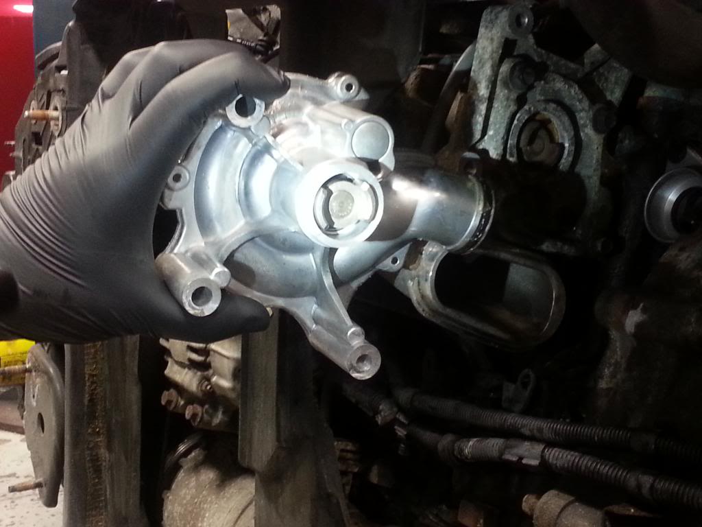
NOTE! PICTURE OF WATER PUMP ONLY TO SHOW GEAR DESCRIBED ABOVE, NOT TO SHOW ORIENTATION or LINE UP OF WATER PUMP TO INSTALL!
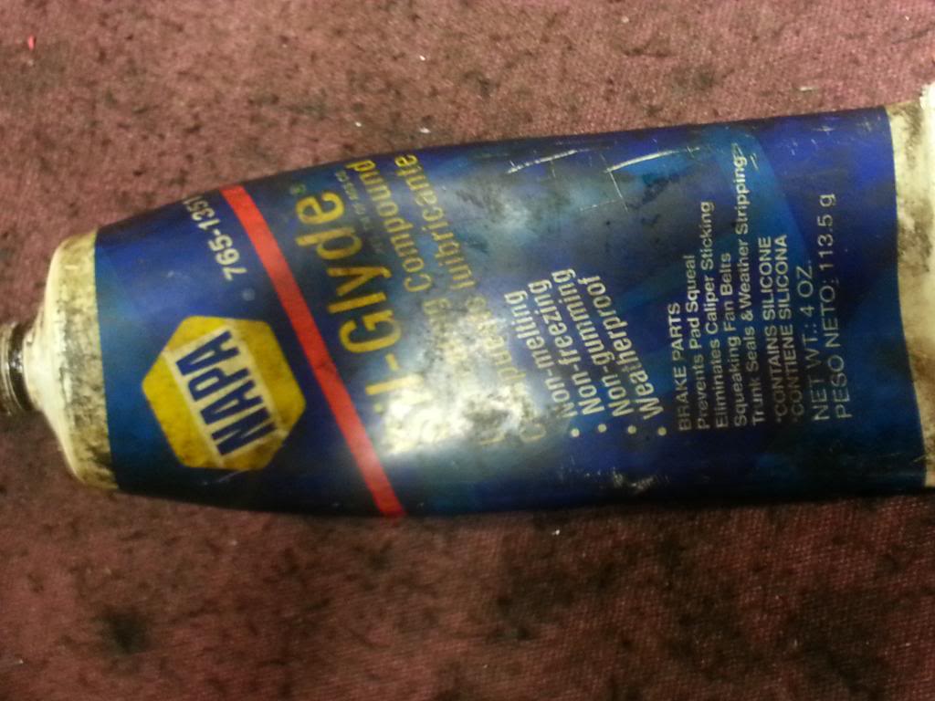
THIS IS SIL GLYDE!!!^^^^^
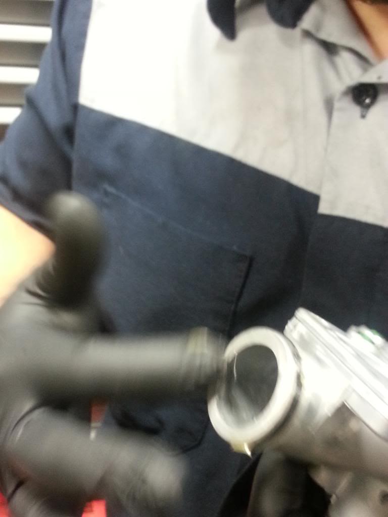
Lube the water pump o-ring like shown.
Check the back of your new water pump, it will have a two toothed gear that looks identical to the one seen on the supercharger. Align the gear on the pump to be able to push into place and mate up with the gear on the back of the supercharger. Before putting the water pump in, go ahead and bolt that new water pump flange back into place, just snug up those bolts, nothing extremely tight. Take that new water pump and with a swab of Sil-Glyde lube the o-ring on the water pump so it will easily slide into the new flange without rolling up or tearing. See pix below for reference!
NOTE! PICTURE OF WATER PUMP ONLY TO SHOW GEAR DESCRIBED ABOVE, NOT TO SHOW ORIENTATION or LINE UP OF WATER PUMP TO INSTALL!
THIS IS SIL GLYDE!!!^^^^^
Lube the water pump o-ring like shown.
After installing the new water pump flange and lubing the water pump o-ring, make sure the gear on the pump is aligned to slide into the supercharger. Re-install the components taken off in this procedure in the reverse order of taking them off. Make sure the pump gets pressed back into the supercharger and the mounting fingers line up flush with the blower. Tighten all your bolts, plug all vacuum lines back in and re-clamp all hoses and tighten properly. Upon re-assembly add coolant back into the system and bleed properly by turning your heat on to full throttle and filling the reservoir with coolant and allowing the car to bleed the system of air bubbles. Allow the heat in the car to get hot coming out of the vents. After all is done, have your A/C professionally recharged.
If you have any questions, comments, concerns or need me to fill you in on a section that is missing a picture or ANY MATTER OF ANY SORT! PLEASE SHOOT ME A PM! ILL BE MORE THEN GLAD TO HELP! Sorry for the runoff of procedures and so forth, probably a mis-spelled word in there or so.
HERE TO HELP MY FELLOW CAR ENTHUSIAST SAVE A GRAND! I DO CAR SERVICE FOR A LIVING, IF YOU WANT ME TO COME BY AND HELP JUST ASK!
Happy Motoring!
More write-ups to come in the future:
DIY Intercooler Diverter Upgrade
DIY Lower Control Arm Bushings
DIY Serpentine Belt Replacement (WITHOUT MINI BELT TOOL!)
Thanks for reading!


I sure hope so! This is quite a common leak on these vehicles, and is quite EXPENSIVE to have a shop perform.

Neutral
Joined: Jun 2011
Posts: 6
Likes: 0
Thanks
There are some good tips in your writeup. I printed it out and had it with me while working on my wifes mini.
Two comments that may help others:
1- It is not that much more work to pull the whole radiator assembly off and leave the condensor in place. Pelican parts has a diy on this. the extra steps required to remove the radiator mount are offset by the additional work and cost of recharging the system and replacing the dryer.
2-It is possible to remove the 2 flange bolts and the three water pump bolts and remove the flange and pump components as an assembly. Otherwise movement is a bit restricted.
Thanks for the kind words people!
Great write-up! What else have you done?
__________________
Your Trusted Source For DIY and Parts
FREE SHIPPING over $99 click here
MINI Parts | DIY Help | Facebook | Twitter | Instagram | YouTube | Promos
888.280.7799 | 6am - 5pm PST

FREE SHIPPING over $99 click here
MINI Parts | DIY Help | Facebook | Twitter | Instagram | YouTube | Promos
888.280.7799 | 6am - 5pm PST
I have done the lower control arm bushings, diy intercooler diverter and radiator fan removal. Just havent finished the writeups due to busy work schedule


Awesome write up and congrats. 
Water pump here: 11517520123 old part number, newest number 11511490591
https://www.ecstuning.com/Mini-2005-Cooper-R52-S-Convertible-L4_1.6L_W11B16A/Engine/Cooling/Water_Pump/
Kits here:
https://www.ecstuning.com/Mini-2005-Cooper-R52-S-Convertible-L4_1.6L_W11B16A/Engine/Cooling/
Water pump here: 11517520123 old part number, newest number 11511490591
https://www.ecstuning.com/Mini-2005-Cooper-R52-S-Convertible-L4_1.6L_W11B16A/Engine/Cooling/Water_Pump/
Kits here:
https://www.ecstuning.com/Mini-2005-Cooper-R52-S-Convertible-L4_1.6L_W11B16A/Engine/Cooling/
__________________

MINI Guru/ MINI Owner Since 2004 | NEW Lifetime Part Replacement | Local Pickup
Milltek | Genuine MINI | Forge Motorsport | NM Engineering | ECS Performance | M7 Speed
Customer Service Hours: 8am-8pm EST|Sales Team Hours: 8am-11pm | SAT 10am-7pm 800.924.5172
MINI Guru/ MINI Owner Since 2004 | NEW Lifetime Part Replacement | Local Pickup
Milltek | Genuine MINI | Forge Motorsport | NM Engineering | ECS Performance | M7 Speed
Customer Service Hours: 8am-8pm EST|Sales Team Hours: 8am-11pm | SAT 10am-7pm 800.924.5172
Last edited by ECSTuning; Dec 27, 2017 at 11:47 AM.


FYI, the OP, while contributing a helpful DIY, also stiffed a couple of NAM members by not shipping parts that were purchased from him. He went AWOL, "Over the hill", vanished. Reflected badly on Tarheel MINI folks. We don't take kindly to scam artists.