When you click on links to various merchants on this site and make a purchase, this can result in this site earning a commission. Affiliate programs and affiliations include, but are not limited to, the eBay Partner Network.
Navigation & Audio OpenAuto Pro Custom HU Build Log
Navigation & AudioBring your GPS and favorite CD or MP3. This is where navigation and audio options for the Cooper (R50), Cabrio (R52), and Cooper S (R53) MINIs are discussed.
Going to log some progress here. This project might crash and burn but maybe a good solution can come out of it for these first gen coopers. I expect updates to come slowly but I will post them as I go for anyone following along.
I'm currently using OpenAuto Pro and I like it for the most part. But I want to step up the game a bit. I spent so much time working on cracking the kombi to swap from chrono gauges to sat/nav (https://www.northamericanmotoring.co...hopefully.html) that by the time I was done there I was too spent to focus on a proper HU build. Some pics of the current setup can be found here (https://www.northamericanmotoring.co...lity-help.html). Most of that thread is a confused mess as i had no clue what I was doing at the time.
I've taken the measurements of the current sat/nav system and the plan is to create a solution that will be able to fit cleanly into the current housing. A Raspberry Pi will be the brains and PCB800099 video controller. I'm also keeping track of some of this on the OAP site as well. I was hoping to get some help for the crew over there but parts of this are pretty specific (like the pcb shape).
I had a document of thoughts but the formatting was a mess when I tried to paste it here so pics attached instead.
Prototype of the smaller control board for the menu button, rotary encoder, and lux worked as intended. The bigger main board has been a little more interesting. I didn't fully understand one of the ic's I was using so I'm still working through a few issues.
Here is the PCB render of the smaller board along with how it came out. I had to change the photoresistor I was using since the original was a victim of the shortage. The new one was smaller and i misplaced it about 1mm too high it looks like. I might try to heat the clear plastic piece and bend it slightly to see if I can get it to work. Everything fits almost exactly as the original.
Update on this project.
V1.1 has turned out pretty well. Made 2 big mistakes. Messed up the design on the hub because I used a revised datasheet but selected an older chip. That part I could have been okay without since I don't really need a hub. But the other mistake was missing a connection from the touch controller to the pi. That mistake hurts a bit since... ya know, touch screen without a working touch and all.
What I do have working though:
12V power convert to 5V3A to power the pi (and peripherals).
Comprartor for delayed power shutdown
Line audio out
Accessroy switch sense for power down
Reverse sense turns on backup camera
Illumination sense turns on secondary board lights.
OBDII (read through usb)
RTC to keep time when powered off
***KBUS Not yet tested***
***PWM for LCD not tested yet***
I also de-soldered the connection from the original nav unit and I'll be able to solder it to the new board so I can re-pin the connector and use the original part.
Doing a redesign now for V1.2.
And since I like pain, I'll make a few changes and add different parts.
- Moving some of the holes in the board for more convenient connections.
- Going to make the hub bus powered instead of self powered.
- Will make sure I don't eff up and forget the trace for the touch screen this time.
- Adding an ADC (was using hub mic, but ADC on board means I can use a smaller mic)
- Adding a high side switch
- Also working in timer idea that will turn on the unit when it senses the door unlock. That will make boot seem shorter and might be fully loaded once buckled and ready to go.
Looks like you’ve not gotten much interaction in this thread! I think it’s pretty cool what you’re doing here, even though I don’t understand it at your level. I find it fascinating that people like you exist, and can tinker about in your workshop to come up with an alternative solution to the factory interface. Good work!
Thanks @njaremka . Its been a learning process. Designing for my car, but the thought is that when I'm done, even a novice can order the board and raspberry pi and retrofit this to their own vehicle in a few hours. The prototype I've been running for 2 years now has been great. really nice to have carplay / anroid auto in the car.
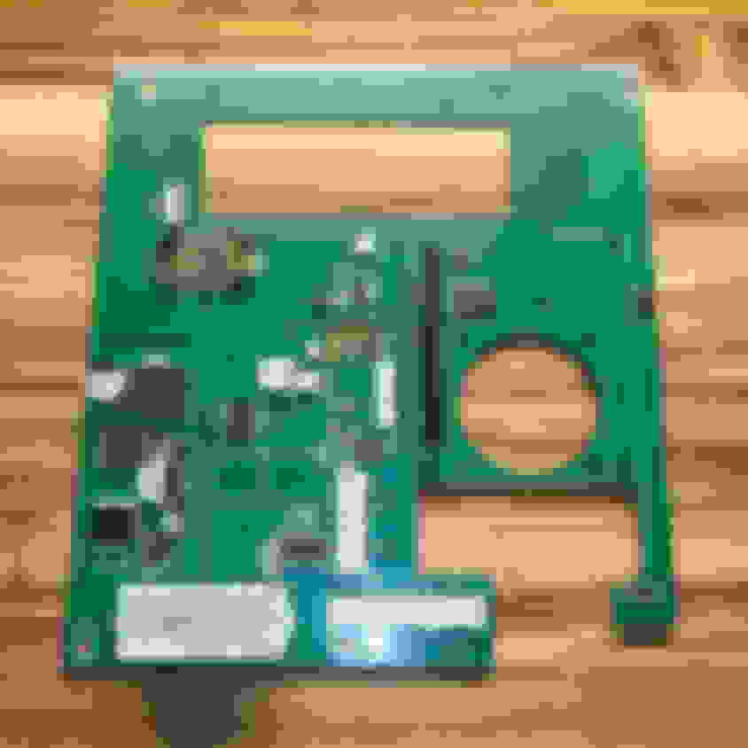
I now have the new board with revisions designed and sent out to be printed. I'll have it back in a few weeks. In the meantime I guess I'll take apart another spare I have and document the process here. This is what I did with the old unit so that I can keep the car looking as stock as possible.
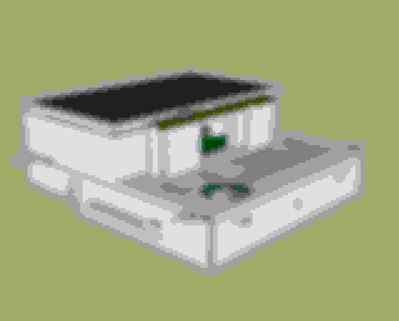
First, I took the old navigation unit out of the housing its in. There are 6 screws on the side holding the top and bottom casing together.
Separate the 2 halves.
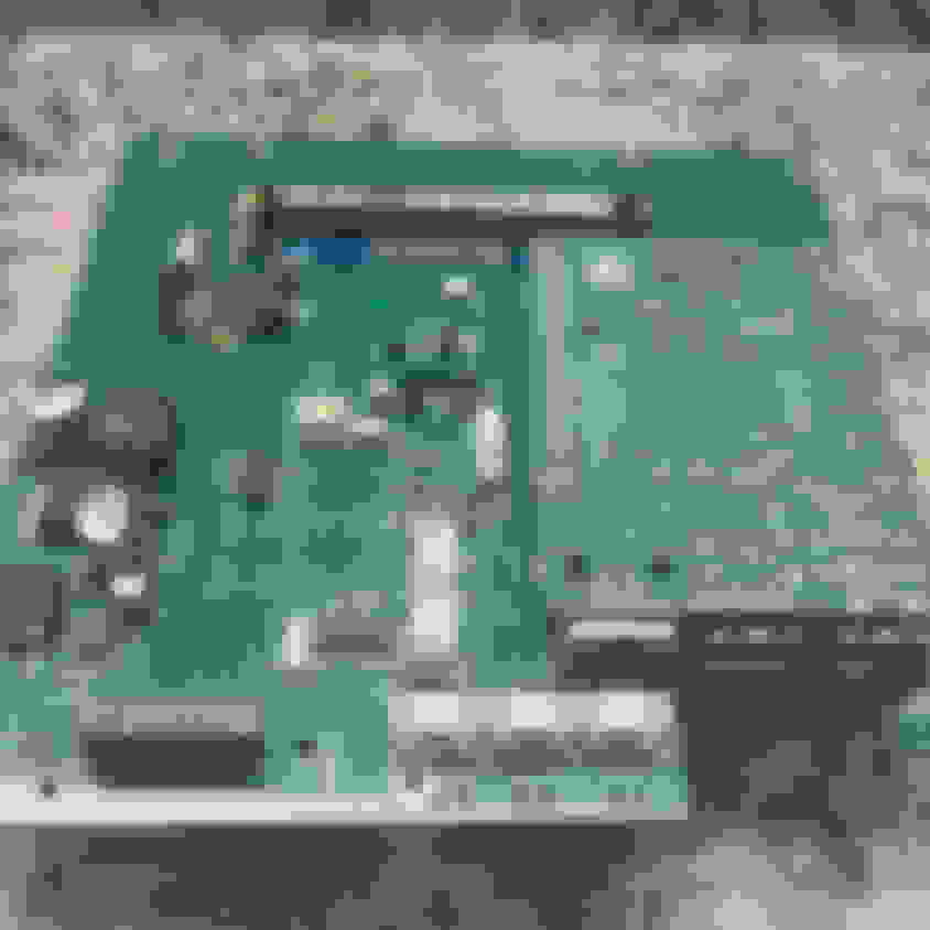
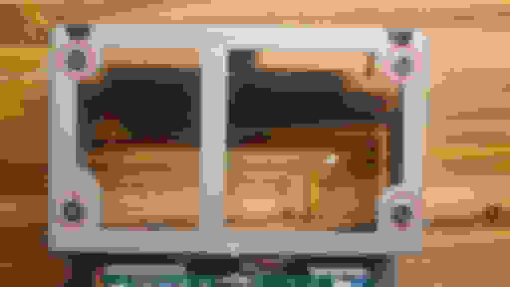
Take the side with the screen and circuit board and flip it over. Remove 4 connectors, 1 screw, and then de-solder the 4 pads holding the board in place.
Use some flux and a wick and pull the solder up, then use some wires to twist the metal tab straight on all 4 sides so the board can be lifted out.
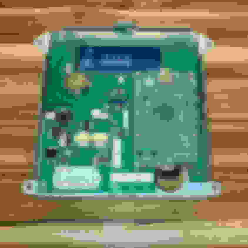
There are 4 screws on the back side securing the video screen. After that, all parts separated like this.
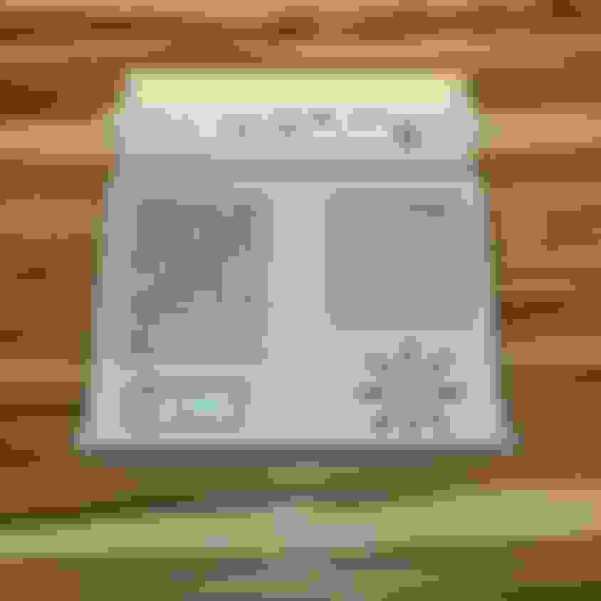
Next to disassemble the screen. Its pretty easier to see all the snaps holding it together. The only piece I’m interested in though is the back plate that has the mounting bracket attached to it. Since the new screen is slightly bigger than the old one, I used a dremel to cut the tabs off so I can fit it to the new screen.
Once the bracket plate is cleaned up, attach it to the new lcd screen with some jb weld. These are the measurements, I also took 80 grit sand paper and scuffed up the mounting surface of each side and then cleaned it with alcohol.
Don’t smush the jb weld into the lineup marks, or add so much it comes out the mounting hole. I ended up having to take a little bit and drilling out the hold so I could mount it. Not a prob though since I got it before it hardened all the way.
Don’t smush the jb weld into the lineup marks, or add so much it comes out the mounting hole. I ended up having to take a little bit and drilling out the hold so I could mount it. Not a prob though since I got it before it hardened all the way.
Since the old screen was a little more thick than this new one, add a washer to it. I used some from a long forgotten project. They are probably #4 or #6. The first 2 setups I created I used only a single washer. This time I will be using 2 washers (even thought only 1 in the pic).
Since I opted not to use a super long rotary encoder this one is a bit squished in there. The plastic around the **** needed to be trimmed slightly.
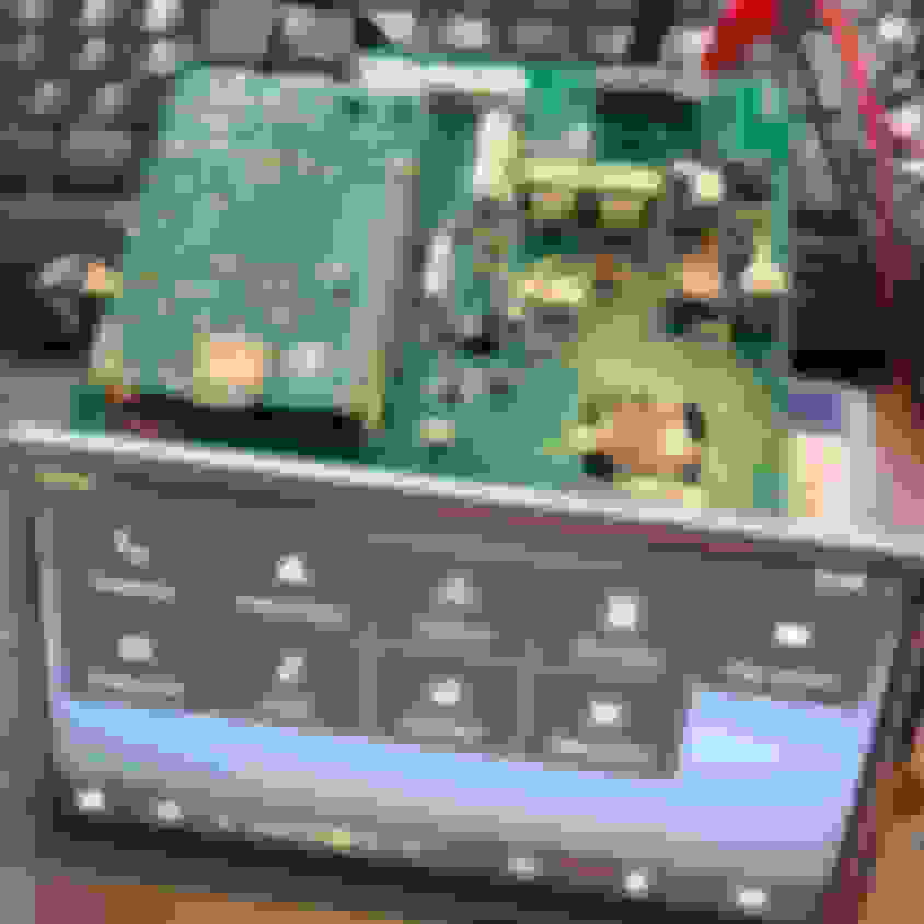
I also took the old board and removed the original connector. The board I designed take this connector into consideration so that it can be soldered in and the original plug from the car can be re-pinned and used here as well. This was pretty simple, I added some flux, a little extra solder and then took the wick and heated the solder covering the screws holding the connector to the board. I then added a long line of solder to all the pins and heated the entire are while I used some pliers to gently pull the connector out.
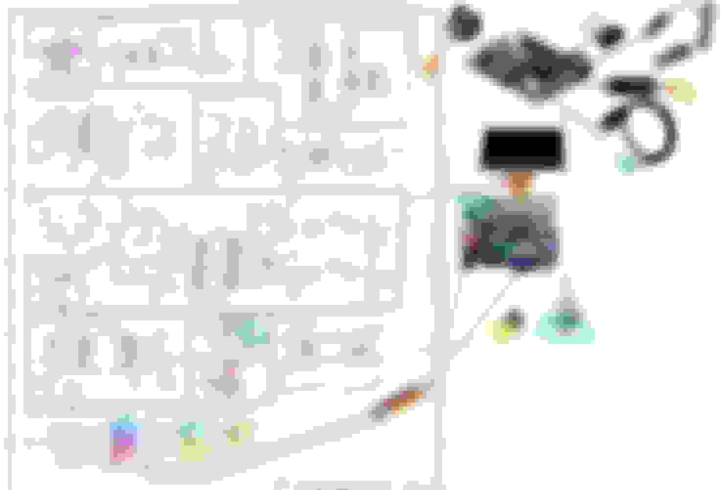
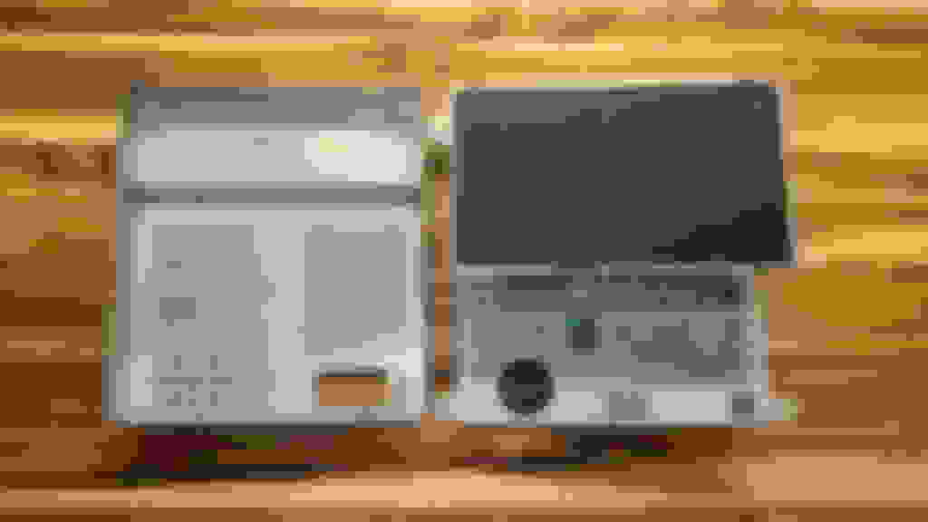
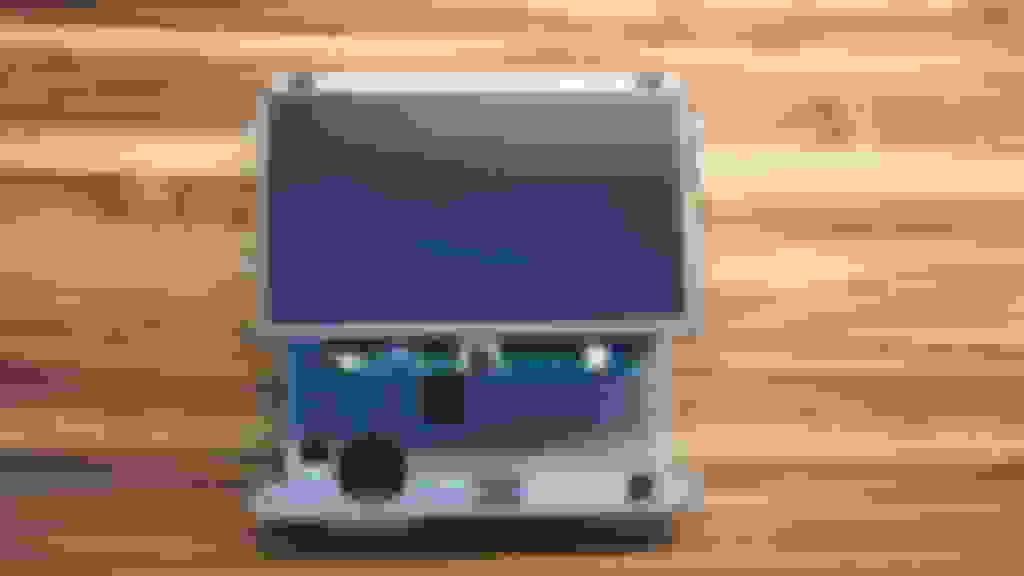
Here is the new LCD screen with the resistive touch controller added. The tails just tuck under the unit and down in the cage.
And now I just need to wait from my re-designed board to arrive. Should be here in about 8 weeks. I didn't build a prototype with the changes I made so I'm really hoping I didn't miss anything this time around.
Last edited by AutoMutt; Sep 20, 2023 at 05:38 PM.
Just to comment on your door sense idea, that�s exactly how bmw does their nav boot up, on r53, e46, e39 e53, etc etc and even up to modern cars. When there is ibus activity, ie door unlocked via remote or cylinder, door is opened etc you can hear the drive start spinning up so that by the time you are in an key in ignition it is ready.
Also a back or home key might be the better choice vs voice activation on the center stack, especially since there is a voice activation button close at hand on the MFL steering wheel controls that you might be able to somehow read and interpret. And on the wheel is a much better place than reaching out to center stack I can tell you from experience in my f31.
If you are the nice fellow who figured out the pin out etc to revirginize Chronos with a r270, thanks. I got to get rid of my useless nav (my whole side of town didn�t even exist 10 years ago when final map update came out) and get a working temp gauge instead thanks to that.
Last edited by Onizukachan; Sep 26, 2023 at 10:15 PM.
There wasn't a whole lot of interest in this, and I got sidetracked in another project and forgot about it.
I've been using some form of OpenAuto Pro since 2019. After owing a few of the cheap android units (my son still has one in his car), I don' think I could go back. OAP is really great for my needs. I've already spent a couple hundred dollars on this thing and it works as I need it so I don't plan to continue to develop it. But, I'll leave some notes here for you if you want to try to play with it a bit. The schematics are still there on easy eda and can be cloned so anyone can edit them.
I'm using this with the original timer I bought back in 2019. The time was originally connected to the door lock, so that when the car was unlocked the timer would trigger and the system would load. But, with the car unlocked it wouldn't trigger. So instead I wired it to the door light. As soon as the door opens the system loads.
Things that are working well:
1 - Power with timer. In the bluewavestudio.io forums, there are a number of safe shutdown options used with the timers. I have customized one of them to work with this board.
2 - Backup Camera. You need an EasyCap plugged into the a USB port, and the camera connected to the trigger wire and it works great. A second option is to plug the video cable directly into the video controller board, and connect the trigger wire to the 12v AV2 trigger and you bypass the RPi completely and don't need and EasyCap.
3 - Powered USB hub. Provides 5v which won't fast charge a phone, but will charge while using it in USB mode.
4 - Illumination. When you turn the headlight on, the menu button lights up and looks oem
5 - ALS (Ambient Light Sensor). The sensor in the front of the unit (opposite of menu button) has an ALS that can be used to switch to day/night mode if desired.
6 - Ignition Sensor. The unit shuts down as needed between the timer and the script based on the accessory input.
7 - Input (Rotary Encoder and resistive screen). I mentiond the touch controller could use some help,but using the adafruit controller - I can say the resistive touch screen is the way to go. Much better than capacative if you are in a humid climate, have dry hands, use the screen after working out with super sweaty hands... also, the rotarty encoder to scroll back and forth, enter, go back, and switch menus workes really well. The menu button also works well for the home screen and to switch between scroll/dimming mode on the rotary endocer. ALSO - you could edit the script to change the interactions here for something that suits you better if you wanted. ie - instead of menu being a home button, you could set it to activate Google Assistant, etc.
8 - OBDii. The obdii data showing up on the RPi is nice to have. Not really necessary, but cool anyway.
9 - RTC (Real Time Clock). If you forget your phone, the rtc is acurately keeping time for you. This was super annoying in the first build I did not to have.
Things that could be addressed to make this thing perfect:
1 - Power Circuit. The hardware on Ver1.2 is not correct. In Ver1.1 I was only using 3.3v, but with the addition of the powered USB hub I needed to up it to 5v. This required changing the power circuit and I didn't test it before making the change. A hardware power mode would be ideal.
2 - Touch Controller. The unit has a AR1021 chip. The RPi recognizes it but touch is not registered. I bought a cheap board from adafruit to get around this.
3 - Video Controller. This is not part of the board, but needs to be recognized. I am using an old PCB800099 green board in the build in my car and its perfect with dimming and turning on/off (and no OSD popups). I tried to buy a few more, but the other 3 were the blue boards. The green board as a TI PT4103 chip that is great for dimming with PWM. The blue board uses a DI AP3032, on paper it has 2 dimming options and looks good, but I could never get it to work properly. Try to get the green board if you can, or know that the dimming is lackluster with the blue board.
4 - Microphone Input (ADC) - I used a PCM1808 ADC and a PCM5102 DAC. The DAC is fantastic, but the 1808 really gave me trouble figuring it out. Even after I did get it figured out, the quality was not to my liking and I ended up using a USB condenser mic that sounds great. In the RPi forums you'll find others with a similar experience with the 1808. If revising the board and you want and ADC, I'd choose a different chip.
Untested:
iBus. I designed this based on a circuit found online for BMW. In theory it works so you can decode the signals from the steering wheel to take advantage of all those extra buttons. But I have not yet had time to test it.
Here is a short video of the unit that might answer some questions -