Navigation & Audio My Audio Upgrade Installation


My Audio Upgrade Installation
Hi All,
I've been wanting to post this for quite some time, but am just now getting around to it. The system was installed last June, about two months after I got the car. I have an '07 R56 MCS that came pretty heavily optioned, including the HiFi (ne, noFi!) system.
I completely designed the system and layout in advance and spec'd out the equipment. I had a professional installer do the fun part - my back and neck have done too many of these to make it much fun anymore. I also wrote up detailed installation instructions and provided the installer with a lot of the fantastic technical diagrams others have posted here. Although the installers had done other MINIs, they were grateful to have the wiring diagrams, the door dismantle instructions, the connector pin diagrams, etc. I also loaned them my digital camera and asked them to document the installation as they went along.
I am EXTREMELY pleased with how it all came out, both in audio quality and in looks. My goal was to have a somewhat stealth installation so that by just looking at the car, you really couldn't tell that it wasn't stock. But I also wanted it to be dynamic, have plenty of headroom, image well and have tight, integrated bass - not a BOOM BOOM system. My musical tastes are quite eclectic, so it needed to sound good regardless of what type of music I was playing. It wasn't specifically designed to be a "Rock" system or "Classical" system, or anything like that.
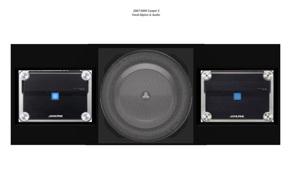
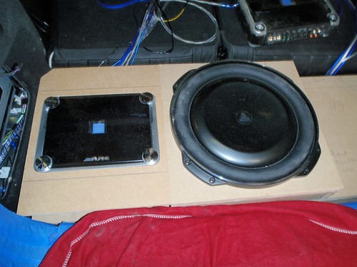
But first, here are the major components that would be going in:
Over the next few days I'll post highlights of the installation as it progressed. I'll also post links to more photos for those who want to see more of the details.
Cheers,
Tom
I've been wanting to post this for quite some time, but am just now getting around to it. The system was installed last June, about two months after I got the car. I have an '07 R56 MCS that came pretty heavily optioned, including the HiFi (ne, noFi!) system.
I completely designed the system and layout in advance and spec'd out the equipment. I had a professional installer do the fun part - my back and neck have done too many of these to make it much fun anymore. I also wrote up detailed installation instructions and provided the installer with a lot of the fantastic technical diagrams others have posted here. Although the installers had done other MINIs, they were grateful to have the wiring diagrams, the door dismantle instructions, the connector pin diagrams, etc. I also loaned them my digital camera and asked them to document the installation as they went along.
I am EXTREMELY pleased with how it all came out, both in audio quality and in looks. My goal was to have a somewhat stealth installation so that by just looking at the car, you really couldn't tell that it wasn't stock. But I also wanted it to be dynamic, have plenty of headroom, image well and have tight, integrated bass - not a BOOM BOOM system. My musical tastes are quite eclectic, so it needed to sound good regardless of what type of music I was playing. It wasn't specifically designed to be a "Rock" system or "Classical" system, or anything like that.
But first, here are the major components that would be going in:
Headunit: Factory stock (no NAV) but with AUX input
Line Out Converter/EQ: Alpine PXE-H650 (time alignment, auto eq)
Front Speakers: Focal 165K2P (165mm woofers, 52mm tweeters, external passive crossover)
Front Stage Amplifier: Alpine PDX-4.150 (2 x 300W bridged)
Rear Speakers: none (disconnected factory speakers)
Subwoofer: JL Audio 13TW5-3 (13" thin line subwoofer)
Sub Amp: Alpine PDX 1.600 (1 x 600W)
Over the next few days I'll post highlights of the installation as it progressed. I'll also post links to more photos for those who want to see more of the details.
Cheers,
Tom
Design and Layout
One of the first things I did after deciding to upgrade the audio system was to try to figure out how much space I had to work with. I knew that in order to keep it "stealth" I didn't want a huge sub box and I also wanted to retain as much rear space as possible.
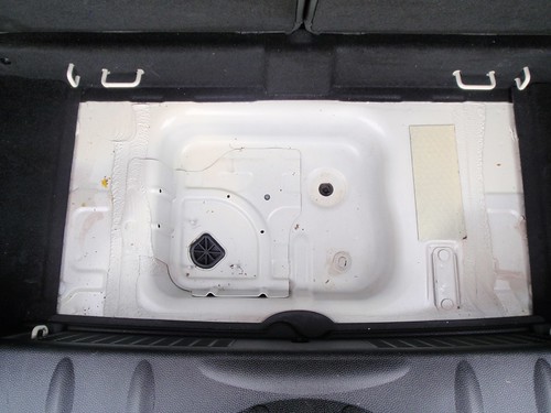
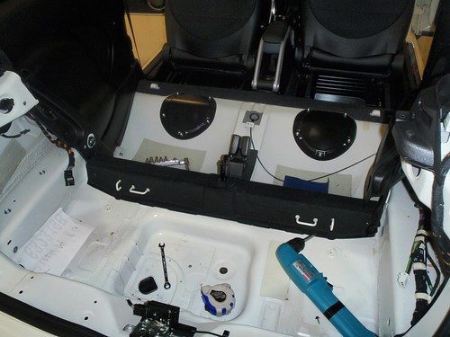
Here's the rear space I had to work with:
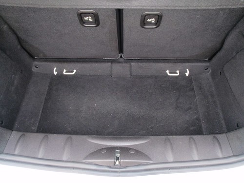
I removed the rear panel that covers the jack and pulled out the foam holder. I put the jack and tire tools in a small canvas bag that I take with me when traveling. The tow hook is now stashed in the glove box.
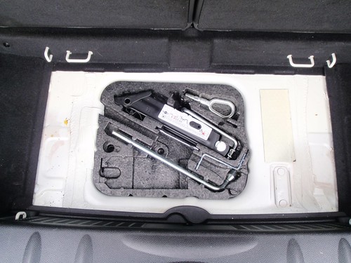
Note the small strip of sound deadening material on the right side in the well in the photo below. I'm sure that does a lot!
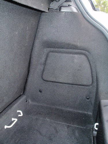
There are also the two small spaces on the left and right sides in the rear that can be used. Behind the left side is the factory HiFi amp, an emergency gas cap release and access to the rear tail lamp bulbs.
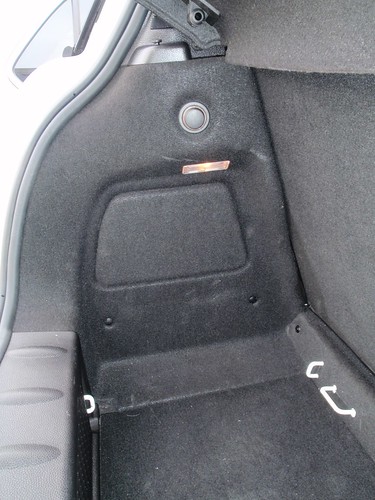
The right side is pretty open behind the fabric covered panel.
I took careful measurements of the space and then laid it out on the computer to see what would fit. I had roughly guessed that everything would fit, but this really helped me visualize it. I was also able to confirm the volume needed for the sub and estimate how tall the total enclosure would be. I was hoping that it wouldn't extend much above the rear threshold.
The JL 13TW-5 sub is a shallow mount design and does best in a sealed enclosure of about 0.81 cubic feet. Just perfect for this application.
Here are pics of the designs I created:
View from above:
I laid it all out to scale so that I could confirm dimensions. I calculated the volume of the space, adjusting the height until it ended up being 0.808 cubic feet - nearly perfect! The sub space includes the well in the floor plus a rectangular space plus a little more around the sub itself. The amps are located outside the enclosure, but recessed so they don't protrude above the sub's trim ring.
View from the side:
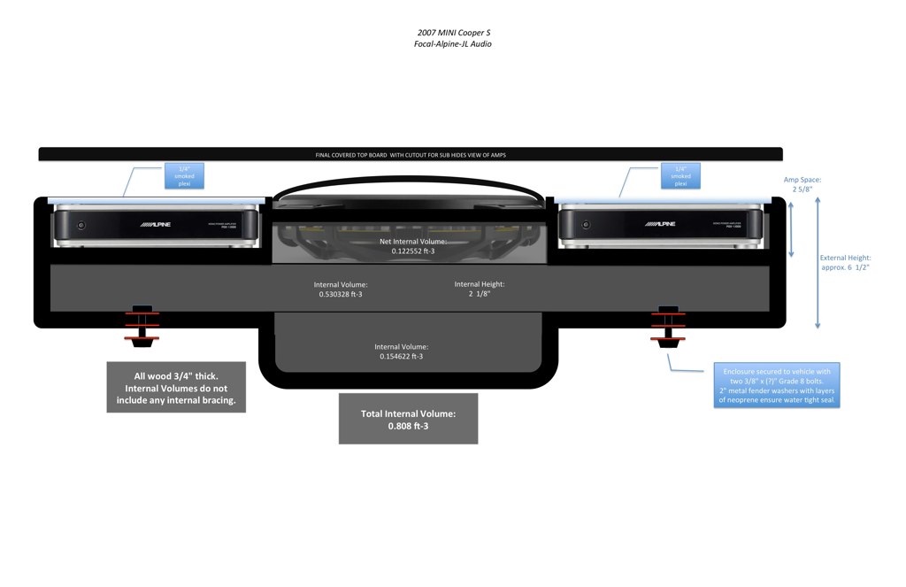
Since I plan to occasionally track and autocross the car, I wanted the whole enclosure, including the amps to be removable. To do so, and to keep the enclosure solidly mounted, I designed in two bolts that run from the interior of the enclosure down through the floor of the car. They are weather sealed to keep moisture out and are air tight.
To keep the amps out of sight, I had planned to just use a fabric covered "beauty board" that would lay over the top (as shown above), but leave the subwoofer grill open to the car.
With the round sub grill in the center of the rear, I decided to try to bring in the MINI emblem into the design.
Here's a picture that I made. Imagine the sub grill being the black circle in the center with the MINI lettering:

Dismantling starts tomorrow...
One of the first things I did after deciding to upgrade the audio system was to try to figure out how much space I had to work with. I knew that in order to keep it "stealth" I didn't want a huge sub box and I also wanted to retain as much rear space as possible.
Here's the rear space I had to work with:
I removed the rear panel that covers the jack and pulled out the foam holder. I put the jack and tire tools in a small canvas bag that I take with me when traveling. The tow hook is now stashed in the glove box.
Note the small strip of sound deadening material on the right side in the well in the photo below. I'm sure that does a lot!
There are also the two small spaces on the left and right sides in the rear that can be used. Behind the left side is the factory HiFi amp, an emergency gas cap release and access to the rear tail lamp bulbs.
The right side is pretty open behind the fabric covered panel.
I took careful measurements of the space and then laid it out on the computer to see what would fit. I had roughly guessed that everything would fit, but this really helped me visualize it. I was also able to confirm the volume needed for the sub and estimate how tall the total enclosure would be. I was hoping that it wouldn't extend much above the rear threshold.
The JL 13TW-5 sub is a shallow mount design and does best in a sealed enclosure of about 0.81 cubic feet. Just perfect for this application.
Here are pics of the designs I created:
View from above:
I laid it all out to scale so that I could confirm dimensions. I calculated the volume of the space, adjusting the height until it ended up being 0.808 cubic feet - nearly perfect! The sub space includes the well in the floor plus a rectangular space plus a little more around the sub itself. The amps are located outside the enclosure, but recessed so they don't protrude above the sub's trim ring.
View from the side:
Since I plan to occasionally track and autocross the car, I wanted the whole enclosure, including the amps to be removable. To do so, and to keep the enclosure solidly mounted, I designed in two bolts that run from the interior of the enclosure down through the floor of the car. They are weather sealed to keep moisture out and are air tight.
To keep the amps out of sight, I had planned to just use a fabric covered "beauty board" that would lay over the top (as shown above), but leave the subwoofer grill open to the car.
With the round sub grill in the center of the rear, I decided to try to bring in the MINI emblem into the design.
Here's a picture that I made. Imagine the sub grill being the black circle in the center with the MINI lettering:
Dismantling starts tomorrow...


3rd Gear
Joined: Aug 2009
Posts: 168
Likes: 0
I am also planning to do a similar install, but have been going back and forth between the 13w5 and the 8w7. I am curious though: in the boot area where the jack and tools go, if you remove the styrofoam do you see a few screws sticking up from the bottom? How did you have your installer work around this? Cut the screws or use them as an anchor for the box?
The whole enclosure is secured to the floor with two bolts, one on either side of the well as shown in the diagram above.
Door Disassembly and Sound Deadening
Again, I have to thank the previous thread authors for the excellent detailed instructions on dismantling the doors (and the important warning about the rear view mirror switch!)
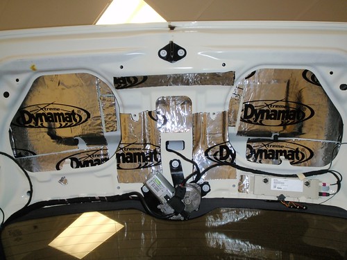
Here's the driver-side door dismantled
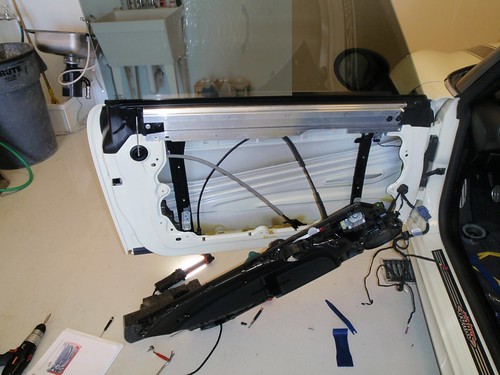
From previous car audio builds, I learned the importance of sound deadening. It's quite amazing what it can do - it also turns the normal sound of a lightweight MINI door closing to something more akin to its BMW parent, a good solid sound and feel.
Here we start the application of Dynamat Xtreme:
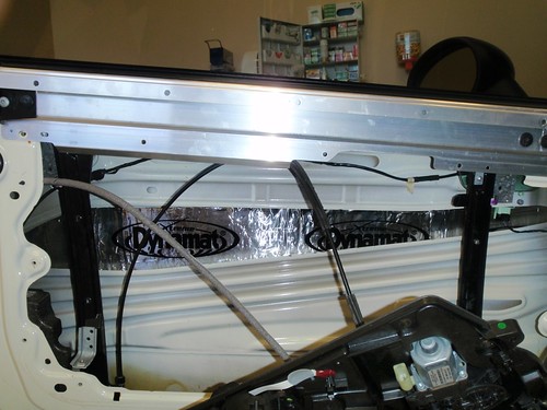
Dynamat complete (for this door)
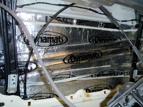
Inside each door there is a small piece of closed cell foam tucked inside. It may be used for some impact absorption, but it's so small and near the bottom that I doubt it would help much in an accident. We removed them to make room for the Dynamat.
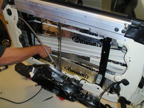
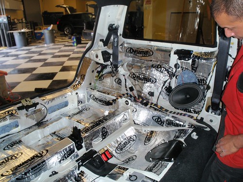
After the Dynamat we put in some Black Hole tiles. They are a multi-layer sound dampener. They also help to break up the sound waves that are driven from behind the drivers into the door cavity.
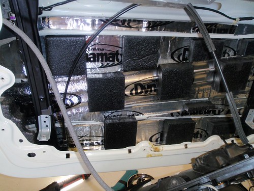
They are about 1 1/2" thick and have a self-adhesive backing. After the door was reassembled, we tested the window mechanism and had to go back in to shave down a couple pieces that were touching the glass when it was down.
Since I wanted to go with a two-way speaker rather than the three-way that the MINI HiFi uses, we simply disconnected the small midrange by the door handle.
Reassembly
Front Speaker Wiring - Although we had run new 12ga speaker wire from the amps in the back up to the front, we decided NOT to try to run it into the doors. I know, that's not in line with the level of quality I was aiming for, but MINI just doesn't give you any space to feed 12ga through their Molex-type connectors. Instead we connected just inside the cabin by the door and then used the stock wire through the door, probably 16-18ga, and then switched back to the 12ga for the last 12" or so.
There really wasn't much room in the doors for the crossover (and they're not too easy to adjust once the door is closed back up) so we located them in the rear on the left side behind the panels. This meant that we had two runs of 12ga for each side of the front speakers - one for the woofer and one for the tweeter.
Woofer Installation
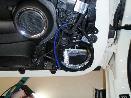
The Focal 165K2P woofer fit very nicely in the space at the bottom of the door.
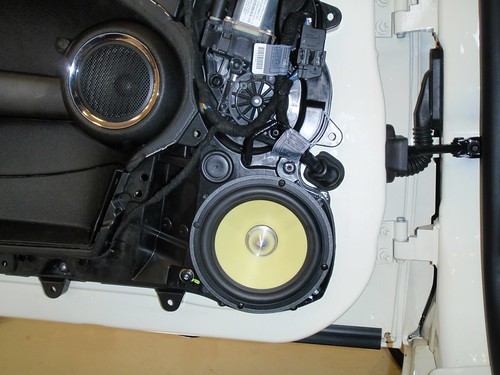
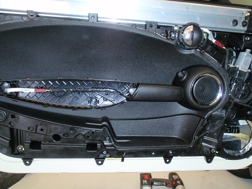
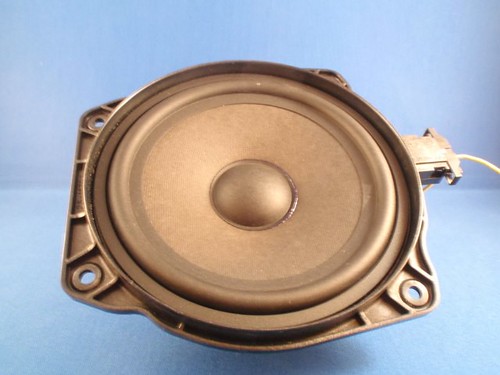
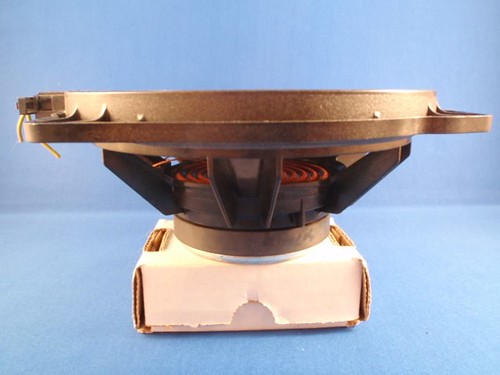
Here's what the stock HiFi woofer looks like:
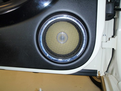
The new driver fit beautifully and looks a lot better. (Excuse the smudges on the chrome trim ring.) The flash from the camera really lights up the yellow cone, especially when looking straight at it. When in the car normally, the driver is hardly noticeable.
A-Pillar Tweeter Replacement
The A-Pillar covers are quite easy to remove (again, thanks to everyone who have gone before me!) The blue and blue/wht wires normally come from the door, but we went with new wire from the crossover in the rear.
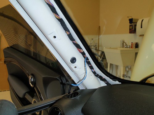
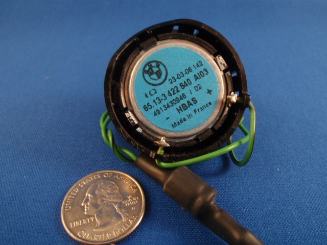
Here's the stock tweeter that came out:
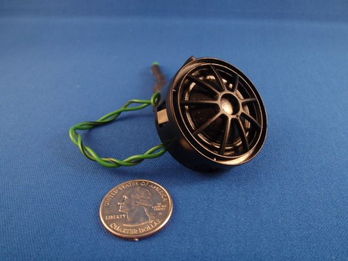
The lump under the heat shrink is a small capacitor that is used as a crossover filter for the stock tweeter.
The Focal tweeter was a little bigger, but fortunately the tweeter pod had plenty of room inside. A little adhesive glue was used to hold it in place at the proper angle.
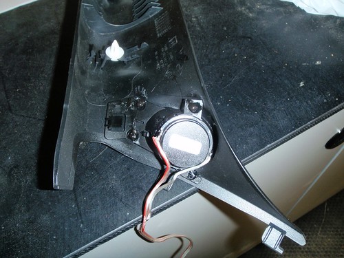
The passenger side door was done the same way.
Next up, ripping out the interior...
Again, I have to thank the previous thread authors for the excellent detailed instructions on dismantling the doors (and the important warning about the rear view mirror switch!)
Here's the driver-side door dismantled
From previous car audio builds, I learned the importance of sound deadening. It's quite amazing what it can do - it also turns the normal sound of a lightweight MINI door closing to something more akin to its BMW parent, a good solid sound and feel.
Here we start the application of Dynamat Xtreme:
Dynamat complete (for this door)
Inside each door there is a small piece of closed cell foam tucked inside. It may be used for some impact absorption, but it's so small and near the bottom that I doubt it would help much in an accident. We removed them to make room for the Dynamat.
After the Dynamat we put in some Black Hole tiles. They are a multi-layer sound dampener. They also help to break up the sound waves that are driven from behind the drivers into the door cavity.
They are about 1 1/2" thick and have a self-adhesive backing. After the door was reassembled, we tested the window mechanism and had to go back in to shave down a couple pieces that were touching the glass when it was down.
Since I wanted to go with a two-way speaker rather than the three-way that the MINI HiFi uses, we simply disconnected the small midrange by the door handle.
Reassembly
Front Speaker Wiring - Although we had run new 12ga speaker wire from the amps in the back up to the front, we decided NOT to try to run it into the doors. I know, that's not in line with the level of quality I was aiming for, but MINI just doesn't give you any space to feed 12ga through their Molex-type connectors. Instead we connected just inside the cabin by the door and then used the stock wire through the door, probably 16-18ga, and then switched back to the 12ga for the last 12" or so.
There really wasn't much room in the doors for the crossover (and they're not too easy to adjust once the door is closed back up) so we located them in the rear on the left side behind the panels. This meant that we had two runs of 12ga for each side of the front speakers - one for the woofer and one for the tweeter.
Woofer Installation
The Focal 165K2P woofer fit very nicely in the space at the bottom of the door.
Here's what the stock HiFi woofer looks like:
The new driver fit beautifully and looks a lot better. (Excuse the smudges on the chrome trim ring.) The flash from the camera really lights up the yellow cone, especially when looking straight at it. When in the car normally, the driver is hardly noticeable.
A-Pillar Tweeter Replacement
The A-Pillar covers are quite easy to remove (again, thanks to everyone who have gone before me!) The blue and blue/wht wires normally come from the door, but we went with new wire from the crossover in the rear.
Here's the stock tweeter that came out:
The lump under the heat shrink is a small capacitor that is used as a crossover filter for the stock tweeter.
The Focal tweeter was a little bigger, but fortunately the tweeter pod had plenty of room inside. A little adhesive glue was used to hold it in place at the proper angle.
The passenger side door was done the same way.
Next up, ripping out the interior...
4th Gear
Joined: Dec 2009
Posts: 403
Likes: 3
From: Toronto, Ontario, Canada
Nice work so far........... those black tiles to break up the back wave in the doors............. where did you get those from??
Looking forward to the rest of the updates. Come spring I'm going to gut my '08 Clubman S for such an upgrade as well.
Looking forward to the rest of the updates. Come spring I'm going to gut my '08 Clubman S for such an upgrade as well.
Trending Topics

2nd Gear
Joined: Mar 2007
Posts: 57
Likes: 0
Best Practices
I'm about to embark on my upgrade as well and this will be extremely useful!! - THANKS
I have been trying to compile a list of "Best Practices" from the various threads in order to inform the installers as best as possible. I don't want to hijack this thread but maybe we can compile a list and when complete move it out to a sticky. Here is what I have so far.
Breakdown Comments
- Front Door / Side view Mirror ... Be careful with the side mirror controller on the driver's door when you take the panel off. It has a lot of little parts that can drop out and be lost. Make sure you see exactly how the parts all go together so you can reassemble it, should parts drop out.
- Puddle Lights ...You will have to disconnect the puddle lights when you take the door panels off. It will be obvious, but be aware that a wire will be connected from the panel to the door at the bottom when you pull the panel off.
Install Comments
?
Wiring Comments
- X9331 Connector .... Create an X9331 connector so you can reconnect the stock amp in order to get dealer software upgrades in the future
- Amp Turn On ... Use the cig ligher circuit for your amp turn-on. Tap it in the rear or front console. Don't use an Add-A-Circuit because it is a 20 amp circuit, and they don't make an Add-A-Circuit that can handle that much amperage
Reassemble Comments
- Seats ... Reconnect seats before starting engine in order to avoid CEL seat default

1st Gear
Joined: Aug 2009
Posts: 21
Likes: 0
I used to have those same speakers in my jetta. They sound really good but the tweeters were too bright for me. I had them with -6db attenuation. You may want to test them first with the doors closed to check brightness. I failed to do that and had to remove the crossovers after i already had finished the installation.
I got it from the installer. You can do a google search for "blackhole 5" and find a few places that sell it. It's often used by diy speakerbuilders.
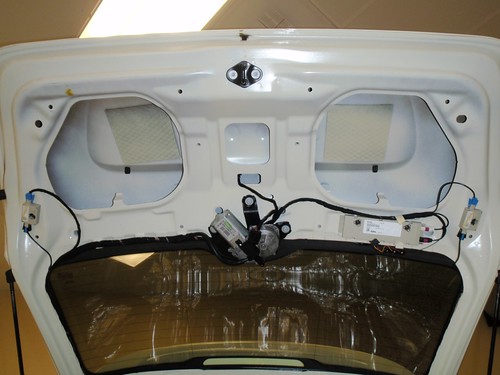
Dismantling the Rear Interior
First remove the rear trim panels starting with the rear threshold and moving to the left side exposing the factory audio amp.
The amp is connected with a large multi-pin connector that includes the inputs from the stock headunit, outputs going to the speaker, power-in, turn-on signal, and computer controls.
IMPORTANT:
DO NOT CUT OFF THIS LARGE BLACK CONNECTOR! If you use this as the source for your low level inputs, only cut the wires you need (We just used the front left and right low-level inputs since we were not connecting the rear speakers. (Sorry, I don't have the pin and wire color specs in front of me, but they are available here on NAM.)
If you ever want to update the car's software, the factory amp MUST be reconnected. The dealer software that updates the car first checks for the presence of all control units - the factory audio amp being one of them (go figure!).
Why would you want/need to update your car's software? Well, for example I installed the JCW Sport Brake Kit after upgrading the audio system. Because of the different size calipers and rotors in this kit, the DSC and ABS computers have to be adjusted to compensate for the change. This is done with a software update!
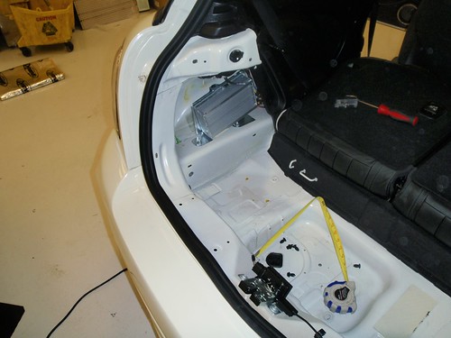
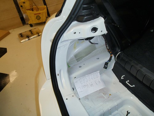
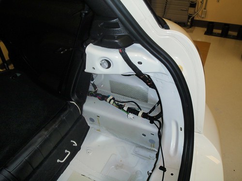
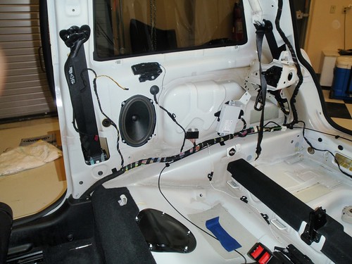
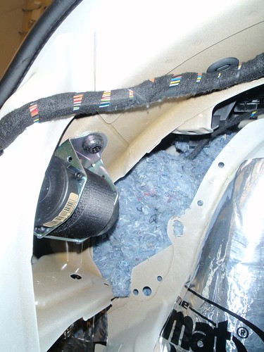
Here is the right side of the rear showing the rear wiring harness that goes to the tail lamps, rear fog lights, PDC, etc. The white plug that you can see connects to the PDC module if you have that option (my car does not).
Removal of the bottom of the backseat is quite easy. Remove the plastic trim pieces that provide access to the child seat hooks, and then lift straight up from the front. There are two spring clips that hold the front down that you can see in the photo.
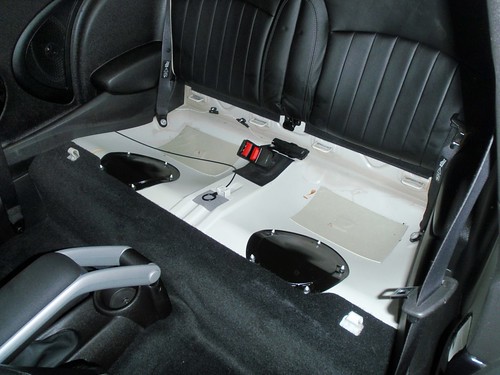
Note the two huge squares of factory sound dampening beneath the rear seats!
The rear seatback can then be removed.
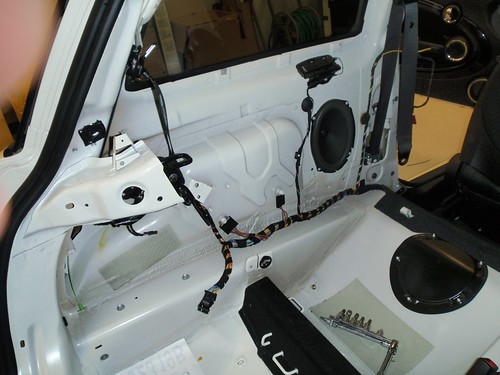
After that the rear side panels can be removed, exposing the rear speakers.
Left side:
Right side:
Application of Dynamat Xtreme next.....
First remove the rear trim panels starting with the rear threshold and moving to the left side exposing the factory audio amp.
The amp is connected with a large multi-pin connector that includes the inputs from the stock headunit, outputs going to the speaker, power-in, turn-on signal, and computer controls.
IMPORTANT:
DO NOT CUT OFF THIS LARGE BLACK CONNECTOR! If you use this as the source for your low level inputs, only cut the wires you need (We just used the front left and right low-level inputs since we were not connecting the rear speakers. (Sorry, I don't have the pin and wire color specs in front of me, but they are available here on NAM.)
If you ever want to update the car's software, the factory amp MUST be reconnected. The dealer software that updates the car first checks for the presence of all control units - the factory audio amp being one of them (go figure!).
Why would you want/need to update your car's software? Well, for example I installed the JCW Sport Brake Kit after upgrading the audio system. Because of the different size calipers and rotors in this kit, the DSC and ABS computers have to be adjusted to compensate for the change. This is done with a software update!
Here is the right side of the rear showing the rear wiring harness that goes to the tail lamps, rear fog lights, PDC, etc. The white plug that you can see connects to the PDC module if you have that option (my car does not).
Removal of the bottom of the backseat is quite easy. Remove the plastic trim pieces that provide access to the child seat hooks, and then lift straight up from the front. There are two spring clips that hold the front down that you can see in the photo.
Note the two huge squares of factory sound dampening beneath the rear seats!
The rear seatback can then be removed.
After that the rear side panels can be removed, exposing the rear speakers.
Left side:
Right side:
Application of Dynamat Xtreme next.....
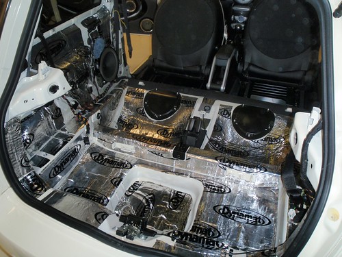
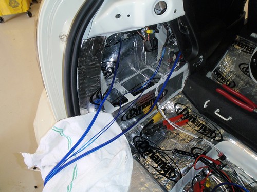
Installation of Sound Damping in Rear
When installing damping sheets, always start with the biggest areas first then cut the scrap pieces to fit the medium and then cover the small areas last.
Dynamat Xtreme comes in large bulk packs that cover 36sqft. At 0.45lbs/sqft one bulk pack adds about 16lbs to the car, so I don't suggest using it if you are really concerned about weight. I easily used one bulk pack and could have used more, but (in my opinion) after you cover about 80% you start to hit diminishing returns in benefits to improving the sound versus the time/cost to install. Some hardcore car audio competitors will put multiple layers and hundreds of pounds of damping in their cars to eek out that last little bit of improvement.
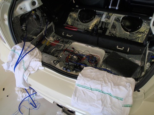
Now for some pics.
Here's where we left off with all of the rear trim and back seats removed.
Behind the rear speaker is a fairly large open space that you can see here.
The installers stuffed some acoustical batting back in that space and several others.
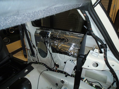
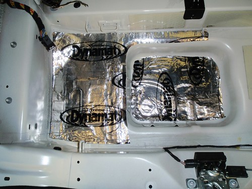
Right rear side covered. To get the best performance from the damping sheets, after applying them using the peel and stick backing, you use a small roller to press it firmly against the sheet metal and roll out any air bubbles.

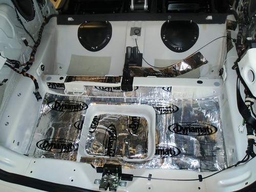
Here's the rear well. After pulling out the carpeting and remeasuring the space, it turns out that it is not exactly centered between the two sides. We had to adjust the sub enclosure design slightly to compensate.
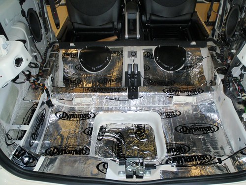
Into the area beneath the rear seats and back against the rear threshold.
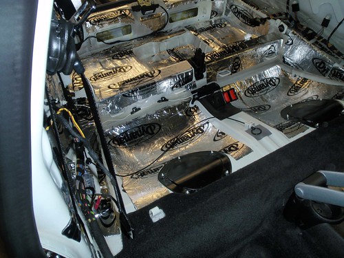
And around to the left side.
When installing damping sheets, always start with the biggest areas first then cut the scrap pieces to fit the medium and then cover the small areas last.
Dynamat Xtreme comes in large bulk packs that cover 36sqft. At 0.45lbs/sqft one bulk pack adds about 16lbs to the car, so I don't suggest using it if you are really concerned about weight. I easily used one bulk pack and could have used more, but (in my opinion) after you cover about 80% you start to hit diminishing returns in benefits to improving the sound versus the time/cost to install. Some hardcore car audio competitors will put multiple layers and hundreds of pounds of damping in their cars to eek out that last little bit of improvement.
Now for some pics.
Here's where we left off with all of the rear trim and back seats removed.
Behind the rear speaker is a fairly large open space that you can see here.
The installers stuffed some acoustical batting back in that space and several others.
Right rear side covered. To get the best performance from the damping sheets, after applying them using the peel and stick backing, you use a small roller to press it firmly against the sheet metal and roll out any air bubbles.
Here's the rear well. After pulling out the carpeting and remeasuring the space, it turns out that it is not exactly centered between the two sides. We had to adjust the sub enclosure design slightly to compensate.
Into the area beneath the rear seats and back against the rear threshold.
And around to the left side.
Oh yeah, we forgot about this...
Open it up. Notice two more factory damping squares.
A bit better now
The rear speakers are not going to be used, but we left the speaker wires connected. They are also still connected at the amplifier plug making it easy to reconnect if necessary. Note the batting stuffed into the cavity behind the speaker.
Reassembly. Say "Hi" Johnny.
Wiring Up the Power
Not a lot of pictures here.
A single 2-gauge power wire was run from the battery to a 100amp fuse inside the battery compartment. It is then routed through the nice rubber grommet that MINI provides at the firewall next to the battery, and then into the car above the fuse box at the right side of the passenger side footwell. Once inside it follows along with the other power wiring on the passenger side under the trim toward the rear of the car.
A power/ground distribution block was placed behind the small removable panel on the right in the rear. There power is split into two 4-gauge runs, one to each amplifier.
(Not shown) 4-gauge ground wires from each amplifier lead back to the distribution block where they are combined into a single 2-gauge wire. This in then connected directly to the car body. (Another option is to run the ground wire all the way back to negative terminal of the battery. There are pros and cons to each approach.)
Audio Wiring
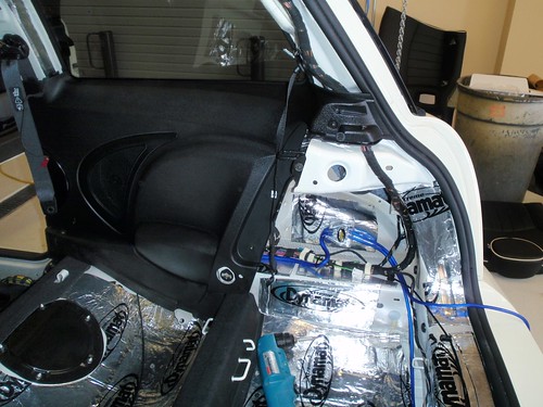
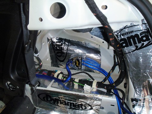
All audio wiring is run on the left side of the car to keep it away from the high current power lines.
Here you can see the speaker cables (the thicker blue cables) coming from the front and the thinner blue turn-on wires that are coming from the turn-on wire in the plug. You can also see the front speaker wires (the white twisted pairs) coming from the factory headunit that will connect to the Alpine PXE-H650.
The Alpine processor will be placed behind the left side removable panel. Since this area is not flat, a small MDF panel was covered in black carpet and attached to the car and then the Alpine was mounted on that.
Although I had provided the pin-out diagrams and wire color diagrams provided by fellow NAMers, the installers tested everything to make sure that they were accurate. With annual and even mid-year model changes, it's better to validate rather than assume!
Next up...Building the Enclosure
Building the Enclosure
One of my requests for this build was to still be able to get to each of the white metal hooks that are in the rear well and for the enclosure to be removable for track/autocross days. This forced the enclosure to be slightly less "fitted" than it could have been, but after being covered in black vinyle that matches the texture of the trim panels, it's hardly noticeable.
As I mentioned before, the well for the tool kit is NOT centered between the two sides of the car, so some minor adjustments had to be made. You can see this in the next picture.
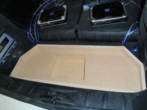
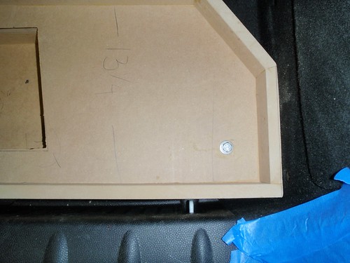
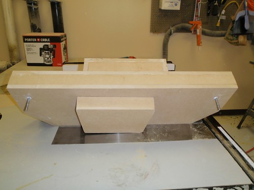
Here is the bottom of the enclosure being test fit.
3/4" MDF was used to build the enclosure.
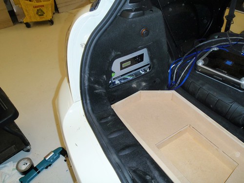
Here is the base with side walls added. The two PDX amps were connected and tested prior to installation.
You can see that the Alpine PXE-H650 is now installed behind the left side access panel. Sometime shortly after installation I had to change a turn signal bulb on that side. In order to get back there I had to remove the Alpine unit and then the board it was attached to. Not difficult, but just an inconvenience.
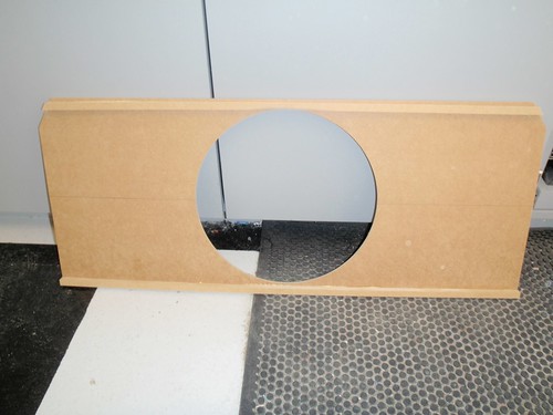
The bottom section of the base was completed, and a hole was cut out to open it to the smaller top section where the subwoofer will be mounted.
Remember, this was the original enclosure design:
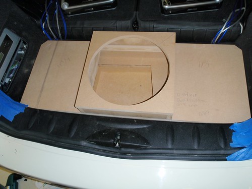
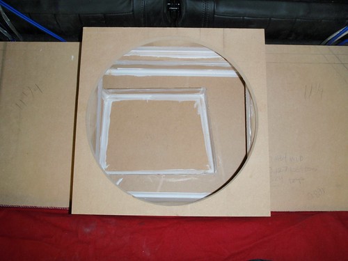
Here you can see the top section and the 13.5" diameter hole for the JL Audio 13TW5-3 sub.
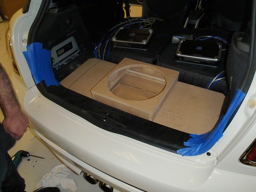
See how the hole for the tool well does not line up with the upper sub mounting enclosure? Fortunately, there was no overlap and the top section could still be centered on the board.
In order to secure the entire enclosure to the car, two bolts were run from inside the bottom floor of the enclosure through the floor of the car and attached with locking nuts underneath the car. All points of contact were weather sealed to prevent rust and any chance of possible water intrusion.
The total cabinet volume for the subwoofer includes the small box on top PLUS the full width (but short height) volume below PLUS a bit more volume where the tool tray used to be. I had estimated that the volume would be 0.808 cubic feet. Actual volume ended up at 0.81 cubic feet. The optimal sealed volume for this particular subwoofer is 0.80 cubic feet. Just about perfect!
Additional batting was added to the enclosure to dampen some of the back waves from the sub, tightening the sound and extending the low frequencies slightly.
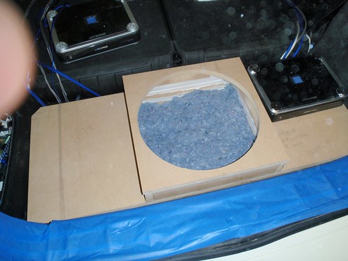
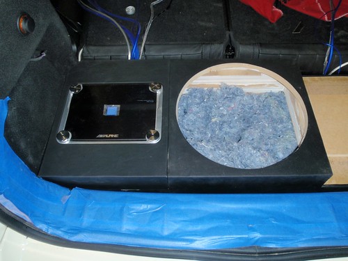
Here the JL sub is being test fit in the enclosure with the PDX1.600 sitting next to it.
The left side with the PDX-4.150 checking the fit of the amp surround. This will be removable in order to gain access to the wiring and controls.
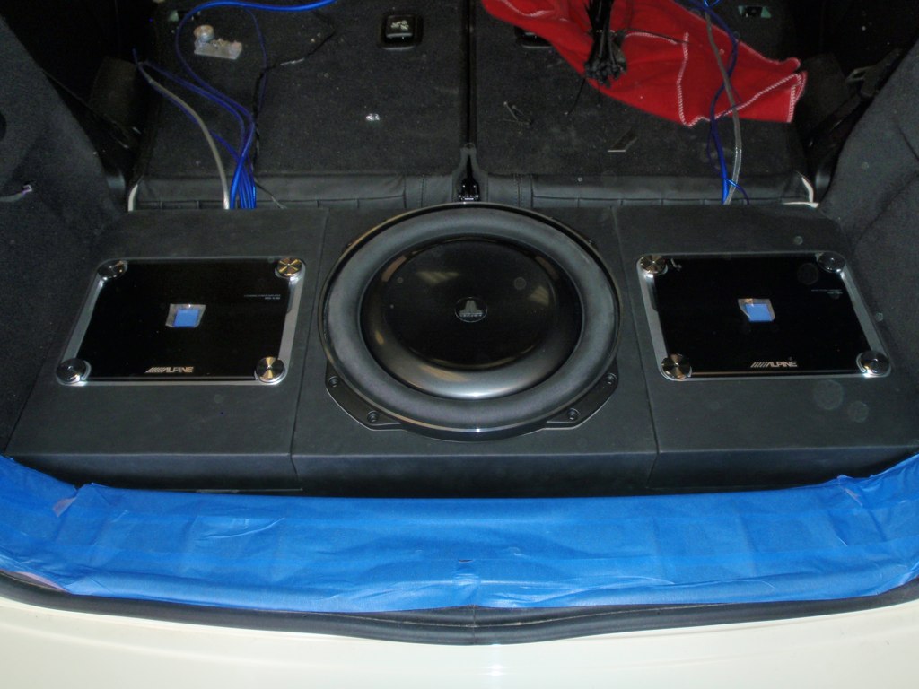
With both amp surrounds and subwoofer. Now it's starting to look like my original design!
One change that we had to make from my original design was that we had to forego the smoked plexiglass covers over the amps. Although they are Class D amps and run cooler than most, they do still give off some heat. There was some concern that it would be TOO sealed and not allow the amplifiers to vent any heat. It also would have increased the entire height of the enclosure, something I wanted to try to keep to a minimum.
Main enclosure back out of the car. Time to stuff and seal the enclosure and then wrap the box in a nice vinyl to make it look good. Again, notice that the portion of the enclosure that fills the tool storage space is slightly left of center.
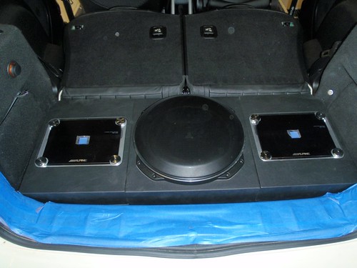
Here's the left piece and center box covered in vinyl. I really like the flush mounting of the amps. The four round circles on the amp stick up only slightly above the level of the surround and the amp cover fits perfectly snug around all sides.
Quite a snug fit after applying the vinyl, but this is what I had envisioned. It's tough to tell the height of the box versus the trunk threshold, but it's only about an inch or two higher. It comes up to just below the bottoms of the left and right access panels. Not bad at all.
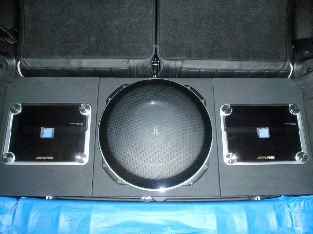
Same picture but with the JL subwoofer grill in place. I was initially worried that the grill might dent easily since it will be sticking out above the enclosure and the beauty board, but it is VERY sturdy. This is no flimsy grill!
Another shot from above. Notice that you can actually still access all of the white metal loops in the cargo area if necessary. You can see the two between the enclosure and the blue tape. Also, the vinyl we chose is a great color and texture match for the car's leather interior.
Next we'll build the beauty board that will hide the amps...
One of my requests for this build was to still be able to get to each of the white metal hooks that are in the rear well and for the enclosure to be removable for track/autocross days. This forced the enclosure to be slightly less "fitted" than it could have been, but after being covered in black vinyle that matches the texture of the trim panels, it's hardly noticeable.
As I mentioned before, the well for the tool kit is NOT centered between the two sides of the car, so some minor adjustments had to be made. You can see this in the next picture.
Here is the bottom of the enclosure being test fit.
3/4" MDF was used to build the enclosure.
Here is the base with side walls added. The two PDX amps were connected and tested prior to installation.
You can see that the Alpine PXE-H650 is now installed behind the left side access panel. Sometime shortly after installation I had to change a turn signal bulb on that side. In order to get back there I had to remove the Alpine unit and then the board it was attached to. Not difficult, but just an inconvenience.
The bottom section of the base was completed, and a hole was cut out to open it to the smaller top section where the subwoofer will be mounted.
Remember, this was the original enclosure design:
Here you can see the top section and the 13.5" diameter hole for the JL Audio 13TW5-3 sub.
See how the hole for the tool well does not line up with the upper sub mounting enclosure? Fortunately, there was no overlap and the top section could still be centered on the board.
In order to secure the entire enclosure to the car, two bolts were run from inside the bottom floor of the enclosure through the floor of the car and attached with locking nuts underneath the car. All points of contact were weather sealed to prevent rust and any chance of possible water intrusion.
The total cabinet volume for the subwoofer includes the small box on top PLUS the full width (but short height) volume below PLUS a bit more volume where the tool tray used to be. I had estimated that the volume would be 0.808 cubic feet. Actual volume ended up at 0.81 cubic feet. The optimal sealed volume for this particular subwoofer is 0.80 cubic feet. Just about perfect!
Additional batting was added to the enclosure to dampen some of the back waves from the sub, tightening the sound and extending the low frequencies slightly.
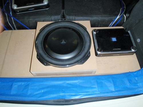
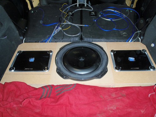
Here the JL sub is being test fit in the enclosure with the PDX1.600 sitting next to it.
The left side with the PDX-4.150 checking the fit of the amp surround. This will be removable in order to gain access to the wiring and controls.
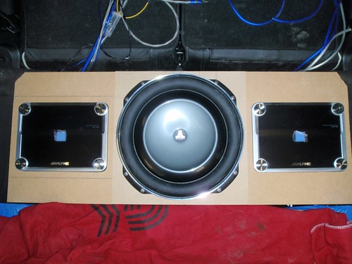
With both amp surrounds and subwoofer. Now it's starting to look like my original design!
One change that we had to make from my original design was that we had to forego the smoked plexiglass covers over the amps. Although they are Class D amps and run cooler than most, they do still give off some heat. There was some concern that it would be TOO sealed and not allow the amplifiers to vent any heat. It also would have increased the entire height of the enclosure, something I wanted to try to keep to a minimum.
Main enclosure back out of the car. Time to stuff and seal the enclosure and then wrap the box in a nice vinyl to make it look good. Again, notice that the portion of the enclosure that fills the tool storage space is slightly left of center.
Here's the left piece and center box covered in vinyl. I really like the flush mounting of the amps. The four round circles on the amp stick up only slightly above the level of the surround and the amp cover fits perfectly snug around all sides.
Quite a snug fit after applying the vinyl, but this is what I had envisioned. It's tough to tell the height of the box versus the trunk threshold, but it's only about an inch or two higher. It comes up to just below the bottoms of the left and right access panels. Not bad at all.
Same picture but with the JL subwoofer grill in place. I was initially worried that the grill might dent easily since it will be sticking out above the enclosure and the beauty board, but it is VERY sturdy. This is no flimsy grill!
Another shot from above. Notice that you can actually still access all of the white metal loops in the cargo area if necessary. You can see the two between the enclosure and the blue tape. Also, the vinyl we chose is a great color and texture match for the car's leather interior.
Next we'll build the beauty board that will hide the amps...
 How does the 13w5 sound? paired with the rest of your setup?


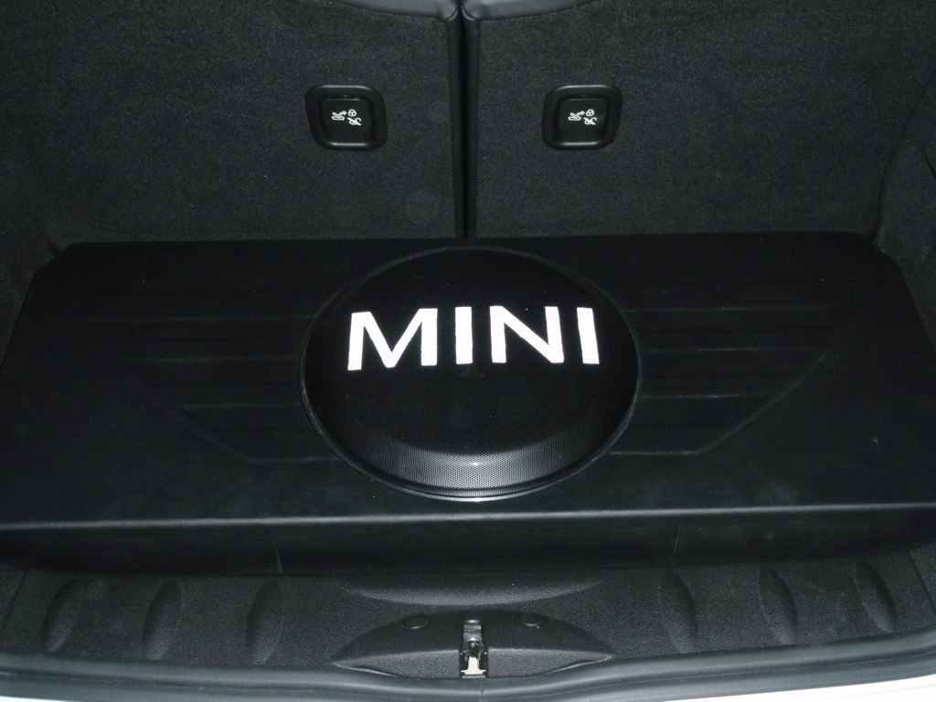
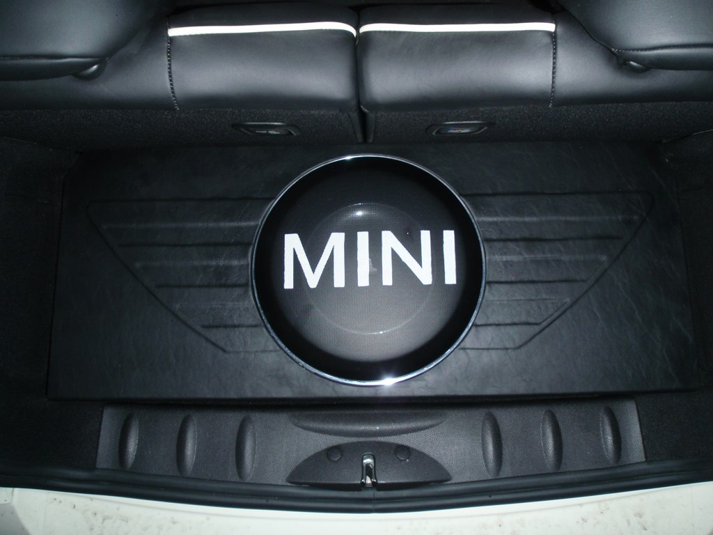
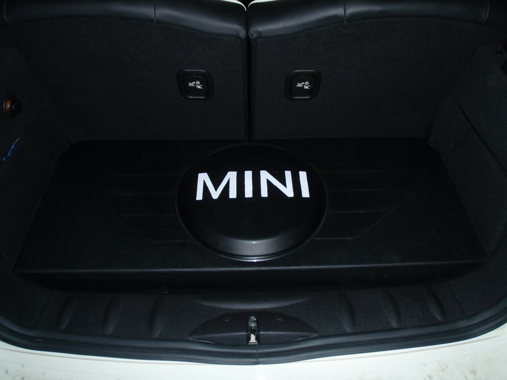
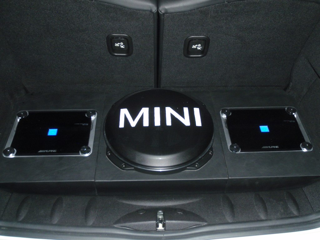
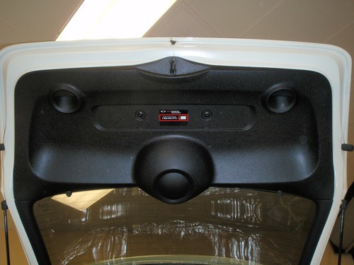
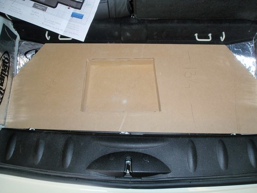
Finishing Touches
Originally I had planned to just do a plain carpeted "beauty board" to cover/protect the amps. After the install got started, I had an idea for something a bit more "MINI".
Here's the original board. The board lays over the amps with the sub's grill sticking up through the center of the board.
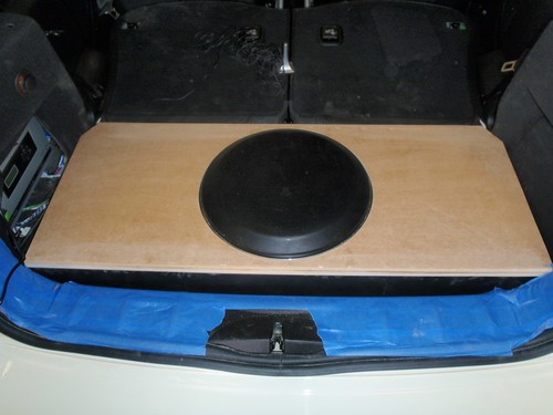
It was a tight fit, but the raised edges that hold the board above the amps will also provide some reinforcement.
Now for the fun part!
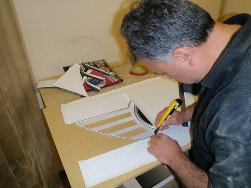
I found an image of the MINI winged logo and enlarged it in Photoshop until the round center of the logo fit the actual diameter of the subwoofer ring. I then had Kinko's print it up on their big printer to use as a template for a relief pattern. I took it over to my installers to see if they could do it.
Here Des has cut the print in half and is removing some of the sections.
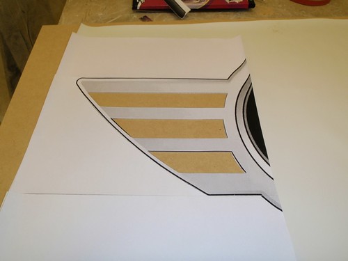
Laid out on the board, only a few changes had to made to the pattern.
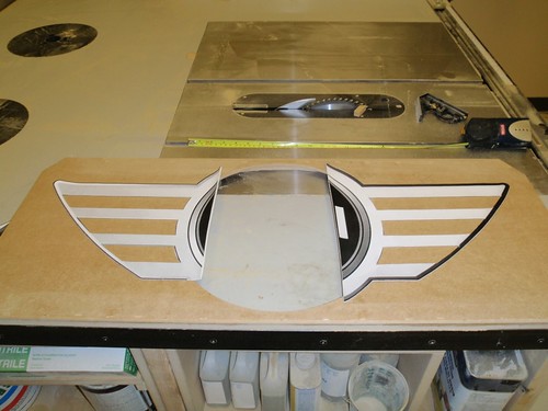
Here it is laid out over the sub.
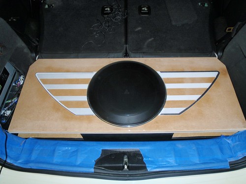
Pieces of Dynamat were used to lay down the relief, and then the board was covered in the textured vinyl.
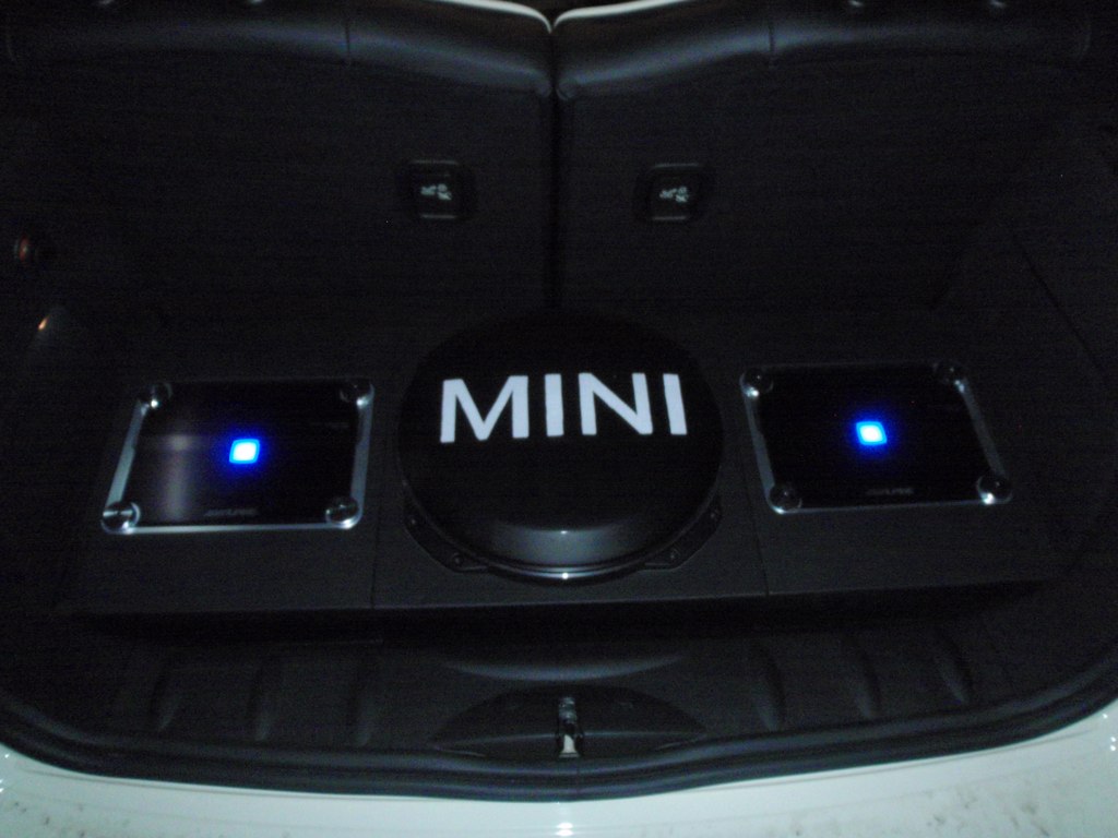
It's a nice subtle logo.
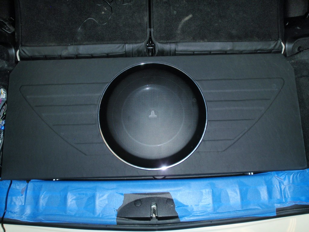
But...it's missing one thing.
I made a stencil out of cardboard and sprayed the subwoofer grill with metal primer and then several coats of enamel paint. The paint was applied lightly with each layer so that the holes in the grill didn't clog.
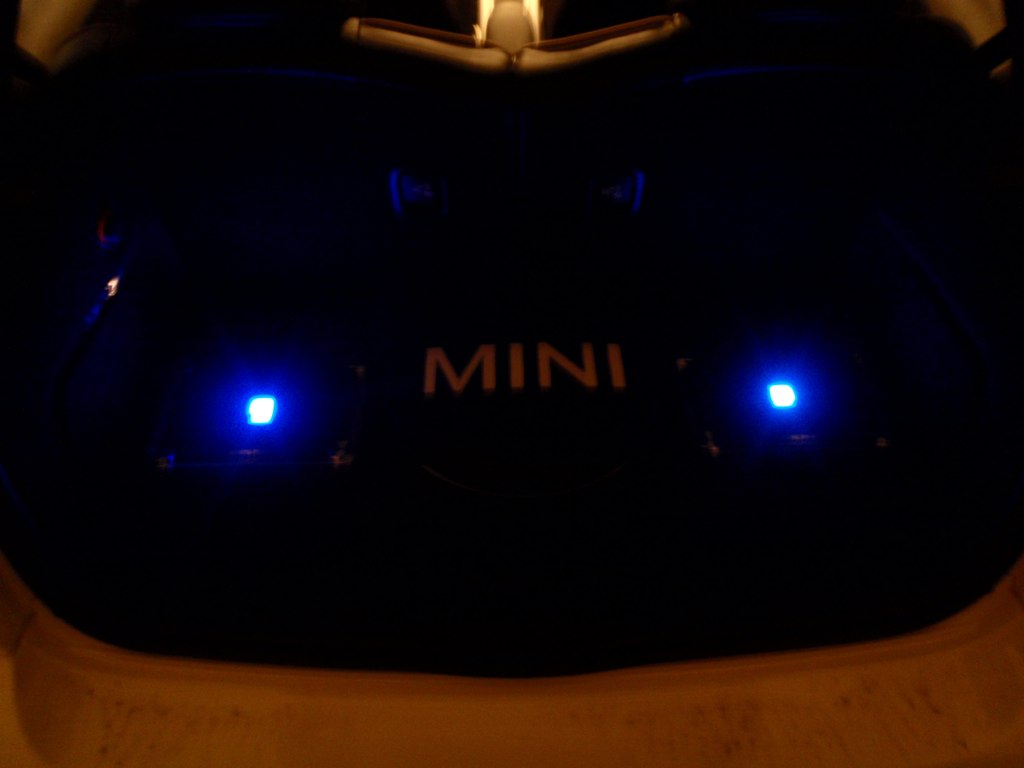
I was very satisfied with the end result...
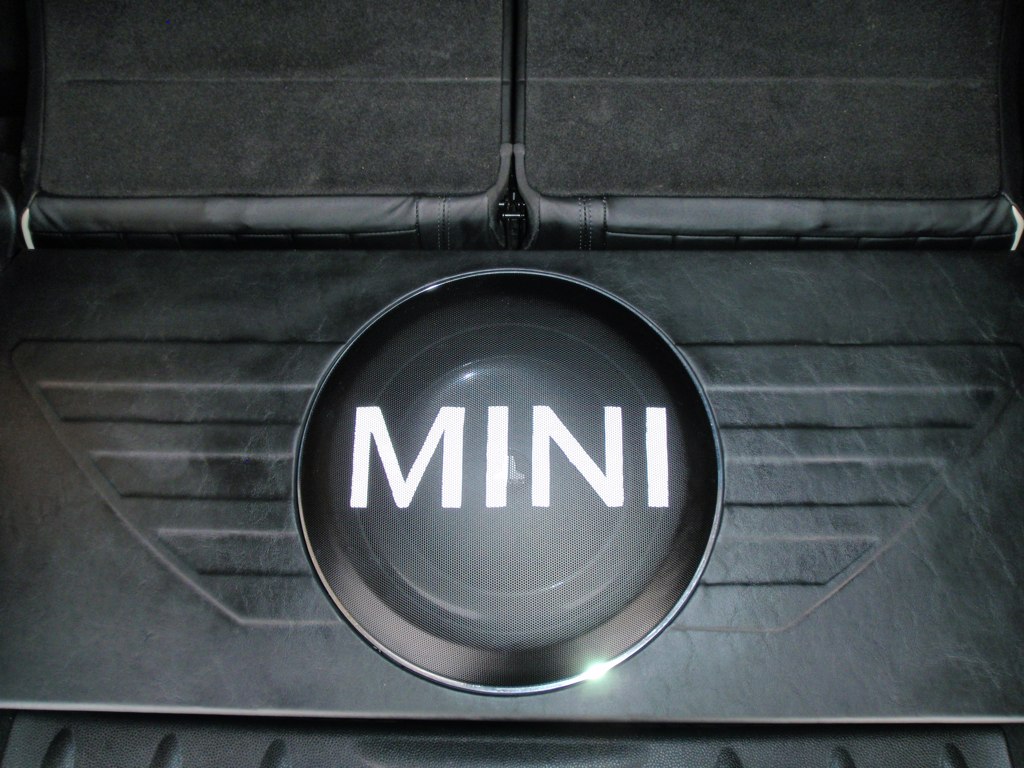
The angle of the camera makes the logo look like it's not centered, but it is.
Originally I had planned to just do a plain carpeted "beauty board" to cover/protect the amps. After the install got started, I had an idea for something a bit more "MINI".
Here's the original board. The board lays over the amps with the sub's grill sticking up through the center of the board.
It was a tight fit, but the raised edges that hold the board above the amps will also provide some reinforcement.
Now for the fun part!
I found an image of the MINI winged logo and enlarged it in Photoshop until the round center of the logo fit the actual diameter of the subwoofer ring. I then had Kinko's print it up on their big printer to use as a template for a relief pattern. I took it over to my installers to see if they could do it.
Here Des has cut the print in half and is removing some of the sections.
Laid out on the board, only a few changes had to made to the pattern.
Here it is laid out over the sub.
Pieces of Dynamat were used to lay down the relief, and then the board was covered in the textured vinyl.
It's a nice subtle logo.
But...it's missing one thing.
I made a stencil out of cardboard and sprayed the subwoofer grill with metal primer and then several coats of enamel paint. The paint was applied lightly with each layer so that the holes in the grill didn't clog.
I was very satisfied with the end result...
The angle of the camera makes the logo look like it's not centered, but it is.
I used to have those same speakers in my jetta. They sound really good but the tweeters were too bright for me. I had them with -6db attenuation. You may want to test them first with the doors closed to check brightness. I failed to do that and had to remove the crossovers after i already had finished the installation.
Because of the changes in sound after break-in, you may need to reset the crossovers, attenuation, and equalization. And that's why I prefer to put the crossovers in the rear where they are easier to access than behind the door panels.
Tom