
Drivetrain Coolingmist VC2 trunkmount install


Thread Starter
|
4th Gear
Joined: Jan 2009
Posts: 520
Likes: 0
Coolingmist VC2 trunkmount install
Hi everyone,
Ive just ordered myself the all new Coolingmist VC2 Trunkmount w/m system. With it I added:
- Solenoid Fluid Control
- 2 nozzle setup (complete with T-junctions, M1 nozzle (pre-SC), M2 nozzle (post IC)
- Stainless steel hoses (5 foot for engine bay application only)
Im planning to run the kit as follows:
[FONT=Arial]Trunkmount tank >>>>nylon water line >>>> tee>>>Solenoid >>>>Y split to each injector>>>SS hose (M1 injector to Intake Hose or Pre-SC)
>>>SS hose (M2 injector to Post-IC)
[/FONT]
Ive got no experience on w/m kits and from reading alot of threads here in NAM it still does not help me as the kit has not arrived yet.
So, Since NAM has got the most users with water/meth injection. I was wondering if you guys have installed a similar setup like this. If you have, please answer the following questions:
- Any pics on how to install the kit or a similar kit?
- Any pics of how to route the hoses from the trunk to the engine bay?
- VC2 is a progressive control unit. How does it work? Where does it connect to? TMAP? MAP? 0-5V?
- If answer to the above is MAP, where is the MAP sensor and how should I tap it?
- How does the solenoid work? Where to install it?

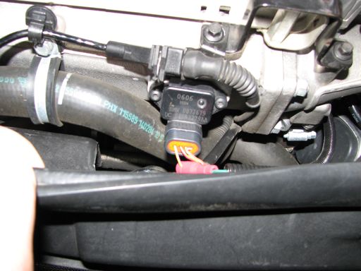
Naz - hard to tell from the docs on their site exactly what the options are - based on what you said, if it can connect to "boost line" or MAP, then the question is whether the unit comes with a separate MAP sensor to mount in the engine bay, or if there is a MAP sensor built into the controller that requires a boost/vac line to be run to it in the boot... if it's a separate MAP sensor, then you tap it into the main vacuum line on the manifold just like you would install a boost gauge. If it's an integrated MAP/boost sensor, I personally wouldn't want to run a boost line all the way to the boot; I'd run a wire instead and wire it to the OEM TMAP sensor on the front of the intake manifold. It's the purple/yellow wire on the left as you face it from the front.
Thread Starter
|
4th Gear
Joined: Jan 2009
Posts: 520
Likes: 0
These are the specs for the all new VC2 controller from Coolingmist:
-Built in 30 PSI map sensor
-Built in 0-5V input
- No computer or laptop required. Unit is fulling programmable from simple menu commands
inject based on 1 or 2 inputs.
- Small size (approx 3.5 X 3.5 inches)
- Boost is converted to 0-5V signal output
- External digital ground activated when you reach your MIN pressure (can be used for solenoid activation)
choice of blue or red 3 digit display
- Input for optional flow sensor
- Can display boost, 0-5V, Dutycycle, Flow (with flow sensor) or any 0-5V input.
0-5V multiplier
So, from this what can you tell me?
And what are the pro and cons running Boostline over TMAP or vice versa
Trending Topics
Looks like the boost/map sensor is built into the controller. So to use the built-in sensor, you'd have to run a vacuum line to wherever the controller is mounted. I know some others have done this - I believe that's what the line is that you see connected to the controller in longboard's photo above.
Personally, I think running a boost/vac line that long is just one more thing to develop a leak over time... and the long length of the line would reduce the response of the system by a small (maybe tiny?) amount since the volume of that line must be pressurized and evacuated continuously as the pressure of the car's vacuum system changes. I personally see NO downside to tapping the TMAP sensor - it's working perfectly on my car - though, given how finicky the sensor/ECU systems on these cars can be, some folks have said they feel more confident in using the vacuum/boost line approach.
This is all assuming you're mounting the controller in the boot with the tank... if the controller were going to be up front with your instruments panel, then running the vac line is no different than running one for a boost gauge...
Really a toss-up. Maybe a little more foolproof to use the vacuum line, only because then you don't have to worry about how the calibration of the controller matches the output signal of the TMAP. In my case, it was a non-issue as my controller was set to match the 2.5bar TMAP sensor.

Thread
Thread Starter
Forum
Replies
Last Post