When you click on links to various merchants on this site and make a purchase, this can result in this site earning a commission. Affiliate programs and affiliations include, but are not limited to, the eBay Partner Network.
Stock Problems/IssuesDiscussions related to warranty related issues and repairs, or other problems with the OEM parts and software for MINI Clubman (R55), Cooper and Cooper S(R56), and Cabrio (R57).
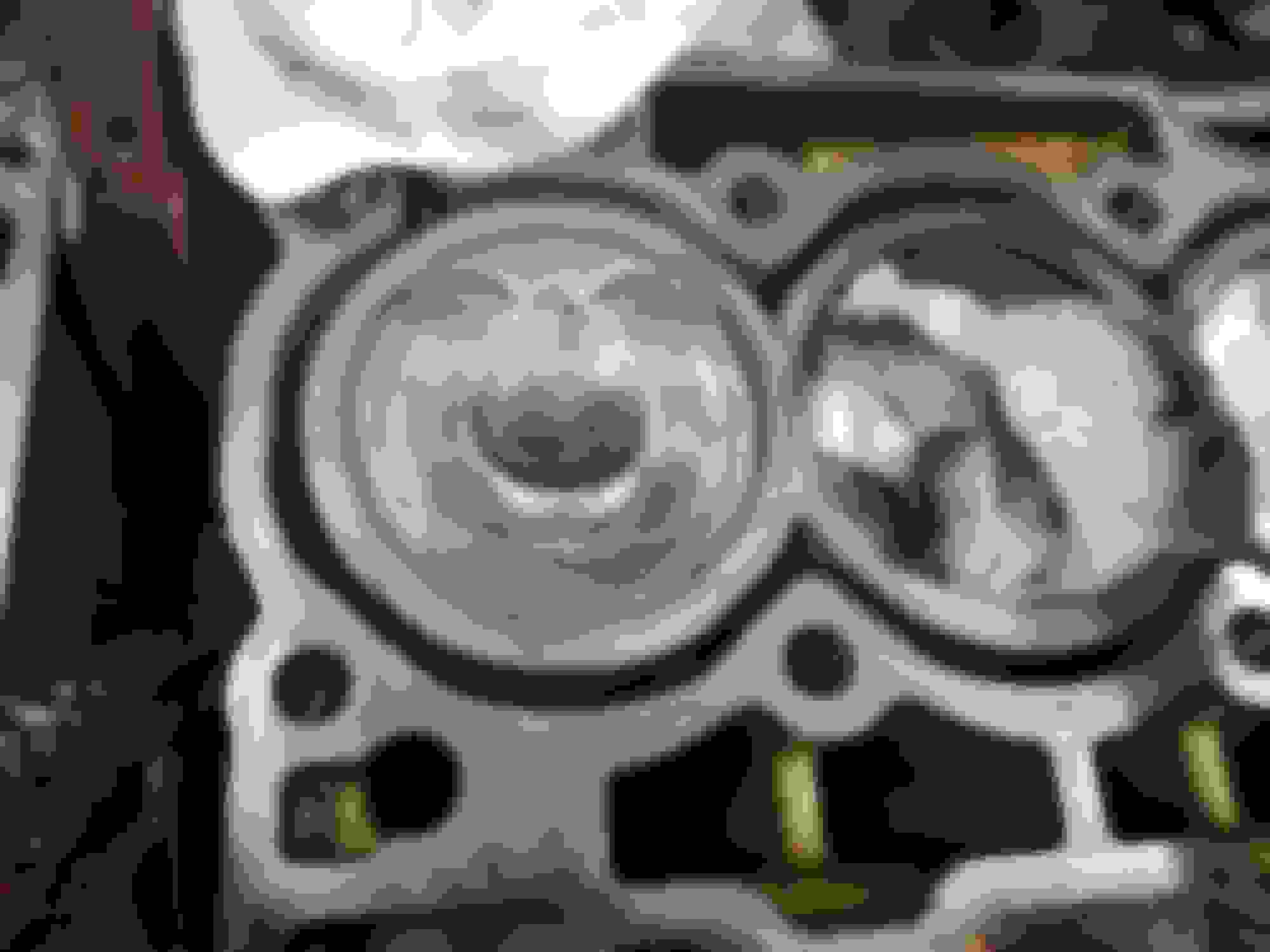
first attempt at setting timing. It all worked fine until I tried reinstalling the cam tools after baring it over. I got a little gap on the intake side. It does tighten down ok but It�s not oerfect.
I couldnt figure out the pretensioner at 5 in lbs so I just set it in a little. Does it mean to torque the center bolt down to 5 in lbs? This could be my problem. I will have to borrow a torque wrench that goes that low.
Chances are, the timing is close enough for a CR test. However, a little practice at getting it right isn't a bad idea.
How to use the pre-tensioner tool: Before installing into the block, back off the center bolt, so it will NOT engage the guide. Then install the tool finger tight. Then tighten the center bolt to 0.6Nm (or the in-lb equivalent). This should be done with at least the two cam sprockets loose and all guides in place. Ideally, the chain will have been run around a complete rev or two, CW, to ensure no kinks, etc --- this is the reason for repeating the timing tool install. My guess is, you have a small tool gap because there was a bit of slack in the chain on your first attempt.
The key to getting Mini Cooper timing correct is understanding how it works and what you're doing with the various components. Without the "traditional" keyways and locking devices found on most car timing mechanisms, Mini's timing setting can be hard to learn. Their system will function correctly, it's just not as adjustable, or capable of being modified for high performance as "traditional" systems.
Most digital torque wrenches don't like that small a setting. Try to find a "twin bar" type --- I've seen a couple on Amazon and they're a lot less expensive than a digital version. And, if you get into major repairs, there are other in-lb torque settings to be used --- you should consider owning your own torque wrench's --- �" & ⅜" drives.
Oldbrokenwind you are the best! Thanks.
I contacted my son, a mechanic at a dealership, and he is brining home the bar torque wrench with the compression tools tonight.
I have a variety of torque wrenches and tools, but apparently, the mini is used some 'different' stuff that I have. I have done lots of engine work over the years, but most were VWs and Chevys.
One last question...at least for now. The top center guide torque is 15 ft pounds for the two top bolts. That seems a lot for those bolts. One bolt just seems weird when I torque it down. I do them wrench tight and then with the torque wrench the inner bolt tightens and the outer turns more. I did not keep going so that I don't strip it. Is the Bently correct at 15 ft lbs?
Bentley has a couple errors --- this is one of them. Our top guide has two different bolt sizes, Bentley only shows the bigger one. There's a step in https://www.newtis.info/tisv2/a/en/ that shows this bolt as an M6 and tightened to 8Nm. It can be found under Repair Manuals and Technical Data - 11 Engine - 11 31 Camshaft - Repair Instructions (REP) Replacing the timing chain \PREMIUM
Bentley's "typo" has caused lotsa grief to several NAM members. Hopefully, you only have a stripped bolt --- easily replaceable. If head threads are stripped, your machine shop will have another task (if you also have a bent valve). It should be a simple task, just messy and best done with the head on a bench. What's it called, a nut-sert?
FYI --- another "typo" is the crankshaft center bolt torque spec. Couple years ago, Mini changed the bolt from 70mm long to 74mm, and the torque spec from 50Nm + 90 deg to 50Nm + 180 deg. This was done after Bentley published the manual. Maybe their version 2 has it corrected? Anyhow, this is the reason I strongly advised you to not loosen this bolt --- it's awkward to access and takes a very long wrench to get the added 180 deg.
good news is the timing was spot on after retorquing the pretentioner correctly.
Bad news is both #4 exhaust valves are stuck down.
The head has to come off. Didn�t do the compression check once we saw that.
Sorry to hear about #4. Shouldn't be a surprise tho, considering the condition when you got it.
So, now your "feet are wet" --- tore apart your first Mini and learned probably more than you wanted to. More to come! Be sure to tag all the electrical connectors as they're disconnected, and be careful to "unlock" each one. Hopefully your son, the mechanic, has experience doing this --- some of our connectors are pretty tricky, and many look alike.
Keep us posted on what else you find, if anything.
I see two options ---
1- leave them alone, do a good job on the head, reassemble
2- pull the pistons, wire brush or chemically clean the tops, reassemble
Too bad you didn't follow thru with the compression test. Cyl with bad valves will obviously fail, but now the other three are unknowns. Do you need rings? Whatever your choice, a CR should still be done.
Option 1 can be done without a complete reassembly, just enough to do a compression test using the rebuilt head. If CR is OK, a couple good runs (sometimes referred to as an Italian Tune-up) will clean a lot of the piston crud. If CR shows weak / bad rings, then pull pistons for clean-up and new rings. However, just replacing rings without re-boring may lead to oil consumption --- new rings in an out-of-round cylinder will not seat properly.
Option 2 is questionable for an old engine --- rings are worn and bearings get "disturbed". It's also a lot more work.
Your decision should depend on your ultimate use of this car and budget. A third option is a complete rebuild.
I have two spring compressors and neither will work to remove valves. One has a 3 inch extension to rest on the top of the piston. Any links to what is a good spring compressor to use?
Haven't tried it but it looks like Schley Products, Inc. part number 91400B will work. Available at Walmart for $125 several months ago. E-Bay too for $120 and free shipping.
If you replace the valves yourself, be sure to check and adjust the valve height. New valves can be too long and cause piston damage.
If you have no ridge, from piston ring wear at the cylinder wall top, then you most likely are good to go. Bring the pistons to the top and clean them right in the block. Protect the other cylinders while doing this. Use a 2 or 3 inch scotch pad disc and a little brake or carb cleaner. I use the pad on a right angle domore. Before you send the piston down the bore, to do the other two, spray some white lithium grease on to the piston trying to get down the side to the top ring. It'll hold any junk there to be wiped out once the piston is down. Just lap all the valves with lapping compound with a new set of seals it will be like new.
Valve Clearance:=leftIntakemm4.9605 ... 4.9755Exhaustmm4.9525 ... 4.9675
I can't find procedures on how to adjust the valve clearance. I've searched Bentley, TIS and YouTube. I read on NAM that they will not come in the proper length, so I must adjust them.
Also, I watched a video where they cleaned the injector nozzle with brake clean and a tooth brush. Is that a good idea? Never use anything but brake clean and a rag on nozzles before.
Where did you read they dont come in proper length? That would be like buying a water pump with the mounting holes elsewhere and it needs to be machined to fit. That doesnt make sense to me. Just buy stock replacements off rockauto. They should have the length listed. Use a good old one to measure length and buy that one. There is no valve clearance to adjust if your replacing valve for valve. Don't over think this
You're measuring overall length. My comment was referring to the installed stem height, probably measured before springs and seals are installed. It allows for variations in seat depth, excess grinding, etc. Here's a copy of a page out of a reference manual. There's a high probability that an OEM replacement will work just fine, altho I wouldn't take that chance. A simple measurement is great insurance.
OK, I can't get the file to upload. The measurements for both in and ex valves are 1.595" to 1.615" Document published by AERA --- Engine Builders Association.
Do you mean from the top of the valve to the bottom of the cam (when both are installed)?
Do you mean from the top of the valve to the bottom of the cam (when both are installed)?
As I understand it, the measurement is from the top of the stem to the hole-in-the-head where the stem protrudes. It's supposed to be how much stem is sticking out of the head. No cam installed, no spring, no seal, nothing but the head and valve. With mechanical lifters, there's an adjustment for valve lash, to keep the cam-to-valve distance a known value --- allowing the cam grind to function as advertised and allow the valves to close when not on a lobe. With hydraulic lifters, we don't have that adjustment, we can only set the valve-to-cam distance --- via grinding the stem.
Edit: Let me clarify --- I have NOT performed this measurement! I don't have the valve puller or the knowledge of how this measurement is to be performed. There must be some consistent, machined surface under or within the spring area, from which to measure. My last valve replacement was done by a shop known to have Mini experience, so I let them do the replacement, seating and adjustment, if needed.
Last edited by oldbrokenwind; Dec 30, 2018 at 07:10 PM.
If you have no ridge, from piston ring wear at the cylinder wall top, then you most likely are good to go. Bring the pistons to the top and clean them right in the block. Protect the other cylinders while doing this. Use a 2 or 3 inch scotch pad disc and a little brake or carb cleaner. I use the pad on a right angle domore. Before you send the piston down the bore, to do the other two, spray some white lithium grease on to the piston trying to get down the side to the top ring. It'll hold any junk there to be wiped out once the piston is down. Just lap all the valves with lapping compound with a new set of seals it will be like new.
Is that the green pad you are using (fine) or the medium ?
I have everything apart and cleaned up. Good news and I only have 4 bad valves. #4 exhaust and #3 intake valves were bent. Got them all clenaed up and lapped. Cleaned up the pistons and ready to order parts.
Hopefully I will be putting it back together very soon.
Can�t wait.
looking good!!!! if you have a large fine flat file (say that three times really fast) run it across the head and block mating surfaces to debur them and check for flatness. run the file at a 45 degree angle both ways to clean up the surface and check for level.