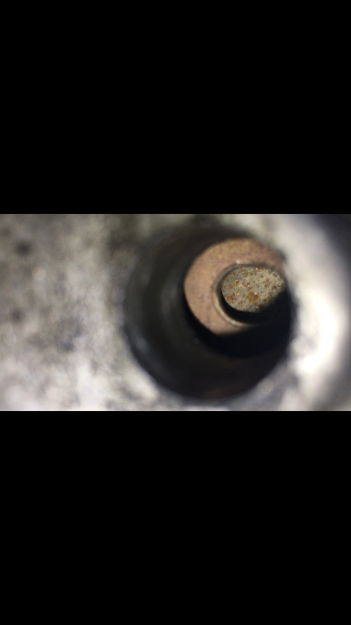
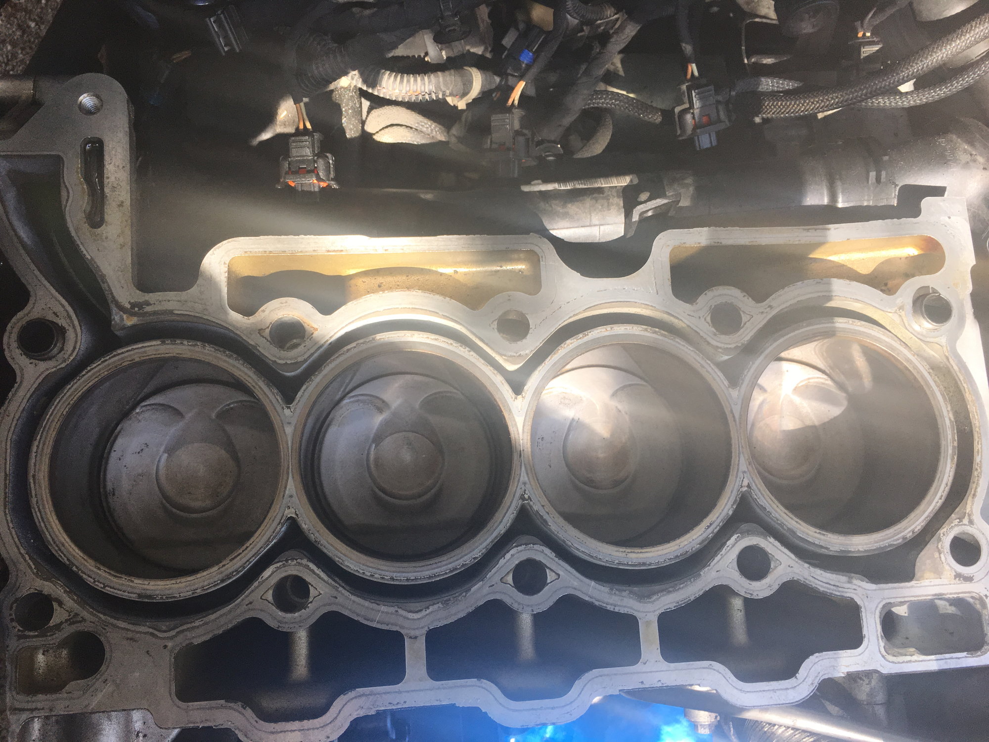
R56 08 Mini S cylinder head removal
#27
#28
When the locking pin is inserted thru the bell housing and into its mating hole in the flywheel, everything will be lined up correctly to follow the remaining instructions in your Bentley manual and the previous attachment. You'll have to rotate the crank, to find the mating hole. It's a tight fit and may be hard to find. Maybe start by using a small screwdriver to locate the flywheel hole, just hold the screwdriver perpendicular to the bell housing or you'll miss it. Here's a pic of what you're looking for. The other holes are for balancing and mounting. DO NOT substitute the screwdriver for the locking pin. It ain't locked until the pin is installed properly and doesn't fall out. There can be no flywheel movement!
#29
When the locking pin is inserted thru the bell housing and into its mating hole in the flywheel, everything will be lined up correctly to follow the remaining instructions in your Bentley manual and the previous attachment. You'll have to rotate the crank, to find the mating hole. It's a tight fit and may be hard to find. Maybe start by using a small screwdriver to locate the flywheel hole, just hold the screwdriver perpendicular to the bell housing or you'll miss it. Here's a pic of what you're looking for. The other holes are for balancing and mounting. DO NOT substitute the screwdriver for the locking pin. It ain't locked until the pin is installed properly and doesn't fall out. There can be no flywheel movement!
#31
Nvm what I said haha I'm just being way careful that sometimes I think everything is wrong. Anyways so far I have it to this point, and now I'm sanding down the locking pin because it doesn't fit in completely.
I posted photos to show the alignment..all good? Haha
Last edited by [My_Mini]; 09-23-2017 at 02:04 PM.
#33
Ok, is there any possible way where the pistons aren't able to align?
Nvm what I said haha I'm just being way careful that sometimes I think everything is wrong. Anyways so far I have it to this point, and now I'm sanding down the locking pin because it doesn't fit in completely.
I posted photos to show the alignment..all good? Haha
Nvm what I said haha I'm just being way careful that sometimes I think everything is wrong. Anyways so far I have it to this point, and now I'm sanding down the locking pin because it doesn't fit in completely.
I posted photos to show the alignment..all good? Haha
#34
So I put the head on, and placed the torques on, haven't completely tightened them in yet. Making sure, what are the total pounds to torque these in?
#35
This is where you gotta follow the Bentley manual --- tightening torque and sequence, for both the head and sprocket bolts. For me to try communicating this set of instructions is a responsibility I don't want. Screw it up with a typo, or not be specific about something, and you're S.O.L. TTY or stretch bolts have a very specific sequence to be followed, and it's all spelled out by Bentley. I've held your hand long enough. Maybe there's someone else out there willing to pick up where I'm leaving off, but so far it's been just you and me. Anybody else want the responsibility?
#36
This is where you gotta follow the Bentley manual --- tightening torque and sequence, for both the head and sprocket bolts. For me to try communicating this set of instructions is a responsibility I don't want. Screw it up with a typo, or not be specific about something, and you're S.O.L. TTY or stretch bolts have a very specific sequence to be followed, and it's all spelled out by Bentley. I've held your hand long enough. Maybe there's someone else out there willing to pick up where I'm leaving off, but so far it's been just you and me. Anybody else want the responsibility?
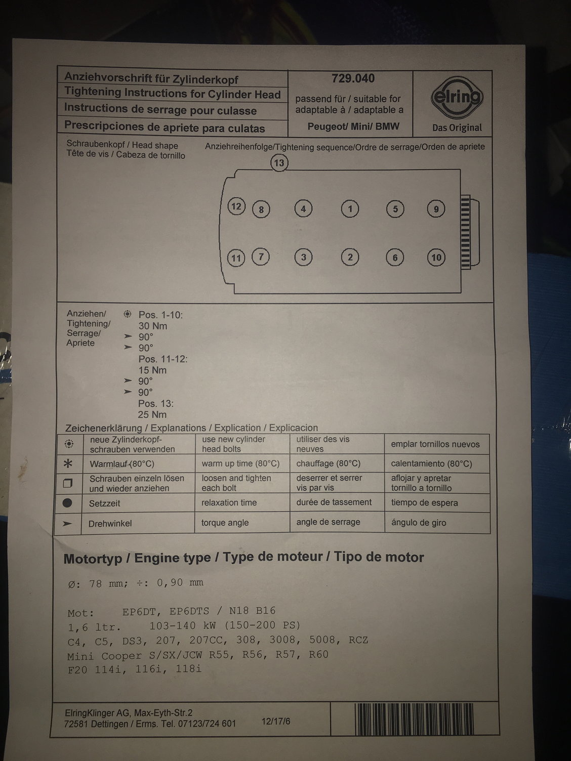
I think I will follow this since I've read some forums and there aren't specific specs about this. They also mention that the Bentley manual does not show the specs, I don't know, but I'll keep searching. This is the last step and I can finally put everything back together and try it out.
(Also I wish more people can put their input)
Last edited by [My_Mini]; 09-23-2017 at 09:24 PM.
#37
No Bentley manual! OK, here's some more info ---
How to read the head gasket bolt info ---
Pos 1 - 10:
Step 1. Tighten to 30Nm in sequence shown.
Step 2. Then tighten another 90 degrees in the same sequence.
Step 3. Finally tighten another 90 deg in the same sequence.
Pos 11 - 12:
Step 1. Tighten to 15Nm in sequence shown.
Step 2. Then tighten another 90 degrees in the same sequence.
Step 3. Finally tighten another 90 deg in the same sequence.
Pos 13:
Step 1. Tighten to 25Nm
Tighten the head before installing cams and sprockets.
Cam caps are 10 Nm
Note that each cam cap should be tightened a little bit at once, so that you don't have one cap tight while others are loose. The object is to minimize bending the shaft --- note that the valves are putting serious force on the cam in random positions while you tighten the caps. Don't worry about rotating or locking the cams until you have both installed and tightened.
Both sprocket bolts are 20Nm + 90 deg. NOT to be tightened until the chain is tensioned to spec --- see the attachment sent earlier.
#38
No Bentley manual! OK, here's some more info ---
How to read the head gasket bolt info ---
Pos 1 - 10:
Step 1. Tighten to 30Nm in sequence shown.
Step 2. Then tighten another 90 degrees in the same sequence.
Step 3. Finally tighten another 90 deg in the same sequence.
Pos 11 - 12:
Step 1. Tighten to 15Nm in sequence shown.
Step 2. Then tighten another 90 degrees in the same sequence.
Step 3. Finally tighten another 90 deg in the same sequence.
Pos 13:
Step 1. Tighten to 25Nm
Tighten the head before installing cams and sprockets.
Cam caps are 10 Nm
Note that each cam cap should be tightened a little bit at once, so that you don't have one cap tight while others are loose. The object is to minimize bending the shaft --- note that the valves are putting serious force on the cam in random positions while you tighten the caps. Don't worry about rotating or locking the cams until you have both installed and tightened.
Both sprocket bolts are 20Nm + 90 deg. NOT to be tightened until the chain is tensioned to spec --- see the attachment sent earlier.
How to read the head gasket bolt info ---
Pos 1 - 10:
Step 1. Tighten to 30Nm in sequence shown.
Step 2. Then tighten another 90 degrees in the same sequence.
Step 3. Finally tighten another 90 deg in the same sequence.
Pos 11 - 12:
Step 1. Tighten to 15Nm in sequence shown.
Step 2. Then tighten another 90 degrees in the same sequence.
Step 3. Finally tighten another 90 deg in the same sequence.
Pos 13:
Step 1. Tighten to 25Nm
Tighten the head before installing cams and sprockets.
Cam caps are 10 Nm
Note that each cam cap should be tightened a little bit at once, so that you don't have one cap tight while others are loose. The object is to minimize bending the shaft --- note that the valves are putting serious force on the cam in random positions while you tighten the caps. Don't worry about rotating or locking the cams until you have both installed and tightened.
Both sprocket bolts are 20Nm + 90 deg. NOT to be tightened until the chain is tensioned to spec --- see the attachment sent earlier.
#39
OK, here's what should be done next. Refer to the attached pics from Bentley. They show cam markings and lobe orientation for final installation.
After both cams are installed and caps are tight, LOOSELY install the cam sprockets and chain. This is a good time to install the top chain guide. Then rotate the cams as shown and install the cam locks. Crank is still locked! When cam locks are installed, install the chain tensioner tool. Ensure the center bolt is backed out far enough to allow the tool to fully seat in the block. Then tighten the center bolt to 0.6Nm (5.3 in-lbs). This is the tension required on the chain for correct timing. Then and only then, tighten the cam sprockets as directed. So far, everything is still locked and engine timing should be correct. Now, without loosening the tensioner tool center bolt, un-screw the tensioner and measure how far out the center bolt was turned to achieve the correct tension --- measurement is shown on the previous attachment from a few days ago. With only 20 - 30K miles, yours should be OK. Now it's time to install the actual tensioner --- 65Nm (48 ft-lbs). Any deviation from this procedure, and you're on your own!
Now it should be safe to remove all the locks. Highly recommended to crank the engine by hand a couple times, to ensure chain was installed on the sprockets correctly, and nothing slips. Then lock the crank, and verify the cam locks can be installed easily --- ensuring the cams follow the crank correctly.
Finally, remove the locks again and put everything else back together.
Hopefully you get this before going off on your own. Sorry if my schedule doesn't synchronize with yours. Cam sprocket bolts are single use only (stretch bolts) and once tightened, they cannot safely be reused.
#40
#41
I followed every step of the way, however something unusual happened, when I rotated the timing clockwise, did a few revolutions, I wanted to make sure all of the locks fit once again, had the camshaft with the lettering facing up, and the locks went in nicely, but when the time came to place the pin, the hole was no where to be found as the pin did not want to go in, and I checked with my camera to reassure myself. I have no clue about what went wrong, I don't even know what to do at this point. I placed in the pin to lock the pistons, and which meant that the camshaft lettering is facing down. Is that right?
Last edited by [My_Mini]; 09-27-2017 at 02:15 AM.
#43
#44
I followed every step of the way, however something unusual happened, when I rotated the timing clockwise, did a few revolutions, I wanted to make sure all of the locks fit once again, had the camshaft with the lettering facing up, and the locks went in nicely, but when the time came to place the pin, the hole was no where to be found as the pin did not want to go in, and I checked with my camera to reassure myself. I have no clue about what went wrong, I don't even know what to do at this point. I placed in the pin to lock the pistons, and which meant that the camshaft lettering is facing down. Is that right?
Another basic fact about various ways to find the crank's locking pin hole --- all cylinders will be at the same height 4 different times during one complete camshaft cycle. This method should be used ONLY for getting close to the proper pin hole location, and should be used in conjunction with camshaft lettering.
Now, in your specific case, with lettering facing down, unlock everything and try rotating the crank one more complete revolution. Then lock the crank BEFORE checking cams again. They should be OK if it was OK with lettering facing down --- check it to be sure. Crank should always be locked BEFORE checking cams. If NOT OK, then get two more cam sprocket bolts and start the timing chain adjustment process all over again --- using tensioner tool also!
A couple posts ago you wrote "What if the bolts on the sprocket aren't removed and are installed as is? And then the chain is placed?". If this was done and other "shortcuts" were also performed, I have no idea what your situation is, and I highly recommend you start the timing adjustment all over again, with new cam sprocket bolts.
As I mentioned at the beginning of this thread --- don't even think about doing this without a Bentley manual, especially with your lack of experience.
#45
A lesson from "Internal Combustion Engine Basics: 4-Cylinder, In-Line" --- when the camshaft(s) make one complete revolution, the crankshaft makes two. This means you can get the condition described above, if not done correctly.
Another basic fact about various ways to find the crank's locking pin hole --- all cylinders will be at the same height 4 different times during one complete camshaft cycle. This method should be used ONLY for getting close to the proper pin hole location, and should be used in conjunction with camshaft lettering.
Now, in your specific case, with lettering facing down, unlock everything and try rotating the crank one more complete revolution. Then lock the crank BEFORE checking cams again. They should be OK if it was OK with lettering facing down --- check it to be sure. Crank should always be locked BEFORE checking cams. If NOT OK, then get two more cam sprocket bolts and start the timing chain adjustment process all over again --- using tensioner tool also!
A couple posts ago you wrote "What if the bolts on the sprocket aren't removed and are installed as is? And then the chain is placed?". If this was done and other "shortcuts" were also performed, I have no idea what your situation is, and I highly recommend you start the timing adjustment all over again, with new cam sprocket bolts.
As I mentioned at the beginning of this thread --- don't even think about doing this without a Bentley manual, especially with your lack of experience.
#46
The first paragraph you wrote seems about right, i must have locked it, after the rotations, when the flywheel hole was not shown yet, meaning the revolutions I did were not true.. also to mention, I was able to remove the bolt from the exhaust sprocket, but it was super tuff to remove the bolt from the intake, i was close to shaving the bolt head so I left it alone...but now I have another issue, my helper made a mistake in leaving the cam locks on, then started the rotation, while I was under the car. This basically messed up the work. Would I have to lock the flywheel and then remove the tensioner, camshaft bolts, chain, to once again manually adjust the camshafts? Would that cause the valves to open? ..thanks again for taking your time to help me, I truly appreciate it!!...
This whole chain timing process is based on setting both the crank and cams to the correct rotational position, THEN installing a chain to keep this relationship constant. Note that all three sprockets are NOT keyed, as most other cars are --- these sprockets can be in any orientation to the crank / cams, but MUST be tightened to spec. Once a sprocket is loosened, the whole process has to be repeated, but rotating any one of the three items can cause piston / valve interference. That's why the cams must be removed when positioning things --- to keep valves closed. Serious emphasis on crank locking and cam lettering during installation. Ensure your "helper" knows all this too.
A hint to remove the cam sprocket bolt --- use an open-end wrench where the cam lock fits, to apply opposite torque when removing the bolt. If the bolt head is "ruined" you might have to drill it out, or put the bolt head in a bench vice and wrench the cam off.
#47
With "messed up work", yes, you need to start over! If cams were locked and crank was turned, there's a possibility timing is screwed up enough to need the cam caps removed (to close all valves) before rotating anything else --- your call! Lock the crank with cam lettering up, loosen the cam sprockets but don't remove the chain, THEN install / lock the cams. Remove tensioner and install tensioner tool. Both cam sprockets gotta be loose so chain tension is applied on both sides of the crank sprocket, which has never been loosened, correct? All the info I've furnished is assuming the crank sprocket is already tightened to spec.
This whole chain timing process is based on setting both the crank and cams to the correct rotational position, THEN installing a chain to keep this relationship constant. Note that all three sprockets are NOT keyed, as most other cars are --- these sprockets can be in any orientation to the crank / cams, but MUST be tightened to spec. Once a sprocket is loosened, the whole process has to be repeated, but rotating any one of the three items can cause piston / valve interference. That's why the cams must be removed when positioning things --- to keep valves closed. Serious emphasis on crank locking and cam lettering during installation. Ensure your "helper" knows all this too.
A hint to remove the cam sprocket bolt --- use an open-end wrench where the cam lock fits, to apply opposite torque when removing the bolt. If the bolt head is "ruined" you might have to drill it out, or put the bolt head in a bench vice and wrench the cam off.
#48
With "messed up work", yes, you need to start over! If cams were locked and crank was turned, there's a possibility timing is screwed up enough to need the cam caps removed (to close all valves) before rotating anything else --- your call! Lock the crank with cam lettering up, loosen the cam sprockets but don't remove the chain, THEN install / lock the cams. Remove tensioner and install tensioner tool. Both cam sprockets gotta be loose so chain tension is applied on both sides of the crank sprocket, which has never been loosened, correct? All the info I've furnished is assuming the crank sprocket is already tightened to spec.
This whole chain timing process is based on setting both the crank and cams to the correct rotational position, THEN installing a chain to keep this relationship constant. Note that all three sprockets are NOT keyed, as most other cars are --- these sprockets can be in any orientation to the crank / cams, but MUST be tightened to spec. Once a sprocket is loosened, the whole process has to be repeated, but rotating any one of the three items can cause piston / valve interference. That's why the cams must be removed when positioning things --- to keep valves closed. Serious emphasis on crank locking and cam lettering during installation. Ensure your "helper" knows all this too.
A hint to remove the cam sprocket bolt --- use an open-end wrench where the cam lock fits, to apply opposite torque when removing the bolt. If the bolt head is "ruined" you might have to drill it out, or put the bolt head in a bench vice and wrench the cam off.
This whole chain timing process is based on setting both the crank and cams to the correct rotational position, THEN installing a chain to keep this relationship constant. Note that all three sprockets are NOT keyed, as most other cars are --- these sprockets can be in any orientation to the crank / cams, but MUST be tightened to spec. Once a sprocket is loosened, the whole process has to be repeated, but rotating any one of the three items can cause piston / valve interference. That's why the cams must be removed when positioning things --- to keep valves closed. Serious emphasis on crank locking and cam lettering during installation. Ensure your "helper" knows all this too.
A hint to remove the cam sprocket bolt --- use an open-end wrench where the cam lock fits, to apply opposite torque when removing the bolt. If the bolt head is "ruined" you might have to drill it out, or put the bolt head in a bench vice and wrench the cam off.
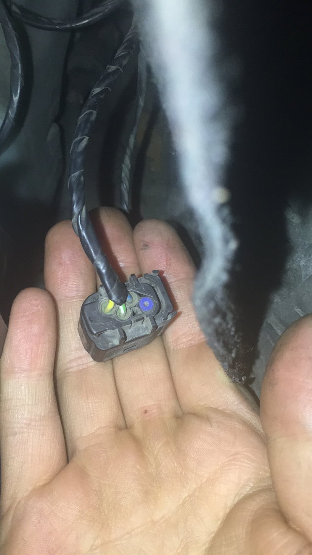
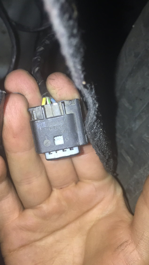
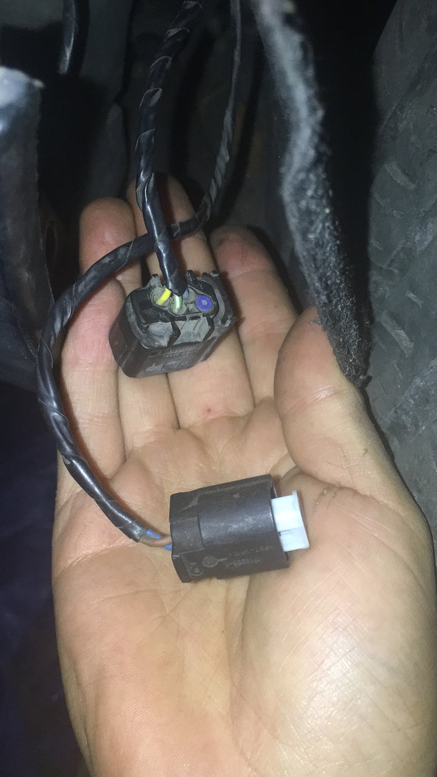
I know the wire below goes to the trim lights, but the bigger connector, I have no clue
Btw this is from the front left bumper
#49
#50
Wow! I had no clue! I don't even remember removing that connector but thank you so much!!! I finally finished my job with fixing this baby up and turning it on made me so anxious. But did it and the sound was music to my ears. Very happy with the results! Only thing that's worrying me is some smoke coming out from the turbo from under the heat shield, I'm assuming it's the oil line or it could be some of the left over burnt oil in that area, even though I did my best to clean it.


