R50/53 Bloody Mary - rusEfi DIY ECU testbed


Thread Starter
|
1st Gear
Joined: Aug 2012
Posts: 37
Likes: 0
From: Chicago
Bloody Mary - rusEfi DIY ECU testbed
I would like to introduce Bloody Mary - that's a red R50 which would the second testbed for my DIY ECU project.
Here she comes:

So yes, I am a bit crazy because I am developing an DIY ECU in spare time. I've got some progress on the first test vehicle which is an older, much simpler car - and now I am starting to look into the Mini. First step would be making an ECU harness so that I can put the ECU on the passenger seat and sniff what's going on in these wires.
The 121 pin ECU connector is pretty popular, I have the same connector on my Nissan truck, and the same connector is used by Korean cars which are already waiting for me at junk yards - so, Hyundai would help with raw materials:

This Hackaday article gives an idea of where all this is right now.
Here she comes:
So yes, I am a bit crazy because I am developing an DIY ECU in spare time. I've got some progress on the first test vehicle which is an older, much simpler car - and now I am starting to look into the Mini. First step would be making an ECU harness so that I can put the ECU on the passenger seat and sniff what's going on in these wires.
The 121 pin ECU connector is pretty popular, I have the same connector on my Nissan truck, and the same connector is used by Korean cars which are already waiting for me at junk yards - so, Hyundai would help with raw materials:
This Hackaday article gives an idea of where all this is right now.
Thread Starter
|
1st Gear
Joined: Aug 2012
Posts: 37
Likes: 0
From: Chicago
It was naive of me to assume that all 121 pins connectors are compatible :( They are not. On this picture both connectors are made by AMP, but they are different kinds :(
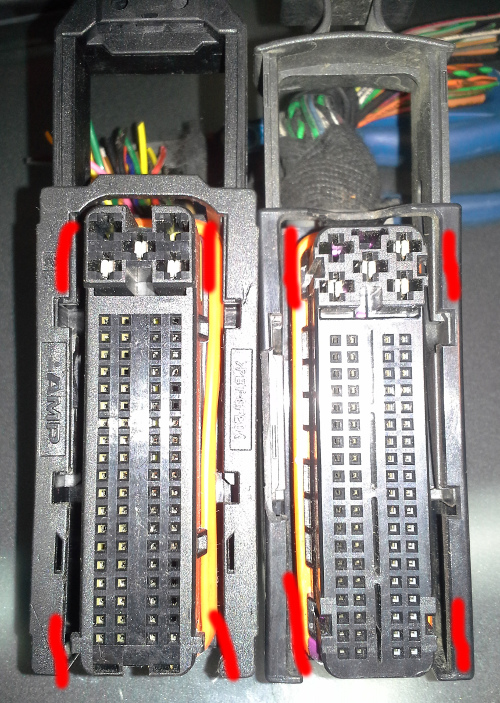
Mini connector is compatible with IV gen Jetta VR6 - plenty of these in junk yards now. Mini connector is not compatible with Hyundai.
Mini connector is compatible with IV gen Jetta VR6 - plenty of these in junk yards now. Mini connector is not compatible with Hyundai.


2nd Gear
Joined: Feb 2013
Posts: 58
Likes: 0
A very ambitious project indeed. I have a couple questions though.
1. Why do you need a connector that connects to the factory ECU if you are getting rid of that ECU with your own. Don't you need a connector that goes to the factory harness so that you can get the signal wires from the various sensors that you need to intercept in order to make your stand-alone system work?
2. Why no Megasquirt? If you want a non-vehicle specific raw application ECU's with tons of options, they've already got this covered.
I may not see the point of this and if I'm missing it, my apologies.
Thread Starter
|
1st Gear
Joined: Aug 2012
Posts: 37
Likes: 0
From: Chicago
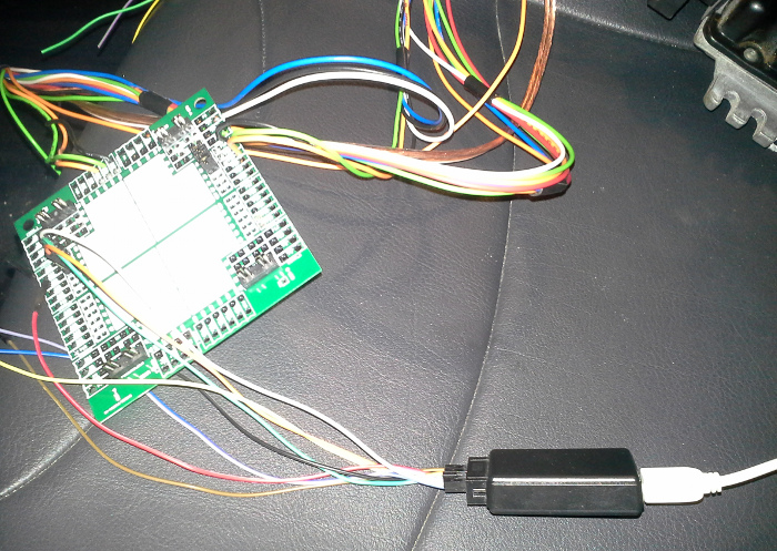
#1 - the connector: for the research phase I need to sniff what's going on while the engine is actually running. While technically I can cut the existing harness open, I'd rather take a less intrusive path - I am putting a T-shaped harness extension in between the stock harness and stock ECU. As a matter of fact, at some point I would have TWO ecus connected to the vehicle - with half of the wires going to the stock ECU and half of the wired going to my ECU. So, first phase is a plain harness to confirm which wires are less important. Next I cut the harness and build the T-junction. I hope it would start making more sense while I move forward. You can check this thread - http://rusefi.com/forum/viewtopic.php?f=4&t=454 - for the breakout board.
#2 https://www.kickstarter.com/projects...ject_faq_85742 :
Q: Isn't Megasquirt already offering open source customizable ECU's?
A: No, Megasquirt is offering a closed-source customizable ECU. I believe MS used to be 'open source but not free' (their license requires use of their authentic hardware). People were confusing 'open' for 'free' so MS had to switch to closed-source. rusEfi is a GPL open-source.
2nd Gear
Joined: Feb 2013
Posts: 58
Likes: 0
Andrey,
This makes more sense to me now. You are developing an ECU that you can have completely open access to mapping for all different applications available. Once the ECU is purchased, the maps are freely shared. Ambitious but you seem to have the right ideas.
Very cool!
Keep up the hard work.
This makes more sense to me now. You are developing an ECU that you can have completely open access to mapping for all different applications available. Once the ECU is purchased, the maps are freely shared. Ambitious but you seem to have the right ideas.
Very cool!
Keep up the hard work.
Trending Topics
Thread Starter
|
1st Gear
Joined: Aug 2012
Posts: 37
Likes: 0
From: Chicago

I am starting with the smaller 40p connector. I've wired
82/1 Acceleration Pedal
83/2 Acceleration Pedal
86/5 Acceleration Pedal
87/6 Acceleration Pedal Ground
105/24 Fuel Pump
107/26 Acceleration Pedal
108/27 Acceleration Pedal
114/33 ECU Ground
115/34 ECU Ground
118/37 Fuel Pump
120/39 +12V
121/40 Power +12V all times
but it would not start. So I am back to the wiring diagram, apparently it needs more wires to be in place. Clutch switch module maybe?
I've got the diagram on my http://rusefi.com/wiki/index.php?tit...ni_Cooper_2003 wiki
Thread Starter
|
1st Gear
Joined: Aug 2012
Posts: 37
Likes: 0
From: Chicago
I've missed two important wires.
Now, with addition of
85/4 Clutch switch
97/16 From main relay
106/25 Anti-theft system
The car starts & revs via my harness extension. Next step - same thing for the larger connector.


Thread Starter
|
1st Gear
Joined: Aug 2012
Posts: 37
Likes: 0
From: Chicago
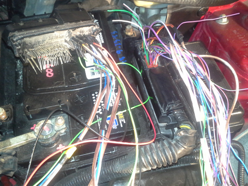
Got the minimalistic harness extension: no coolant temp, no CAN. While the car starts it is surely confused, but that's OK for my purposes.
Next step would be to cut some of the wires, make a T-junction and sniff what's going on in the wires.
PS: did I mention https://www.kickstarter.com/projects...-unit-ecu-firm?