
R50/53 R53 OEM bluetooth retrofit

Thread Starter
|
3rd Gear

Joined: Jul 2012
Posts: 157
Likes: 11
From: Chicago
Replacement kit arrived! Complete with ULF. So everything's included but URL TBD instructions are in German :-) I've updated the pics and posts above. The install is definitely involved.
EDIT: I annotated and translated the install doc, available URL TBD here
EDIT: I annotated and translated the install doc, available URL TBD here
Last edited by bradnic; Jan 20, 2018 at 07:43 PM.
Thread Starter
|
3rd Gear
Joined: Jul 2012
Posts: 157
Likes: 11
From: Chicago
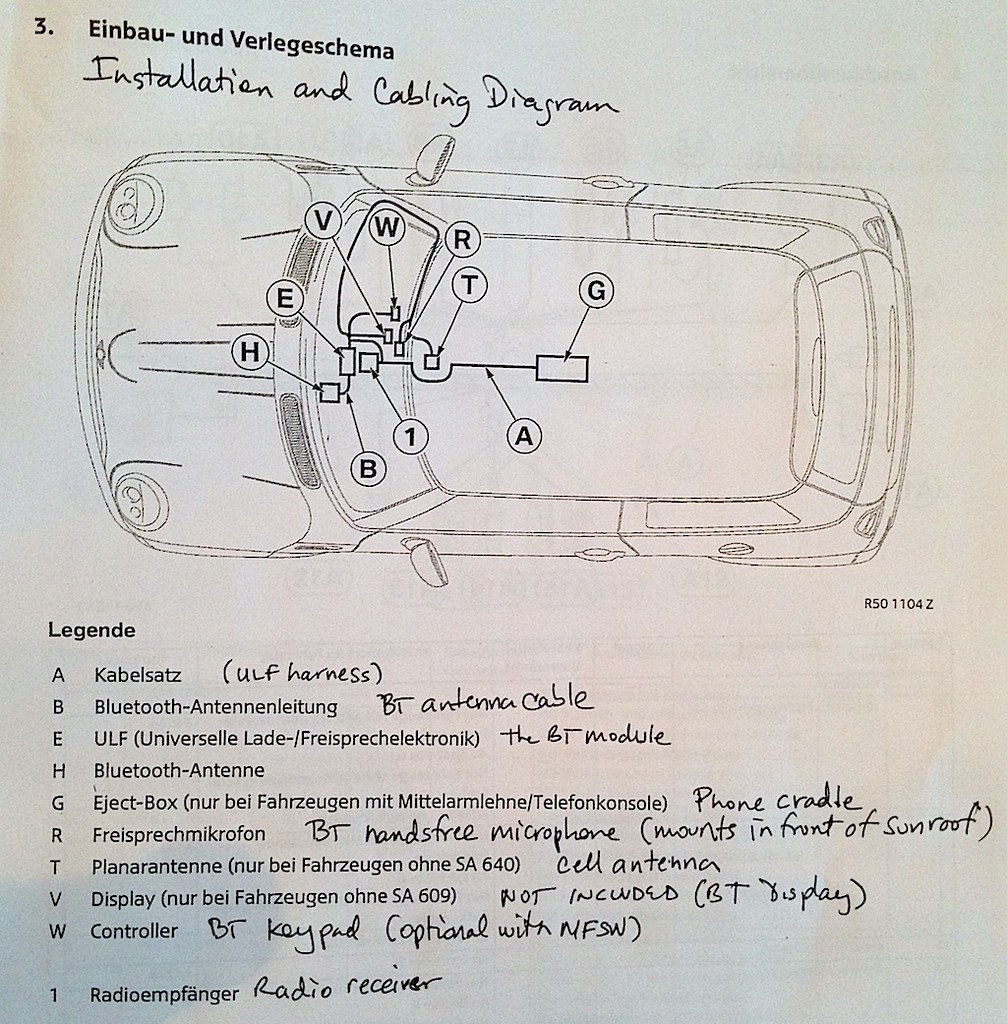
Installation overview and some general advice
I translated a couple of pages including general instructions and part inventory. still need to go through the wiring harness diagram and understand all the stuff there. I have been taking detailed notes/translation on the hard copy and will scan them when done.
I've also been PMing with Mike at ECS. He installed this exact kit in a non-nav R53 a few years back so he's very familiar with it. I must say I'm very glad I've purchased through them.
Some quick facts:
- instructions vary depending on what's installed in your car. Most of the option specific stuff is related to connecting the ULF harness to the radio. The following options are listed in the instructions as affecting installation:
SA 249 Multifunction steering wheel (makes a little BT keypad optional)
SA 403 Glass roof (affects microphone mounting and what trim to use. there also appears to be a different mounting requirement for the panorama roof compared to the regular sunroof. will know more once I pull the trim on my car)
SA 609 Navigation system Professional (minor differences)
SA 640 phone preparation (you need a different antenna adapter if you have this, which is included in the kit)
SA 656 Radio Wave (some radio specific wiring instructions)
SA 657 Radio Boost (some radio specific wiring instructions)
- this kit type ("nav" version, 84-64-0-404-810) is the last OEM universal handsfree retrofit kit available for R50/R52/R53. The other "non-nav" kit ("811" at end of part number) is definitely NLA. If you have any interest in this retrofit you should seriously consider picking one up soon.
- you don't really need to use a phone snap-in - you can keep the generic cradle cover and drop your phone on top of it. You will need to wire power to charge your phone though, and you may want to mod the cradle cover to fit the wire through.
- even though this is a "nav" kit, it works with non-nav cars. I'm still going through the instructions to understand the nav dependencies and any harness impacts.
UPDATE: KIT INSTALLED IN NON-NAV 06 R53 - WORKS PERFECTLY. EVERYTHING NEEDED WAS INCLUDED.
- the instructions talk about an additional "BT display" that gets mounted above the center speedo gauge in cars without SA 609 nav. this is not included in the kit. Mike from ECS told me this was something seen in europe models but not used in the US. I certainly would only want to use the radio display in my non-nav car. nav equipped cars of course have a wonderful screen for the phone function display, so they don't need this other display anyway.
NOTE: it makes you wonder why this BT display was listed in the instructions if this is a "nav kit".. possibly these instructions were for the "811" kit also.
- the kit includes a "stealth" GSM/UMTS car antenna for cars without SA 640 phone prep that's mounted hidden and helps cellphone reception when the phone is in the cradle. Not sure how well it works with CDMA (Verizon, Sprint) or the new LTE stuff.
UPDATE: most of the wiring to the radio is focused on a single large radio plug labeled X18126 in the instructions. quite a bit of work there and some differences depending on the type of radio (e.g., which pin to connect some specific wires to)
Some general advice for the installation
- keep your hands clean (!!) hard to do when you touch the harness. you will absolutely stain your trim if you're not careful, and it's really easy to do.
- if you need to remove trim with a tool, try to manipulate the part where there is no direct line of sight in case you accidently scratch it
- try to understand where the trim part is fastened, and apply pressure there when possible. this will help prevent twisting or breaking
- where possible put the fasteners back where you pulled them out. It will save you alot of aggravation later. Just remember to remove the fastener before putting the part back on!
- clean and detail everything before reassembly. mild dishwashing soap and a sponge work very well on interior parts
Here's the "installation and cabling diagram" so you can get a feel for what's involved
Last edited by bradnic; Jan 20, 2018 at 07:44 PM.
Thread Starter
|
3rd Gear
Joined: Jul 2012
Posts: 157
Likes: 11
From: Chicago
DOC LINKS TO BE UPDATED
Making good progress on the doc translation. It helps that I just went through a major nav retrofit on my E46 and had english BMW install docs!
Section 2, page 6 = Prep work for the bluetooth install
EDIT: I have added TIS service instructions (or user gen'd ones if they were better) where I could find them - just click on the part name
Disconnect negative battery terminal first
Remove all of the following components before beginning installation
- Rear center console
- Front center console
- Radio receiver
- Upper instrument cowl (!) yes that's the top instrument panel dash pad
NOTE: it's not listed in the install doc but to get the dash pad off you also need to pull the glovebox assembly (5 screws, easy) and the instrument panel trim (passenger, center, driver).
- Both A-pillar trim (R50/R53 after July 04, and the R52)
NOTE: if you have the a-pillar airbags like I do it's a very big deal to remove the a-pillar trim (also likely to be expensive). whatever you decide to do here is YOUR RESPONSIBILITY NOT MINE.
- L&R sun visors and "counter bearings" (I assume that means the visor mounts)
NOTE: only the right hand visor and mounts really need to be removed. the only reason for removal is to install some wires for the mic and antenna
- Interior mirror
- Visor handsfree microphone (R50/R53 cars with SA403 and R52)
- You need access to the front part of the headliner, which is why the mirror and visors are removed
- Center instrument cluster and instrument panel trim
- Nav Display (SA 609 cars only)
That is ALOT of disassembly work.
UPDATE: Installation complete. The most difficult part was the dashpad removal (top of the instrument panel). The only installation related reason you need to do this is to route a cellphone antenna and bluetooth microphone harness up to the rear view mirror area. Given there are airbags involved it would be easier to do the following:
- leave the dashpad, driver instrument panel trim and a-pillar in place
- find a way to route the harness to the right A-pillar without going through the top of the dash.
Of course if you absolutely want an "OEM install" by all means proceed. I did.
Last edited by bradnic; Jan 20, 2018 at 07:45 PM.
Thread Starter
|
3rd Gear
Joined: Jul 2012
Posts: 157
Likes: 11
From: Chicago
Harness diagram translated and labeled. you can see most of the wires are going to the radio connector. lots of work to do there.
UPDATE: most of the work is around the X18126 radio plug (mostly taps for the ULF module related to power and ground and iBus. There's also a couple of telephone on and mute signal wires). If you want an Aux-In cable also you will have to merge that with the ULF harness. I included step be step with pics for this later in the thread.
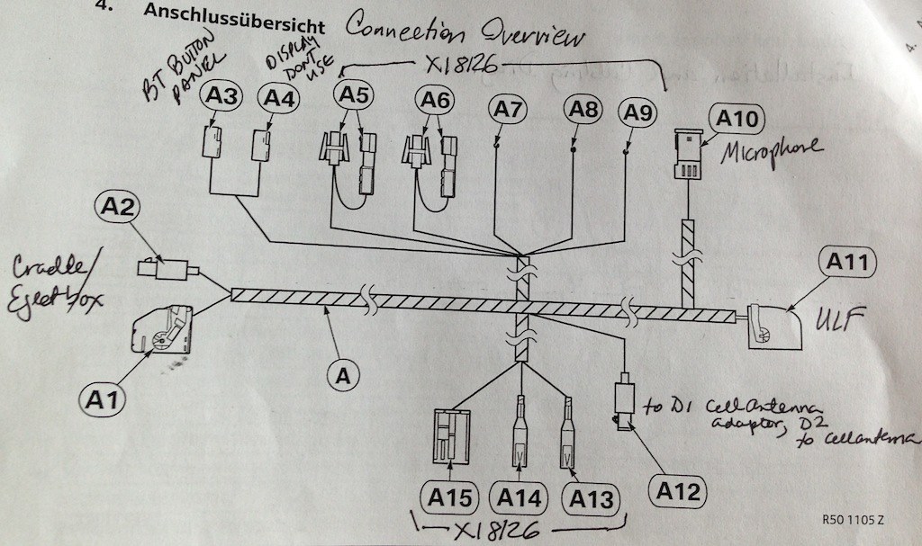
UPDATE: most of the work is around the X18126 radio plug (mostly taps for the ULF module related to power and ground and iBus. There's also a couple of telephone on and mute signal wires). If you want an Aux-In cable also you will have to merge that with the ULF harness. I included step be step with pics for this later in the thread.
Last edited by bradnic; Jan 20, 2018 at 07:46 PM.
Thread Starter
|
3rd Gear
Joined: Jul 2012
Posts: 157
Likes: 11
From: Chicago
Finally ready to start install; info about console armrest retrofit
Just finished annotating the install instructions in English. Finally going to start the retrofit! will post plenty of pics. As mentioned earlier:
1) an armrest console is mandatory. Overview info from Motoringfile here. If you don't have one ECS sells the OEM retrofit kit for it 51-1-60-398-467. I believe outmotoring.com does too. They have excellent armrest console install instructions here. They also had the OEM armrest console retrofit instructions. Of course don't install it until after step 4 below :-)
2) the front and rear console, radio, instrument panel trim, instrument panel top cover and a-pillars all have to be removed. Once that's done the rest of the install is not that bad
3) if you have any wiring mods from stock you will need to either reverse them or figure out if you need to adapt the ULF harness and how. You can use the schematic in the back of the install instructions for guidance. In my case I will be removing the factory iPod adapter as well as a Parrot system. The iPod adapter removal is actually not trivial because it requires you to put some pins and wires back into the radio connector. This can be a bit involved :-)
4) you tuck the ULF harness under the carpet, starting below the radio. one end of the harness comes up at the rear of the armrest console
UPDATE: It's much easier to install the harness in the console area if you pull the passenger seat out. you should probably pull the driver seat too as you will also need to modify an instrument panel mounting bracket just to the left of the radio opening near the steering column cover. DO NOT remove seats without the battery disconnected. You WILL set off the air bag warning light and trigger a dealer visit.
5) you have to crimp some wires on to the existing radio plug, and insert a connector there as well.
6) there's a cell phone antenna that gets mounted near the rear view mirror, and the bluetooth microphone is installed in the switch panel in front of that. The cellphone antenna cable and a harness gets routed up there as well via the right A-pillar
UPDATE: if you have a rain sensor in your car in front of the rear view mirror you can mount this antenna to the side of it. I tried sticking it to the sensor itself and eventually just tucked it into the headliner.
7) reassembly and test. no dealer coding is required which is good news.
This will get you OEM bluetooth phone support. There's more to do for A2DP, aux in etc. If you're using an intravee with a cradle it will need to be modded as well. Will document this stuff as I go along.
Last edited by bradnic; Apr 15, 2013 at 12:59 PM.
Thread Starter
|
3rd Gear
Joined: Jul 2012
Posts: 157
Likes: 11
From: Chicago
Harness laid out, all electronics interconnected
Everything in this pic comes with the kit, except the iPhone 4 snap-in (and phone of course).
Full harness, ULF, antennas and cradle
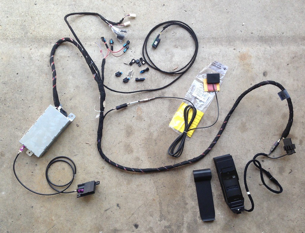
Cradle, snap-in and phone
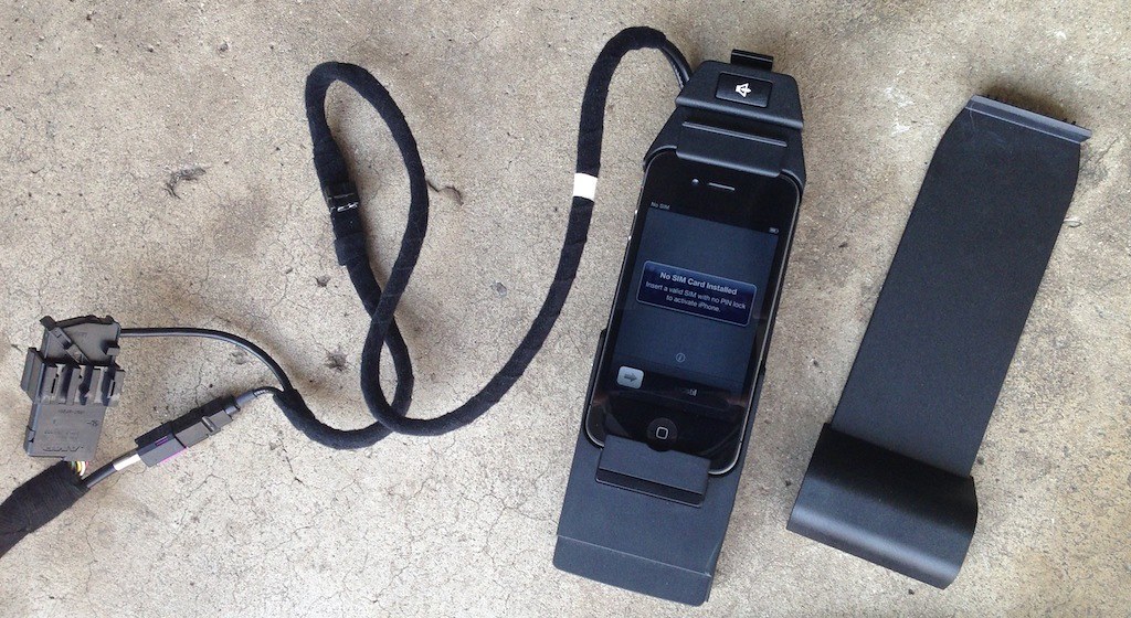
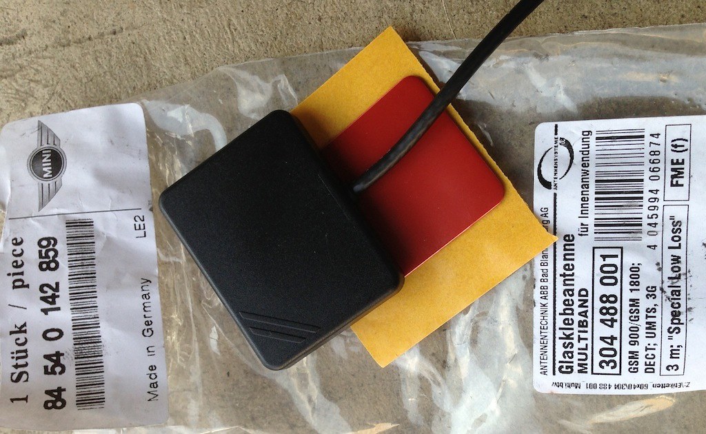
Bluetooth antenna
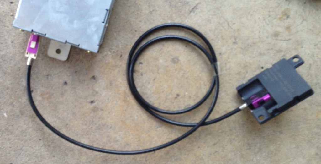
Cell antenna
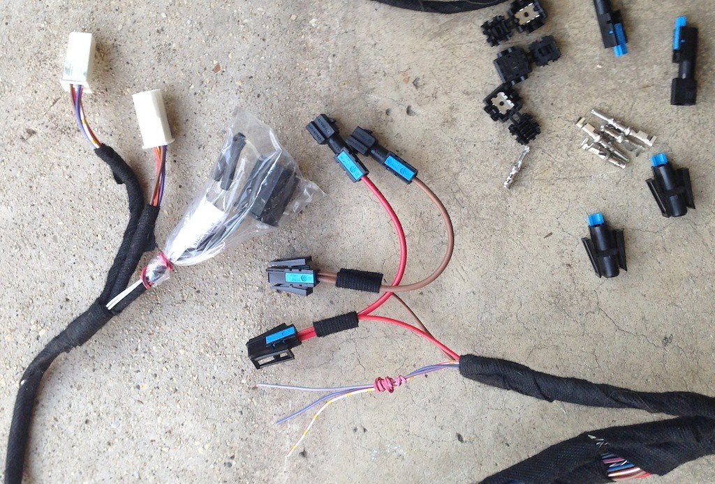
Radio interconnect wires, connectors and hardware
Note the iBus wire at the bottom - white, red stripe, yellow dots
Full harness, ULF, antennas and cradle
Cradle, snap-in and phone
Bluetooth antenna
Cell antenna
Radio interconnect wires, connectors and hardware
Note the iBus wire at the bottom - white, red stripe, yellow dots
Last edited by bradnic; Jan 20, 2018 at 07:51 PM.
Thread Starter
|
3rd Gear
Joined: Jul 2012
Posts: 157
Likes: 11
From: Chicago
getting started - rear console
this is a great opportunity to detail the interior.. lots of old starbucks accidents over the years..
start the job right

absolutely disconnect the battery

doc access is really handy especially for the installation guide and the TIS documents

don't pull on the rear brake boot or you'll break the leather loose! not hard to repair but best avoided

you need to squeeze the sides and lift gently


Probably not necessary but I pulled the boot completely off by cutting the cable tie. it's easily replaced and this way I won't risk damaging the boot when working the console and harness. make sure the hook on the cable tie faces down when you reassemble. the rear console TIS doc also talks about removing the chrome trim and ebrake handle leather sleeve. don't see the need to do that here


lift the rubber mats on the front side of rear console and remove screw


same for the rear cup holder (man that crud on there's gross)


pull screw on both rear console side trim pieces


lift the rear cup holder trim to remove


pull console forward and up to loosen. You will need to pull pretty firmly. DON'T pull completely out yet though as the tire monitor switch is still connected


GENTLY maneuver the console until you can get to the tire pressure switch connector. DON'T PULL IT. You need to put a pin in a hole to remove the connector safely.


take a look at the back side of the rear console and make sure you have all 4 plastic clips. one of mine stayed in the console mounting frame when I pulled it (bottom left one in the pic). make sure any missing clips get slid into place for reassembly


1st gen minis had alot of UK content - cool to see


this is the rear console base. it will need to be removed too to slide the harness under it. the rear console armrest will also come so we can route the cradle harness (and other stuff) through it

start the job right
absolutely disconnect the battery
doc access is really handy especially for the installation guide and the TIS documents
don't pull on the rear brake boot or you'll break the leather loose! not hard to repair but best avoided
you need to squeeze the sides and lift gently
Probably not necessary but I pulled the boot completely off by cutting the cable tie. it's easily replaced and this way I won't risk damaging the boot when working the console and harness. make sure the hook on the cable tie faces down when you reassemble. the rear console TIS doc also talks about removing the chrome trim and ebrake handle leather sleeve. don't see the need to do that here
lift the rubber mats on the front side of rear console and remove screw
same for the rear cup holder (man that crud on there's gross)
pull screw on both rear console side trim pieces
lift the rear cup holder trim to remove
pull console forward and up to loosen. You will need to pull pretty firmly. DON'T pull completely out yet though as the tire monitor switch is still connected
GENTLY maneuver the console until you can get to the tire pressure switch connector. DON'T PULL IT. You need to put a pin in a hole to remove the connector safely.
take a look at the back side of the rear console and make sure you have all 4 plastic clips. one of mine stayed in the console mounting frame when I pulled it (bottom left one in the pic). make sure any missing clips get slid into place for reassembly
1st gen minis had alot of UK content - cool to see
this is the rear console base. it will need to be removed too to slide the harness under it. the rear console armrest will also come so we can route the cradle harness (and other stuff) through it
Last edited by bradnic; Apr 23, 2013 at 12:13 PM.
Thread Starter
|
3rd Gear
Joined: Jul 2012
Posts: 157
Likes: 11
From: Chicago
armrest removal and cradle installation
you can see the side trim screw on the rear armrest mount. I like to put screws back when I can so they don't get mixed up or lost. 5 30mm torx screws need to be removed, then the armrest slides right out.

armrest removed

if you've never tilted the top lid before surprise! it tilts :-) You'll need to do that to remove it. DON'T FORCE THINGS. slide it all the way back. it should click in to place, then you can push on the back of the armrest cover and it will tilt. If it doesn't just jiggle it a bit until it's slid into position.

once it's tilted you will need to reach in and squeeze the clips a bit to take the cover out.


pull up the rubber mat - note the small torx screw at the rear

remove the rear cover screw

lift up and rotate the cover to remove it. don't force it as it has a slot on the bottom. you can see the wire channels for the harness, and that there is an opening in the back now. we will use one side for the cradle. if you want to install a phone charging/USB cable, aux input wire etc the other side is available for that.

NOTE: be sure you leave slack in the harness so that the armrest tilts properly.
snap-in installed - without the generic cover

with the generic cover in place

with the iphone4 snap-in. note there's plenty of room on the sides, unlike my E46 M3. so it looks like there's no need to sand the edges of the snap-in down - it should fit with no issues!

with the armrest cover installed - now you can see why the cover tilts. can't reach the home button on the iPhone without tilting the cover


done for now (will do aux and power for a2dp adapter as well as iphone 30pin cable later. also thinking about fitting a lightning to 30 pin adapter). you can also mod the generic cover to support other phones if you want

on to the front console
armrest removed
if you've never tilted the top lid before surprise! it tilts :-) You'll need to do that to remove it. DON'T FORCE THINGS. slide it all the way back. it should click in to place, then you can push on the back of the armrest cover and it will tilt. If it doesn't just jiggle it a bit until it's slid into position.
once it's tilted you will need to reach in and squeeze the clips a bit to take the cover out.
pull up the rubber mat - note the small torx screw at the rear
remove the rear cover screw
lift up and rotate the cover to remove it. don't force it as it has a slot on the bottom. you can see the wire channels for the harness, and that there is an opening in the back now. we will use one side for the cradle. if you want to install a phone charging/USB cable, aux input wire etc the other side is available for that.
NOTE: be sure you leave slack in the harness so that the armrest tilts properly.
snap-in installed - without the generic cover
with the generic cover in place
with the iphone4 snap-in. note there's plenty of room on the sides, unlike my E46 M3. so it looks like there's no need to sand the edges of the snap-in down - it should fit with no issues!
with the armrest cover installed - now you can see why the cover tilts. can't reach the home button on the iPhone without tilting the cover
done for now (will do aux and power for a2dp adapter as well as iphone 30pin cable later. also thinking about fitting a lightning to 30 pin adapter). you can also mod the generic cover to support other phones if you want
on to the front console
Thread Starter
|
3rd Gear
Joined: Jul 2012
Posts: 157
Likes: 11
From: Chicago
front console
since the harness runs underneath the front console it must be removed too. I'm leaving the front and rear console bases in for now until I'm ready to route the harness.
remove the shift **** by pulling straight up

pull up firmly on the shift boot ring to separate it

cut the cable tie on the shift boot (very easy to replace)

front cupholders have screws on them

UPDATE: The mirror switch was the only thing I damaged in this project. BE CAREFUL. Do not torque or pull on the buttons. The 6 clips underneath are pressed into the switch housing plastic, which breaks VERY easily.
removing the power mirror switch panel is hard because there are SIX pretty strong clips underneath. you need to be patient to avoid scratching the finish or potentially damaging the switches and switch buttons. in my case one of the retaining clips fell out and slid under the carpeting. will take a while to fish it out. I also had one of my heated seat buttons come apart. so consider yourself warned :-)

looking from the console boot area back you can see 2 clips. there are of course 2 matching clips on the rear side, plus another 2 on the left and right ends of the switch panel

grab some tools and some patience, push the clips in on the front side and then wiggle the switch panel until it clears the clips. then rotate the rear side of the switch panel from underneath to break it loose.

there are a pair of connectors underneath for each option you have (mirrors, heated seats). everything's keyed so you can't really get the connectors back in the wrong place. make sure you're careful removing the clips.
NOTE in the pic that one of the retainer clips is missing. It popped off during removal and slid under the carpet. BE CAREFUL with that previous step. It's definitely the hardest thing so far.

after that remove the 2 screws underneath.

finally, disconnect the front lighter from underneath


you can move on to the center stack supports that surround the radio, climate control and switch panel.
remove the shift **** by pulling straight up
pull up firmly on the shift boot ring to separate it
cut the cable tie on the shift boot (very easy to replace)
front cupholders have screws on them
UPDATE: The mirror switch was the only thing I damaged in this project. BE CAREFUL. Do not torque or pull on the buttons. The 6 clips underneath are pressed into the switch housing plastic, which breaks VERY easily.
removing the power mirror switch panel is hard because there are SIX pretty strong clips underneath. you need to be patient to avoid scratching the finish or potentially damaging the switches and switch buttons. in my case one of the retaining clips fell out and slid under the carpeting. will take a while to fish it out. I also had one of my heated seat buttons come apart. so consider yourself warned :-)
looking from the console boot area back you can see 2 clips. there are of course 2 matching clips on the rear side, plus another 2 on the left and right ends of the switch panel
grab some tools and some patience, push the clips in on the front side and then wiggle the switch panel until it clears the clips. then rotate the rear side of the switch panel from underneath to break it loose.
there are a pair of connectors underneath for each option you have (mirrors, heated seats). everything's keyed so you can't really get the connectors back in the wrong place. make sure you're careful removing the clips.
NOTE in the pic that one of the retainer clips is missing. It popped off during removal and slid under the carpet. BE CAREFUL with that previous step. It's definitely the hardest thing so far.
after that remove the 2 screws underneath.
finally, disconnect the front lighter from underneath
you can move on to the center stack supports that surround the radio, climate control and switch panel.
Last edited by bradnic; Apr 15, 2013 at 01:03 PM.
Thread Starter
|
3rd Gear
Joined: Jul 2012
Posts: 157
Likes: 11
From: Chicago
center stack
once the front console is ready to come out you still need to remove the 2 center stack pillars at the same time. then everything will come out at once. just remove the 2 screws on either side of the pillars.
to get access to the pillar screws you will need to remove the steering column cover


open the glovebox to get to the top screw on the right side


once the pillars are loose pull them forward at the top to clear the dash. then you can rotate the front console up and out with the pillars
<lost the pics here but it's pretty clear what to do>
to clear the center area to route the harness you need to remove the switch panel, climate control unit and radio. just remove the screws on either side. before proceeding make sure the climate control unit is still clipped in place (mine was loose). It can interfere with removal of the other parts.
remove switch panel first

push the climate control back by releasing the clips, then rotate it out.

pull the radio carefully, making sure the wiring in the back is not interfering. if needed reach around the back via the steering column opening to help the wires get unstuck.


We can now get off the floor and start working the instrument panel top cover and trim, glove box, a-pillars. and the front part of the headliner. Once done with those we're finally ready to install the BT wiring.
to get access to the pillar screws you will need to remove the steering column cover
open the glovebox to get to the top screw on the right side
once the pillars are loose pull them forward at the top to clear the dash. then you can rotate the front console up and out with the pillars
<lost the pics here but it's pretty clear what to do>
to clear the center area to route the harness you need to remove the switch panel, climate control unit and radio. just remove the screws on either side. before proceeding make sure the climate control unit is still clipped in place (mine was loose). It can interfere with removal of the other parts.
remove switch panel first
push the climate control back by releasing the clips, then rotate it out.
pull the radio carefully, making sure the wiring in the back is not interfering. if needed reach around the back via the steering column opening to help the wires get unstuck.
We can now get off the floor and start working the instrument panel top cover and trim, glove box, a-pillars. and the front part of the headliner. Once done with those we're finally ready to install the BT wiring.
Last edited by bradnic; Apr 10, 2013 at 07:35 AM.
5th Gear
Joined: Sep 2012
Posts: 699
Likes: 7
Having done this recently, the wiring that goes to the eject box is a real nightmare to get under the carpet near the gearshift. Consider a wire puller or some kind of gloves.
Thanks for the excellent thread, keep it coming. Did you know Navcoder can change the Bluetooth name on the module and change several other settings such as SES? It's 30E and works over the ODB port with a VAGCOM or USB-D+K Can lead.
Do you have HK audio?
Thanks for the excellent thread, keep it coming. Did you know Navcoder can change the Bluetooth name on the module and change several other settings such as SES? It's 30E and works over the ODB port with a VAGCOM or USB-D+K Can lead.
Do you have HK audio?
Thread Starter
|
3rd Gear
Joined: Jul 2012
Posts: 157
Likes: 11
From: Chicago
background on factory iPod adapter, Parrot Mki9200
WHY I'M REMOVING THE IPOD ADAPTER
As you probably know the factory iPod adapter from MINI and BMW emulated an cd changer. you needed to create "custom CDs" for your "virtual cd changer" using playlists. you could only have 5 or 6 of these playlists, 99 tracks max on each, and they had to be named MINI1, MINI2 etc. Between this, lack of track name support, being forced to leave the iPod or phone in the glovebox, etc., the adapter hasn't been used much recently.
PARROT MKI9200 COMPARED TO ULF+INTRAVEE II
As I wrote earlier - assuming you did not have the factory bluetooth phone support in your car - the only clean / full featured way I found of retaining the factory head unit/radio and adding bluetooth phone+music support was with a Parrot Mki9200. There are several other solutions now btw, but since I'm using the ULF they don't apply here.
Here's what I mean by "clean/full featured":
- full bluetooth phone implementation including address book display and voice dialing
- unmodified factory head unit
- full use of MFSW volume and track change controls
- full use of the head unit display for things link track info, playlist names etc.
- A2DP option of some kind in addition to iPhone, USB and aux connectors.
So I installed an Mki9200 with MFSW controller kit from Mike at newministuff.com. It definitely "checked most of the boxes", provided full bluetooth phone support and has been a pretty amazing add to the car. It has some limitations in the way it uses the headunit display, but of course it provides it's own color display which is arguably nicer. you can also mount it in easy view near the steering wheel. In our case with the chrono pak we had the display velcro'd between the speedo and tach :-)
However (you knew that was coming) since I'm retrofitting factory bluetooth phone support there is overlap in functionality. I also have a chance now to look for a solution that includes an Intravee iBus/AiNet adapter, which does a fantastic job on using the text display on the factory head unit for track and playlist info plus all sorts of other stuff.
Current Intravee/R53 limitations:
- it doesn't have A2DP support, and there isn't a clear way yet to pass the music track/playlist info for the audio stream to the Intravee.
- the "extras" support is there but undeveloped (see the Intravee/gen1 mini thread for more info)
I'm pretty confident this will get sorted out quickly, so I'm taking the plunge here and moving to Intravee + aux-in with A2DP adapter setup.
So.. on with the radio plug restoration.
Last edited by bradnic; Apr 12, 2013 at 08:27 AM.
Thread Starter
|
3rd Gear
Joined: Jul 2012
Posts: 157
Likes: 11
From: Chicago
Factory iPod adapter removal and radio plug restoration
In order to remove the factory iPod adapter you have to reverse the wiring mods that were done when it was installed. Basically they pulled cd changer wires from the radio plug (iBus, power and ground I think) and installed another connector in its place that routed those wires to the adapter. Reversing this was a bit involved in my E46 M3, and I expected the same here.
After digging into it a bit, it appears that there were 2 versions of the gen 1 mini iPod adapter, so depending on which one you had they may or may not have cut some connectors when it was installed.
this version of the iPod adapter installation cut connectors off the radio harness wires. You will probably need to cut the replacement connectors off and restore the original ones. You can buy the needed connectors from the dealer for $10 or less.
I had a later version of the adapter, and it preserved the connectors. So I got lucky.
Of course there's still a hole in the glove box for the iPod cable. you can probably find a closed grommet or rubber plug to put in there if it bothers you.
Here's the radio plug (front view)

Here's the iPod adapter harness (held in my hand)

Other side of the radio plug, with the 3 re-routed wires

Here's the added plug, with the re-routed wires

To restore the radio plug start by removing the blue retaining clip. just look for a tab on the side of it, squeeze and slide out

Look carefully on each of the 3 pins that need to be removed and you will see little tabs on them. just push them in carefully and then gently tug on the wire to pull it from the connector

Same process for the added plug, with a couple of extra steps
- pull the little cover off
- press the tabs on each pin and remove it. you will need to do each pin tab twice as it needs to clear the plastic connector in 2 places


Once the wires are pulled save the connector pieces if you want to keep your factory iPod kit intact.
Once the 3 wires have been removed from the added plug, slide them in place on the radio plug. use the pics here or the install instructions to be clear on what wire goes where. then re-install the blue retainer clip and you're done.
Here's the restored radio plug, iPod adapter removed. Put it on ebay or recycle it :-)

After digging into it a bit, it appears that there were 2 versions of the gen 1 mini iPod adapter, so depending on which one you had they may or may not have cut some connectors when it was installed.
this version of the iPod adapter installation cut connectors off the radio harness wires. You will probably need to cut the replacement connectors off and restore the original ones. You can buy the needed connectors from the dealer for $10 or less.
I had a later version of the adapter, and it preserved the connectors. So I got lucky.
Of course there's still a hole in the glove box for the iPod cable. you can probably find a closed grommet or rubber plug to put in there if it bothers you.
Here's the radio plug (front view)
Here's the iPod adapter harness (held in my hand)
Other side of the radio plug, with the 3 re-routed wires
Here's the added plug, with the re-routed wires
To restore the radio plug start by removing the blue retaining clip. just look for a tab on the side of it, squeeze and slide out
Look carefully on each of the 3 pins that need to be removed and you will see little tabs on them. just push them in carefully and then gently tug on the wire to pull it from the connector
Same process for the added plug, with a couple of extra steps
- pull the little cover off
- press the tabs on each pin and remove it. you will need to do each pin tab twice as it needs to clear the plastic connector in 2 places
Once the wires are pulled save the connector pieces if you want to keep your factory iPod kit intact.
Once the 3 wires have been removed from the added plug, slide them in place on the radio plug. use the pics here or the install instructions to be clear on what wire goes where. then re-install the blue retainer clip and you're done.
Here's the restored radio plug, iPod adapter removed. Put it on ebay or recycle it :-)
Thread Starter
|
3rd Gear
Joined: Jul 2012
Posts: 157
Likes: 11
From: Chicago
I managed to drop one of my power mirror switch retainer clips under the carpet too so I'l be trying to find it.. may need to pull a seat out :-(
my pleasure. just contributing to the community here. the 1st gen cars are just awesome and I want to see them preserved and kept up to date.
Indeed. Also in my E46 M3. I'm adding Alpine DSP to that one and bypassing the hk amp. There's a dude over on m3forum with a harness adapter that you can use to avoid cutting car wires..
I read Edge's DPSM thread end-to-end. Had some thought of finding those bits but they're NLA now.
Last edited by bradnic; Apr 10, 2013 at 09:26 AM.
Thread Starter
|
3rd Gear
Joined: Jul 2012
Posts: 157
Likes: 11
From: Chicago
instrument panel trim, gauges, glovebox
the dash trim and the glove box have to be removed to get the dashpad out. I worked the dash trim right to left.
I also had to remove the chrono pack gauges above my steering column to get the left dash trim removed.
the entire glove box assembly comes out with 5 screws. one in the back of the box, 2 on top and one on each side


passenger side trim just requires a hard tug. grab from both lower corners and give it a good pull. then rotate out.

center trim is a bit more involved. TIS is pretty clear about taping up the dashpad to prevent damage. definitely a good idea because it's quite tight across the top.

there are 2 screws you need to get to on top

remove the trim rings from the buttons with a good tug

then pull from the lower corners

don't just yank it out. pull down away from the dash pad. these two bumps on the top of the trim panel are why. you can damage your dashpad if you don't do this right..

while you're there you can remove the center cluster - just 4 screws, and 2 connectors behind it at the bottom.


the steering wheel gauge(s) need to be removed to get the left trim out. you need that trim out to access dashpad screws underneath.
there are 2 hard to see screws behind my chrono pack gauges (this pic was a real pain to capture)


there's only 1 connector to remove

flip over the gauge cluster to access the tab that will release the connector

finally the left side dash trim, clips are on the corners. apply pressure on each of those corners to get the trim out.


the driver side trim on my mini has a rubber seal between the trim and the steering column. if wraps around my chrono pack mounting plate, so you have to be careful removing it to avoid damaging the rubber gasket.


I also had to remove the chrono pack gauges above my steering column to get the left dash trim removed.
the entire glove box assembly comes out with 5 screws. one in the back of the box, 2 on top and one on each side
passenger side trim just requires a hard tug. grab from both lower corners and give it a good pull. then rotate out.
center trim is a bit more involved. TIS is pretty clear about taping up the dashpad to prevent damage. definitely a good idea because it's quite tight across the top.
there are 2 screws you need to get to on top
remove the trim rings from the buttons with a good tug
then pull from the lower corners
don't just yank it out. pull down away from the dash pad. these two bumps on the top of the trim panel are why. you can damage your dashpad if you don't do this right..
while you're there you can remove the center cluster - just 4 screws, and 2 connectors behind it at the bottom.
the steering wheel gauge(s) need to be removed to get the left trim out. you need that trim out to access dashpad screws underneath.
there are 2 hard to see screws behind my chrono pack gauges (this pic was a real pain to capture)
there's only 1 connector to remove
flip over the gauge cluster to access the tab that will release the connector
finally the left side dash trim, clips are on the corners. apply pressure on each of those corners to get the trim out.
the driver side trim on my mini has a rubber seal between the trim and the steering column. if wraps around my chrono pack mounting plate, so you have to be careful removing it to avoid damaging the rubber gasket.
Last edited by bradnic; Apr 10, 2013 at 04:37 PM.
Thread Starter
|
3rd Gear
Joined: Jul 2012
Posts: 157
Likes: 11
From: Chicago
a-pillar and dashpad - PROCEED AT YOUR OWN RISK
PLEASE NOTE: The R53 instrument panel was redesigned for the 2005/6 model year. The passenger airbag mounting and instrument panel trim in the same area are completely different. The instrument panel itself is also mounted in a very different way. I believe this was done to address squeak and rattle complaints in prior R53 instrument panels as well as for the new head airbags in the a-pillars.
UPDATE: only the right A-pillar trim needs to be removed.
I decided (for me - not for you) to proceed with my dashpad and a-pillar removal. MAKE YOUR OWN DECISION AND DEAL WITH THE CONSEQUENCES ON YOUR OWN.
Now that the trim is out there are a bunch of dashpad screws to pull. starting from the left there are 2 above the steering wheel and 4 above the glovebox


each end of the instrument panel has 2 screws as well.


there are 6 screws on the top of the dashpad:
2 long screws on each end of the defroster vent trim (4 total)


and another 2 angled screws in the middle trim panel. you will need to remove the trim covers to access these last two.


that leaves the climate control sensor. need to carefully pry it up. according to TIS you are supposed to tug on the wire to break an adhesive tape bond - THIS IS DEFINITELY WRONG. They must have changed the way the wiring harness was installed after the copy of the TIS doc I had was published. You have to pull the pins out of the sensor be pulling off the lower cover of the sensor and then carefully extracting them.


Once all these fasteners have been removed you can do the a-pillar trim panels. these need to be out so that the dashpad can be removed.
Ok that said, after reading the TIS a couple of times and inspecting the a-pillar trim contents and airbags, I decided (for myself - not you) to carefully loosen the screws attaching some black straps to the a-pillar trim. I then put those screws back in place BY HAND so that they would not cut new threads into the plastic. once those screws were out I could remove the a-pillar trim.


The final step involves disconnecting two release cables from the airbag assembly. They appear to be designed to prevent the dashpad airbag door from flying out when it's deployed. This is what they look like out of the car

Anyway, and again AT YOUR OWN RISK, the pic below is from the TIS and shows that there are 2 screws (1) that need to be removed so that the cables (2) can be pulled away along with the dashpad. These bits are located right behind and above the glove box area in plain sight.

There are additional instructions there that must be followed carefully.

This is as far as you can get after freeing the straps


The clips on the ends need to get routed out behind the airbag. it is really tight behind the airbag though. Look at the top right of the pic and you will see the clip from the end of one of the straps


it will also be tricky to feed them back through for re-installation.


at this point, once the dashpad is removed the only remaining disassembly involves the parts attached to the headliner.
UPDATE: only the right A-pillar trim needs to be removed.
<legal advisory and disclaimer>Since the dashpad and a-pillar trim are physically connected to the air bag equipment, working with these components should be carefully considered. You need to be VERY careful because of the airbags. READ THE TIS. Then make your own decision on how to proceed. I AM NOT RESPONSIBLE FOR WHAT YOU DECIDE TO DO WITH YOUR DASHPAD AND A-PILLAR TRIM (OR ANY OTHER DECISIONS YOU MAKE ABOUT THE INFO HERE.</legal advisory and disclaimer>
I decided (for me - not for you) to proceed with my dashpad and a-pillar removal. MAKE YOUR OWN DECISION AND DEAL WITH THE CONSEQUENCES ON YOUR OWN.
Now that the trim is out there are a bunch of dashpad screws to pull. starting from the left there are 2 above the steering wheel and 4 above the glovebox
each end of the instrument panel has 2 screws as well.
there are 6 screws on the top of the dashpad:
2 long screws on each end of the defroster vent trim (4 total)
and another 2 angled screws in the middle trim panel. you will need to remove the trim covers to access these last two.
that leaves the climate control sensor. need to carefully pry it up. according to TIS you are supposed to tug on the wire to break an adhesive tape bond - THIS IS DEFINITELY WRONG. They must have changed the way the wiring harness was installed after the copy of the TIS doc I had was published. You have to pull the pins out of the sensor be pulling off the lower cover of the sensor and then carefully extracting them.
Once all these fasteners have been removed you can do the a-pillar trim panels. these need to be out so that the dashpad can be removed.
Ok that said, after reading the TIS a couple of times and inspecting the a-pillar trim contents and airbags, I decided (for myself - not you) to carefully loosen the screws attaching some black straps to the a-pillar trim. I then put those screws back in place BY HAND so that they would not cut new threads into the plastic. once those screws were out I could remove the a-pillar trim.
The final step involves disconnecting two release cables from the airbag assembly. They appear to be designed to prevent the dashpad airbag door from flying out when it's deployed. This is what they look like out of the car
Anyway, and again AT YOUR OWN RISK, the pic below is from the TIS and shows that there are 2 screws (1) that need to be removed so that the cables (2) can be pulled away along with the dashpad. These bits are located right behind and above the glove box area in plain sight.
There are additional instructions there that must be followed carefully.
This is as far as you can get after freeing the straps
The clips on the ends need to get routed out behind the airbag. it is really tight behind the airbag though. Look at the top right of the pic and you will see the clip from the end of one of the straps
it will also be tricky to feed them back through for re-installation.
at this point, once the dashpad is removed the only remaining disassembly involves the parts attached to the headliner.
Last edited by bradnic; Apr 15, 2013 at 01:08 PM.
Thread Starter
|
3rd Gear
Joined: Jul 2012
Posts: 157
Likes: 11
From: Chicago
mirror and visor removal
Mirror removal is very simple - just grab and twist 90 degrees either way


then pull a tab to split the mirror stem trim apart

you can then disconnect it

pull the retaining pin on the front center of the headliner out

pop off the cover for the rain sensor in front of the mirror so the headliner can be dropped cleanly
NOTE: I plan to mount my cell antenna behind this so I don't clutter my windshield. We'll see if it works ok
NOTE2: I ended up tucking the cell antenna up in the headliner

pull the microphone trim cover off

and the dome light switch panel too so there is access to the space for harness installation

finally the right visor and mounts should be removed. the left/driver's visor can remain


and with that, we are finally ready to start harness installation and reassembly. The console bases will need to be removed but I didn't want to do that until I was clear about where the harness will go


then pull a tab to split the mirror stem trim apart
you can then disconnect it
pull the retaining pin on the front center of the headliner out
pop off the cover for the rain sensor in front of the mirror so the headliner can be dropped cleanly
NOTE: I plan to mount my cell antenna behind this so I don't clutter my windshield. We'll see if it works ok
NOTE2: I ended up tucking the cell antenna up in the headliner
pull the microphone trim cover off
and the dome light switch panel too so there is access to the space for harness installation
finally the right visor and mounts should be removed. the left/driver's visor can remain
and with that, we are finally ready to start harness installation and reassembly. The console bases will need to be removed but I didn't want to do that until I was clear about where the harness will go
Last edited by bradnic; Apr 15, 2013 at 01:10 PM.
5th Gear
Joined: Sep 2012
Posts: 699
Likes: 7
excellent idea thanks! I do have a couple of wire snakes I can try for that. will document with pics in the next day or so :-)
I managed to drop one of my power mirror switch retainer clips under the carpet too so I'l be trying to find it.. may need to pull a seat out :-(
my pleasure. just contributing to the community here. the 1st gen cars are just awesome and I want to see them preserved and kept up to date.
Oh man that's great! will be doing that on this car and the M3. May hit you up for some info. First I hear of VAGCOM applied to BMW though.. Was looking at that for our A6 allroad.
Indeed. Also in my E46 M3. I'm adding Alpine DSP to that one and bypassing the hk amp. There's a dude over on m3forum with a harness adapter that you can use to avoid cutting car wires..
I read Edge's DPSM thread end-to-end. Had some thought of the finding those bits but they're NLA now.
Since you have Intravee, CCJF1 got it working with the Alpine Imprint http://www.ubermpower.co.uk/viewtopic.php?f=63&t=3225 although sadly the guy who made the Intravee passed away suddenly last year so you might not get it to work on a CD53.
If you want to break out the speaker level audio and use it to drive an amp, you can use something like a SOT-076 AKA a parrot interface for BMW/AUDI/VW that all use the same 40 pin socket. The pins for the ISO connectors are available loose if you want to make a plug and play harness. Anyway, trying not to clutter up this post. PM me!
Thread Starter
|
3rd Gear
Joined: Jul 2012
Posts: 157
Likes: 11
From: Chicago
I bought a Resler USB interface so I can use Navcoder with my M3. I'm assuming it will work with the mini too but haven't tried it yet. You usually connect it to the cd-changer interface. Not sure if it works with the powertrain KBus or not.
Since you have Intravee, CCJF1 got it working with the Alpine Imprint http://www.ubermpower.co.uk/viewtopic.php?f=63&t=3225 although sadly the guy who made the Intravee passed away suddenly last year so you might not get it to work on a CD53.
If you want to break out the speaker level audio and use it to drive an amp, you can use something like a SOT-076 AKA a parrot interface for BMW/AUDI/VW that all use the same 40 pin socket. The pins for the ISO connectors are available loose if you want to make a plug and play harness.
That said I had a Parrot MKi9200 in this car for a year and it sounded absolutely fine to me. So draw your own conclusions :-) If you're a hard core audiophile you will definitely use line outs. If you're more of a practical person the parrot interface would be fine.
There's a dude in the UK (XCalibar) that mods the E46 BM53/BM54 trunk mounted radios to add the line outs and upgrade/repair the amp stage. The same CCFJ1 you mentioned writes about him. Good pics and info here
Really appreciate your comments! Will definitely give you a shout out.
Last edited by bradnic; Apr 12, 2013 at 07:17 AM.
5th Gear
Joined: Sep 2012
Posts: 699
Likes: 7
I knew the powertrain is on a separate KBus. Hadn't thought about connecting to the ULF until you mentioned changing the BT name.. Definitely going to do that.
I bought a Resler USB interface so I can use Navcoder with my M3. I'm assuming it will work with the mini too but haven't tried it yet. You usually connect it to the cd-changer interface. Not sure if it works with the powertrain KBus or not.
yeah well aware of Simon's passing, CCFJ1 and Intravee DSP emulation. RichardP seems to have things well in hand now thank goodness. I posted some updates on the Mini Intravee thread about it, and earlier in this thread here. have already bought the Imprint for my M3. Since I don't have nav here DSP emulation wouldn't do me any good on the Mini anyway. The other cool thing about the Intravee is that all the data logging stuff is functional. RichardP responded to me about some updates needed to label things properly on the Intravee side.
I studied electrical engineering and can tell you that line level inputs are cleaner if you can get them. Also the amplifier stage of the radio is usually the one to fry, so if you can find the preamp outputs you can tap a clean signal. Line out converters are a good idea too but you're still going through the radio's amp stage.
That said I had a Parrot MKi9200 in this car for a year and it sounded absolutely fine to me. So draw your own conclusions :-) If you're a hard core audiophile you will definitely use line outs. If you're more of a practical person the parrot interface would be fine.
There's a dude in the UK (XCalibar) that mods the E46 BM53/BM54 trunk mounted radios to add the line outs and upgrade/repair the amp stage. The same CCFJ1 you mentioned writes about him. Good pics and info here
Really appreciate your comments! Will definitely give you a shout out.
Honestly think of the TDA power amp as a 4V balanced line driver. It's not driving into a 4R speaker but into a high impedance amp input, so it shouldn't saturate unless you push it up to 90% or more of the headunit gain setting. It's as good or better a system than single ended when used in a noisy environment like a car with a truly crappy ground plane. The extra amp stage adds say 10dB to the noise floor but your road noise will monster that by 60+dBA, more in a Mini.
The Alpine power amps in CD53 are fine for reliability, it's the Becker amps in the BM53/BM54 that pop, and are under some rock-hard resin goo that means they can't easily be replaced. I once modded a BM54 with new 4 channel amp after the Becker amp blew, it's a little tricky to do but not impossible.
Thread Starter
|
3rd Gear
Joined: Jul 2012
Posts: 157
Likes: 11
From: Chicago
Final harness prep
You don't go this far and not install an aux input, whether you have immediate plans to use it or not. In my case I will be putting a bluetooth a2dp+avrcp music adapter on it in the glovebox.
The aux-in kit is probably overpriced but well made, wire colors all match the rest of the car, right connector on the end, etc. So in it went.

When installed, it plugs into the radio plug X18126, in the open space next to the cd changer wires.

Connector A15 on the ULF harness also wants to use that spot though, so we need to merge the wires on to one connector. There are 2 wires in the ULF connector and 3 in the aux so we'll move the 2 wires over to the aux harness connector

pop the connector out of it's housing

both connectors removed

GENTLY pull the pins out. push the tab in and pull. DON'T FORCE IT..

or you'll end up buying these repair wires and splicing them in

After moving the 2 wires and repairing the broken one we end up with one 5 wire connector on the right of the pic. I folded the combined harness into shape and will wrap everything in cloth tape. The 2 white connectors are A3 and A4 for the non-existent ULF display and the optional BT keypad. I don't plan to use either so I have folded them back and will cloth tape them in place.
UPDATE: ALOT of massaging is needed to get the harness in behind the radio so the it will fit properly. Read on for more info.

Here's the updated A15 connector, now with 5 wires, being put pack into it's housing. Note the arrow. can't screw this up unless you're just not paying attention.

Final ULF harness showing the A15, A13 and A14 connectors, ready for installation

The aux-in kit is probably overpriced but well made, wire colors all match the rest of the car, right connector on the end, etc. So in it went.
When installed, it plugs into the radio plug X18126, in the open space next to the cd changer wires.
Connector A15 on the ULF harness also wants to use that spot though, so we need to merge the wires on to one connector. There are 2 wires in the ULF connector and 3 in the aux so we'll move the 2 wires over to the aux harness connector
pop the connector out of it's housing
both connectors removed
GENTLY pull the pins out. push the tab in and pull. DON'T FORCE IT..
or you'll end up buying these repair wires and splicing them in
After moving the 2 wires and repairing the broken one we end up with one 5 wire connector on the right of the pic. I folded the combined harness into shape and will wrap everything in cloth tape. The 2 white connectors are A3 and A4 for the non-existent ULF display and the optional BT keypad. I don't plan to use either so I have folded them back and will cloth tape them in place.
UPDATE: ALOT of massaging is needed to get the harness in behind the radio so the it will fit properly. Read on for more info.
Here's the updated A15 connector, now with 5 wires, being put pack into it's housing. Note the arrow. can't screw this up unless you're just not paying attention.
Final ULF harness showing the A15, A13 and A14 connectors, ready for installation
Last edited by bradnic; Apr 15, 2013 at 01:12 PM.
5th Gear
Joined: Sep 2012
Posts: 699
Likes: 7
If ever you need loose MQS pins you can get them at Mouser. http://www.bimmerforums.co.uk/forum/...ell-rs-t73387/
Thread Starter
|
3rd Gear
Joined: Jul 2012
Posts: 157
Likes: 11
From: Chicago
Rear harness install
FINALLY.
Some quick points:
- the carpet is molded, very stiff and very thick in places. It is extremely difficult to move

- do yourself a HUGE favor and remove the passenger seat before attempting this. as you will see in the pics you can pull the carpet up away from the console tunnel and the harness slides right in. while you're at it you can clean up your carpeting.
These are the seat connectors. Each connector has a tab on it. Press and it will come apart very easily.

So first things first, remove the front and rear console bases if you haven't already. 10mm nuts, 2 in the front base, 4 in the rear.


You need to swap out the ULF bracket for one specifically designed for the mini. Re-use the same 4 screws. The bracket is keyed and there are pins on the ULF so it's not possible to install it wrong.


Then fold your harness for installation. Coil up the front bits and leave the console portion hanging out like a tail.

Tuck the coiled up pile upwards from the radio opening down the center stack and pull the "console end" of the harness through. Make sure there's enough length to reach the front of the gear shifter

Now comes the hardest part for me - getting this huge connector under the carpet below the center stack. I was tempted to remove the housing but I would have risked breaking some pins or wires. If you pulled the passenger seat out it should help you in this step. Just lift up the carpet through the left front passenger seat bolt hole.
This is what you want after the first step

Now start tucking the harness under the existing harness on the right side. Pull up on the carpet to get it under the harness in the white sleeve you can see in the pic. Also tuck the center stack end of the harness back and to the right, next to the harness that's already there.

The last step on the console is MUCH easier if the passenger seat is out. Just lift the carpet

Then tuck the harness under this section, again to the right and down.

Console part of the harness in place

Some quick points:
- the carpet is molded, very stiff and very thick in places. It is extremely difficult to move
- do yourself a HUGE favor and remove the passenger seat before attempting this. as you will see in the pics you can pull the carpet up away from the console tunnel and the harness slides right in. while you're at it you can clean up your carpeting.
These are the seat connectors. Each connector has a tab on it. Press and it will come apart very easily.
So first things first, remove the front and rear console bases if you haven't already. 10mm nuts, 2 in the front base, 4 in the rear.
You need to swap out the ULF bracket for one specifically designed for the mini. Re-use the same 4 screws. The bracket is keyed and there are pins on the ULF so it's not possible to install it wrong.
Then fold your harness for installation. Coil up the front bits and leave the console portion hanging out like a tail.
Tuck the coiled up pile upwards from the radio opening down the center stack and pull the "console end" of the harness through. Make sure there's enough length to reach the front of the gear shifter
Now comes the hardest part for me - getting this huge connector under the carpet below the center stack. I was tempted to remove the housing but I would have risked breaking some pins or wires. If you pulled the passenger seat out it should help you in this step. Just lift up the carpet through the left front passenger seat bolt hole.
This is what you want after the first step
Now start tucking the harness under the existing harness on the right side. Pull up on the carpet to get it under the harness in the white sleeve you can see in the pic. Also tuck the center stack end of the harness back and to the right, next to the harness that's already there.
The last step on the console is MUCH easier if the passenger seat is out. Just lift the carpet
Then tuck the harness under this section, again to the right and down.
Console part of the harness in place
Thread Starter
|
3rd Gear
Joined: Jul 2012
Posts: 157
Likes: 11
From: Chicago
If ever you need loose MQS pins you can get them at Mouser. http://www.bimmerforums.co.uk/forum/...ell-rs-t73387/
Thread Starter
|
3rd Gear
Joined: Jul 2012
Posts: 157
Likes: 11
From: Chicago
Front harness start and radio plug prep
I started by arranging the harness towards the right back corner of the center stack as much as possible, and placing the various connectors where they're supposed to be (or be going). This take a bit of work but will make things easier in the final steps.
radio related connectors positioned next to the radio plug

Bluetooth and cell antenna cables on top center of dash, cables routed towards radio opening

microphone connection routed up through hole on right side above radio opening. this harness and the cell antenna will get routed up to the center front of the headliner via the right a-pillar

next came the radio plug modifications to wire power, iBus etc to the ULF harness and add the aux input
The install instructions show splicing through the red/brown power wire and adding connectors to the ULF harness. It does not show this being done to the brown ground wire as well though. The harness clearly has parts for both, and I don't see anywhere else where the ULF is grounded. So I did the ground as well.

We don't want these plugs accidentally connected wrong. So I reversed the pin and bushing connections across the positive and ground wires

First pin and bushing installed. Presoldered each wire first, crimped them carefully, then reflowed the solder on the crimp

All 4 ends of the radioplug power and ground wires done. Note the staggered/alternating pins and bushings. In hindsight I probably should have cut the wires a little further from the plug so that they could bend out from behind the radioplug a little easier when the radio gets installed.

Then the iBus and associated wires for the ULF get spliced in. I'm not a fan of these crimp connectors, and in fact botched one up. I just pulled the insulation carefully without cutting the wire, then soldered the tap wire to it and taped the connection.


These next wires are quite important as they indicate telephone on and telephone mute to the radio. They go in 2 empty slots on the radio plug and came clearly labeled. Need to cut off the heat shrink tubing to install them

Release the retaining clip on the side, as before, then insert the clips carefully. don't force them. if they don't go in flip them around and try again. you will get a very satisfying click once installed.

Then install the aux in plug..

And connect up the power and ground taps we put in. pretty busy...

Shaped things up a bit here. will need to massage it some more as we trial fit installation of the radio. I will probably cloth tape the whole thing.

radio related connectors positioned next to the radio plug
Bluetooth and cell antenna cables on top center of dash, cables routed towards radio opening
microphone connection routed up through hole on right side above radio opening. this harness and the cell antenna will get routed up to the center front of the headliner via the right a-pillar
next came the radio plug modifications to wire power, iBus etc to the ULF harness and add the aux input
The install instructions show splicing through the red/brown power wire and adding connectors to the ULF harness. It does not show this being done to the brown ground wire as well though. The harness clearly has parts for both, and I don't see anywhere else where the ULF is grounded. So I did the ground as well.
We don't want these plugs accidentally connected wrong. So I reversed the pin and bushing connections across the positive and ground wires
First pin and bushing installed. Presoldered each wire first, crimped them carefully, then reflowed the solder on the crimp
All 4 ends of the radioplug power and ground wires done. Note the staggered/alternating pins and bushings. In hindsight I probably should have cut the wires a little further from the plug so that they could bend out from behind the radioplug a little easier when the radio gets installed.
Then the iBus and associated wires for the ULF get spliced in. I'm not a fan of these crimp connectors, and in fact botched one up. I just pulled the insulation carefully without cutting the wire, then soldered the tap wire to it and taped the connection.
These next wires are quite important as they indicate telephone on and telephone mute to the radio. They go in 2 empty slots on the radio plug and came clearly labeled. Need to cut off the heat shrink tubing to install them
Release the retaining clip on the side, as before, then insert the clips carefully. don't force them. if they don't go in flip them around and try again. you will get a very satisfying click once installed.
Then install the aux in plug..
And connect up the power and ground taps we put in. pretty busy...
Shaped things up a bit here. will need to massage it some more as we trial fit installation of the radio. I will probably cloth tape the whole thing.