
Electrical Automatic Sport Button Mod


6th Gear
Joined: Sep 2002
Posts: 1,284
Likes: 1
From: Middle Earth

Due to the new guidelines here on NAM, I can't really tell you what I think of fog light users who aren't in heavy fog.

They are designed to be used with the headlights turned off. In dense fog where your headlights are blinding you with glare (I'm mean DENSE fog), you turn off your headlights and turn on the fogs. Being closer to the ground, their beam has a better chance of cutting under the fog and letting you see farther.
5th Gear
Joined: May 2008
Posts: 781
Likes: 0
I know these may sound like Noob, fraidy-cat questions, but.....
Does anyone think there could be any repercusions from the service department for performing this mod on a new, under warranty car?
Is there any negative effect to the car, itself, in running with the Sport Button on all the time?
Signed:
Ima Fraidycat Noob
Does anyone think there could be any repercusions from the service department for performing this mod on a new, under warranty car?
Is there any negative effect to the car, itself, in running with the Sport Button on all the time?
Signed:
Ima Fraidycat Noob

Auto on Sport Button guy
Joined: Apr 2007
Posts: 702
Likes: 2
From: Portland, OR
I know these may sound like Noob, fraidy-cat questions, but.....
Does anyone think there could be any repercusions from the service department for performing this mod on a new, under warranty car?
Is there any negative effect to the car, itself, in running with the Sport Button on all the time?
Signed:
Ima Fraidycat Noob
Does anyone think there could be any repercusions from the service department for performing this mod on a new, under warranty car?
Is there any negative effect to the car, itself, in running with the Sport Button on all the time?
Signed:
Ima Fraidycat Noob


5th Gear
Joined: May 2008
Posts: 781
Likes: 0
Did you lease the car? if so then I could see where that could be a potential issue. I don't know about any long term adverse effects related to running the sport button on all the time, I'm not really worried about it either. The mod is simply just pushing the button for you, so at least you won't wear out the button
What I really meant to ask was whether anyone has had a service advisor make a stink about the mod?
Thanks, Rich
4th Gear
Joined: Feb 2008
Posts: 374
Likes: 0
From: Columbia, SC
I talked to my service advisor today about making mods to MINIs. She told me (granted, the perception of one dealership may differ from another--our MINI club is quite active, with some in the $10k category) that mods are OK. But, if a mod causes a problem during the warranty period and requires servicing, they will most likely charge for the labor, etc., that resulted from the mod. Example from her: Someone had some dash lighting problems (dimming, flashing, etc.) and brought the car in for service. Turns out a 3rd party installed a nav system and wired it directly to the dash lighting, which caused the problem. Owner had to pay for the labor, etc., to fix it. Seemed fair to me ...
 Where can I get it? Radio Shack? Thanks!
Auto on Sport Button guy
Joined: Apr 2007
Posts: 702
Likes: 2
From: Portland, OR
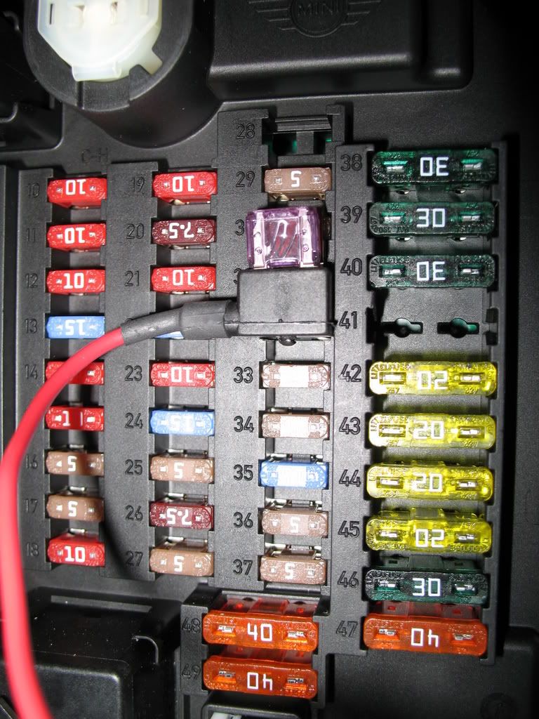
That part you see is a bussman fuse extender, try an auto parts store for that one, it plugs into fuse slot #32. You will also need a fuse to plug into the fuse extender. Try a lower amp fuse, somewhere in the 1-3 amp range should work well. If you look closely at my pictures you will see that there are 2 fuses that plug into that fuse extender, the one in front is the one you will add to protect the timer circuit, the one behind it, that is the original fuse. The other item that you will need and will also likely find at the auto parts store, would be the self stripping electrical tap connector. That's the small red connector you see in the picture with my hand.
Last edited by amazingrando; Jul 20, 2008 at 12:25 AM.
4th Gear
Joined: Feb 2008
Posts: 374
Likes: 0
From: Columbia, SC
That part you see is a bussman fuse extender, try an auto parts store for that one, it plugs into fuse slot #32. You will also need a fuse to plug into the fuse extender. Try a lower amp fuse, somewhere in the 1-3 amp range should work well. If you look closely at my pictures you will see that there are 2 fuses that plug into that fuse extender, the one in front is the one you will add to protect the timer circuit, the one behind it, that is the original fuse. The other item that you will need and will also likely find at the auto parts store, would be the self stripping electrical tap connector. That's the small red connector you see in the picture with my hand.
Auto on Sport Button guy
Joined: Apr 2007
Posts: 702
Likes: 2
From: Portland, OR
Make sure you get the wire tap that I mentioned as you want to avoid cutting and splicing the blue sport button wire, this will allow for easy un-modding should you decide to sell the car someday.
Here is a better pic of what I'm talking about.
http://www.parts-express.com/pe/show...number=082-100
Here is a better pic of what I'm talking about.
http://www.parts-express.com/pe/show...number=082-100

I'm quite keen to try this mod out. My big problem is how do I remove the plastic trim so I can get at the wire. I'm not going to be very popular if I mess this up, or the trim doesn't go back correctly.
4th Gear
Joined: Feb 2008
Posts: 374
Likes: 0
From: Columbia, SC


I can get the fuse box door off alright, I was worried about the rest of the trim around the fuse box, which becomes the door sill trim. Anyway, once I had the fuse box door off, I tugged on trim and it sort of just came off in my hand. The trim piece is attached by a few snap connectors. It goes back on just pushing it till it snaps. (if none of the little white connector posts fall out, one of mine did, I pushed it back in.)
Once I got the trim peice loose, I found the right wire and spliced in a wire. I also attached a ground wire to a metal tab. Then the trim peice snaps back on. After installing the fuse tap I have all the right wires in place. Shorting the button wire to ground turns the sport mode light on.
I did some investigating. The switch switches if its shorted with a 230 Ohm resistor, at that point the wire is at 1.75V. (It doesn't switch with a 430 Ohm resistor, for about 3V.) The wire is supplied by 12V through about 1.3kOhm. When the switch switches it draws about 9mA. The 12V seems to stay on all the time, at least when the interior lighting is on.
That sounds like a logic level input to me, so I thought I could build a little circuit which would do the switching. The relay board people are using seems to be a bit of overkill. I made this:

The components are (with equivalents from RatShack), about $3 worth:
NPN Transistor
10uF Tantalum capacitor
2 10k Ohm resistors
It switches the light on the button on, I assume it'll work for real, I haven't used it for real yet.
Once I got the trim peice loose, I found the right wire and spliced in a wire. I also attached a ground wire to a metal tab. Then the trim peice snaps back on. After installing the fuse tap I have all the right wires in place. Shorting the button wire to ground turns the sport mode light on.
I did some investigating. The switch switches if its shorted with a 230 Ohm resistor, at that point the wire is at 1.75V. (It doesn't switch with a 430 Ohm resistor, for about 3V.) The wire is supplied by 12V through about 1.3kOhm. When the switch switches it draws about 9mA. The 12V seems to stay on all the time, at least when the interior lighting is on.
That sounds like a logic level input to me, so I thought I could build a little circuit which would do the switching. The relay board people are using seems to be a bit of overkill. I made this:
The components are (with equivalents from RatShack), about $3 worth:
NPN Transistor
10uF Tantalum capacitor
2 10k Ohm resistors
It switches the light on the button on, I assume it'll work for real, I haven't used it for real yet.
Last edited by Btwyx; Mar 24, 2011 at 08:38 PM. Reason: Change picture URL

3rd Gear
Joined: Apr 2006
Posts: 258
Likes: 0
From: Philadelphia
On the attached image: (Image incorrectly shows GR/RT as the sport wire, it is the BLUE wire)
"-" and "NO" both go to ground
"+" goes to Fuse F32. Use the Bussman fuse tap, with a 2 or 3 amp fuse. http://www.bussmann.com/images/3c2dc...86ccd13aad.JPG
"C" goes to the sport button wire, Blue wire. You will find this wire on Connector X14272, at the bottom of the fuse panel. You have to remove the plastic sill/fuse panel cover to get to it. See above post for location of this connector.
Set up the module as follows:
DIP Switch:
1 on
2 on
3 on
4 off
Cut J2 (resistor), and set the trimpot to zero (fully counterclockwise)
Start the MINI, and see the sport button turn on by itself.
Disclaimer: Perform the foregoing at your own risk. If you are unsure of how to do this, then don't do it.
Found my problem... when in doubt, triple-check your work. Thanks for a great mod!
Last edited by hopper; Aug 3, 2008 at 11:40 AM.

 thanks

3rd Gear
Joined: Aug 2007
Posts: 201
Likes: 2
From: Southern California (562)
Thanks for the great mod indeed. I can now add it to my list of mods I wish would have come standard from the factory!!

2nd Gear
Joined: Jun 2008
Posts: 85
Likes: 0
From: Frisco, TX
Great information. Thank you to all who contributed. I got mine in and working in no time (well, the actually installation was quick).
Two silly mistakes:
1) I got the wrong size fuse extender. I got one for the larger size fuse, not the mini. Another trip to the auto parts store.
Interestingly, NAPA had never heard of a fuse extender. They had to look it up and still couldn't figure out what I was trying to do. O'Reilly had each size sitting on the shelf. I just didn't catch that there were two sizes.
2) It takes two fuses in the extender. Duh. So, back to the store to get another fuse so that the sport button and whatever else is in F32 will work at the same time.
Now that it's all fixed, I love it! I never would have tried this on my own.
Jeremy
That sounds like a logic level input to me, so I thought I could build a little circuit which would do the switching. The relay board people are using seems to be a bit of overkill. I made this:
...
The components are (with equivalents from RatShack), about $3 worth:
NPN Transistor
10uF Tantalum capacitor
2 10k Ohm resistors
It switches the light on the button on, I assume it'll work for real, I haven't used it for real yet.
...
The components are (with equivalents from RatShack), about $3 worth:
NPN Transistor
10uF Tantalum capacitor
2 10k Ohm resistors
It switches the light on the button on, I assume it'll work for real, I haven't used it for real yet.
After a little experimenting, I came up with the MK1a version of the mod board, which uses a zener diode to stabilise the power signal. It also uses a MOSFET to do the switching, which is what I wanted to use originally, but I couldn't find a suitable one at either Ratshack or Fry's (I got it from Digikey through work). I've made two of them and installed them in both MINIs, they seem to be working for real:

2N700 MOSFET transistor
10uF Tantalum capacitor
5.1V Zener diode
3 resistors, 470Ohm, 120kOhm, 2.2MOhm

Auto on Sport Button guy
Joined: Apr 2007
Posts: 702
Likes: 2
From: Portland, OR
I thought about doing that, considering I do have rather easy access to a lot of the parts and tools needed (I'm a cinema repair tech) so the question becomes how much to charge? and making sure that I don't break any potential NAM guidlines. I would be willing to build up the kit, cut the necessary jumpers and provide some additional instruction if need be.