
Electrical Automatic Sport Button Mod


Coffeeman: I got the circuit board you recommended (Altronix 6062) today and it occurred to me, where do you place this circuit board? Does it tuck in behind the fuse box somehow? Thanks in advance. Mike

Thread Starter
|
4th Gear
Joined: Apr 2007
Posts: 474
Likes: 3
From: Maryland
There should be plenty of room under the fuse box. You also might want to wrap the circuit board in some type of non-conductive foam, to keep it from rattling, or shorting out any of the circuit board tracks.

Auto on Sport Button guy
Joined: Apr 2007
Posts: 702
Likes: 2
From: Portland, OR
** I'm now offering this mod as a pre-assembled kit. Save yourself the time and effort of tracking down all the parts. Let me do it for you! **
PM me for further details
Intallation instructions for my complete kit can be found here: https://www.northamericanmotoring.co...utton-kit.html
* * * * * * * * * * * * * * * * * * * * * * * * * * * * * * * * * * * * * * * * * * * * * * * * * * * * * * * * * * * * * * * * * * *
I now have auto on sport button! thanks to coffeeman and oPossum for all the useful information. I ended up using the timer circuit that coffeeman mentions.
Tools and supplies needed for the job:
Wire stripper/crimper tool (I use Klien tools 1010)
Philips Screwdriver
Wire cutters for J2 resistor
10mm socket
3M Scotchlok 18-22 GA Self stripping electrical tap connector for blue sport wire (auto parts store)
20 GA wire
Bussman BP/HHH ATM Fuse Tap (auto parts store)
Hometech time # 6062
Electrical tape (wrap it around the board to prevent shorting out the contacts)
Directions:
Remove the side panel to get to the bottom right hand side connector, that is X14272. You may not have to completely remove the panel, just pull it aside, I did so in order to give room for my camera, that also required removing the lower seat belt bolt.
Locate the solid blue wire in the bundle and attach the splice connector, use pliers to crimp this connector, you should strip back a piece of 20GA wire to add in to the splice, that will connect up to the common on the relay board. You can test the quality of your splice by simply starting up the car and touching the exposed wire to the chasis somewhere, you should see the sport button light up. Dont' forget to snap the splice cover into place.
Now you can install the board. Make sure that you have the board pre-wired before installation, be sure to test it before you re-install the side pannel, I attached my ground wire under one of the 10mm nuts holding the fuse housing in place.

Wrap the entire board in electrical tape then tuck it away after you re-attach the panel.
PM me for further details
Intallation instructions for my complete kit can be found here: https://www.northamericanmotoring.co...utton-kit.html
* * * * * * * * * * * * * * * * * * * * * * * * * * * * * * * * * * * * * * * * * * * * * * * * * * * * * * * * * * * * * * * * * * *
I now have auto on sport button! thanks to coffeeman and oPossum for all the useful information. I ended up using the timer circuit that coffeeman mentions.
Tools and supplies needed for the job:
Wire stripper/crimper tool (I use Klien tools 1010)
Philips Screwdriver
Wire cutters for J2 resistor
10mm socket
3M Scotchlok 18-22 GA Self stripping electrical tap connector for blue sport wire (auto parts store)
20 GA wire
Bussman BP/HHH ATM Fuse Tap (auto parts store)
Hometech time # 6062
Electrical tape (wrap it around the board to prevent shorting out the contacts)
Directions:
Remove the side panel to get to the bottom right hand side connector, that is X14272. You may not have to completely remove the panel, just pull it aside, I did so in order to give room for my camera, that also required removing the lower seat belt bolt.
Locate the solid blue wire in the bundle and attach the splice connector, use pliers to crimp this connector, you should strip back a piece of 20GA wire to add in to the splice, that will connect up to the common on the relay board. You can test the quality of your splice by simply starting up the car and touching the exposed wire to the chasis somewhere, you should see the sport button light up. Dont' forget to snap the splice cover into place.
Now you can install the board. Make sure that you have the board pre-wired before installation, be sure to test it before you re-install the side pannel, I attached my ground wire under one of the 10mm nuts holding the fuse housing in place.
Wrap the entire board in electrical tape then tuck it away after you re-attach the panel.
Last edited by amazingrando; Jan 21, 2010 at 09:47 AM.

4th Gear

Joined: Aug 2006
Posts: 454
Likes: 5
From: Williamsburg, VA
Thread Starter
|
4th Gear
Joined: Apr 2007
Posts: 474
Likes: 3
From: Maryland
Glad you got it installed & working...pretty cool mod !....now if only I can get the reading lights to come on with the rest of the interior lights, I'll post instructions. I've tugged on the upper reading lamp assembly, but it does not seem to want to come off. This mod only requires the installation of 2 diodes, and connection to the interior light circuit. The diodes prevent the interior lights from coming on if you press the reading light switch(es)
Sport button automated
Coffeeman: I bought the parts and have been following this thread for some time now, finally got some time. Just finished the installation, really cool, works like a champ. Thanks for your effort to figure this out and to share with all the rest of us who would have never accomplished the automation of this function in such a "proper" manner. Thanks and Aloha Mike


6th Gear
Joined: Mar 2007
Posts: 2,009
Likes: 0
From: home
You guys are amazing... I attempt to do mechanical stuff but I could never grasp electrical part of the car. It was very annoying as hell to turn on the sport button every time but it is now my second nature.


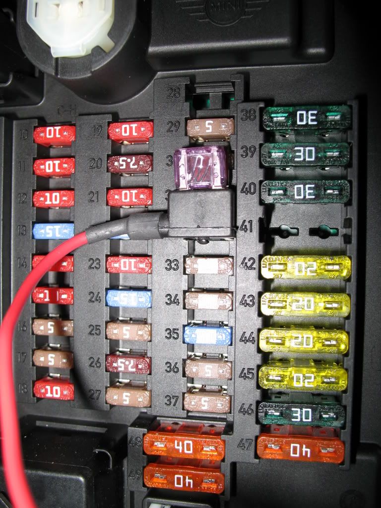
FWIW, on the R53 the add-a-circuit needs to go into the fuse panel 'upside down' in order to properly fuse the circuit.
You can test by pulling the fuse - if the circuit still works, turn the add-a-circuit (Bussman fuse extender here) around.
You can test by pulling the fuse - if the circuit still works, turn the add-a-circuit (Bussman fuse extender here) around.
 We don't have a sport button on the R53. The sprint booster alters the signal from the accelerator pedal to the TPS. Not the same animal.

Yes, after the automatic sport button mod is installed the sport button still works as always. To turn it off, just press the button. The way I understand the circuit on the board it just provides a momentary contact to ground just like the sport button each time you start the car. This is a real "sano" and proper mod. Coffeeman really did us all a huge favor figuring this out, this is a real clean and proper mod that the rest of us non-electrical engineers would have spent one heck of a long time to figure out.
Auto on Sport Button guy
Joined: Apr 2007
Posts: 702
Likes: 2
From: Portland, OR
Yep, what Kukaepe said.
After 9K miles of driving the car this way, I tried turning off the sport button to see how the steering felt, it went from pretty good to feeling utterly horrible, but that is just a matter of preference. So yeah, I'm still very happy with this mod, it's been 100% reliable.
After 9K miles of driving the car this way, I tried turning off the sport button to see how the steering felt, it went from pretty good to feeling utterly horrible, but that is just a matter of preference. So yeah, I'm still very happy with this mod, it's been 100% reliable.
Last edited by amazingrando; Mar 27, 2008 at 10:49 PM.


4th Gear
Joined: Feb 2008
Posts: 374
Likes: 0
From: Columbia, SC
Yo, Boostednorm! I hope you and Bruiser are doing well. Just got a link to this thread. Was it hard? I am thinking of doing this, but not exactly my forte ...
Much easier to do than the Kuda mount for my nuvi 660.
This mod is all done inside the fuse box and you can prewire most everything prior to even going out to the car. If you find you're using the sport button more than without, this mod is for you.
Btw, Bruiser's doing fine... he just went over 3100 miles. 121 of them in a local MINI rally consisting of 30 MINI's and one Mini.
4th Gear
Joined: Feb 2008
Posts: 374
Likes: 0
From: Columbia, SC
Way ahead of mine (now named "Sydney"). 1800 mi. on her. Couldn't make it on the MTTS run from Miami up the east coast, but am meeting up with everyone in Charleston Monday night for some festivities.
Did you and Bruiser run in the rally? Pics?
Did you and Bruiser run in the rally? Pics?

2nd Gear
Joined: Mar 2007
Posts: 100
Likes: 0
anyone know how to use something like this to turn on the fogs with headlights and keep it from cutting out when using the highbeam/flashers?
yes, i understand the purpose of foglights, but i like having it on as a cool factor
yes, i understand the purpose of foglights, but i like having it on as a cool factor

6th Gear
Joined: Jul 2007
Posts: 2,881
Likes: 6

Due to the new guidelines here on NAM, I can't really tell you what I think of fog light users who aren't in heavy fog.

They are designed to be used with the headlights turned off. In dense fog where your headlights are blinding you with glare (I'm mean DENSE fog), you turn off your headlights and turn on the fogs. Being closer to the ground, their beam has a better chance of cutting under the fog and letting you see farther.
4th Gear
Joined: Feb 2008
Posts: 374
Likes: 0
From: Columbia, SC
Here's how: You need to build a simple relay circuit. Parts needed are a SPST 12v relay, 1,000uf 50v Capacitor, 10k 1/2 watt resistor. All available at Radio Shack for under $10.00.
When the circuit receives +12v from either the cigarette lighter circuit, or another switched circuit, the relay latches for 1/2 second, which switches the blue sport button wire to ground. The capacitor charges, which de-engerizes the relay coil, and the resistor bleeds off the capacitor, which keeps the relay coil from energizing again.
The attached diagram shows the relay wiper outputting +12v. Wiring of the relay contacts needs to be changed to output -12v (ground)
If you don't want to build the above circuit, here is one that is ready to go for $35.00: (#6062) http://www.hometech.com/brains/timers.html