
Drivetrain The (definitive) scoop thread

Joined: Jul 2005
Posts: 2,435
Likes: 2
From: Albuquerque New Mexico
The (definitive) scoop thread
Here's a direct comparison of all my scoops, with camera on tripod and similar lighting.

The only scoop missing is the M7 Extreme, which I don't have, but I believe the rear opening to the IC is the same as the OEM, it just gets more Ram effect with a bigger mouth.
I'm next going to look into modifying the diverter to direct the rhs air to the CAI airbox...
The only scoop missing is the M7 Extreme, which I don't have, but I believe the rear opening to the IC is the same as the OEM, it just gets more Ram effect with a bigger mouth.
I'm next going to look into modifying the diverter to direct the rhs air to the CAI airbox...


6th Gear
Joined: Sep 2004
Posts: 5,149
Likes: 0
Here's a direct comparison of all my scoops, with camera on tripod and similar lighting.
The only scoop missing is the M7 Extreme, which I don't have, but I believe the rear opening to the IC is the same as the OEM, it just gets more Ram effect with a bigger mouth.
I'm next going to look into modifying the diverter to direct the rhs air to the CAI airbox...
The only scoop missing is the M7 Extreme, which I don't have, but I believe the rear opening to the IC is the same as the OEM, it just gets more Ram effect with a bigger mouth.
I'm next going to look into modifying the diverter to direct the rhs air to the CAI airbox...
Joined: Jul 2005
Posts: 2,435
Likes: 2
From: Albuquerque New Mexico
Unfortunately, no. I will share with Peter of M7 of course, but I think he's overwhelmed with scoops already, and another one would be too much. This one doesn't require any cutting of the bonnet, just a little bending of the edge of the hole (non structural, no where near the attachment holes.) It would actually work with the DFIC diverter if the RHS air could be directed to the airbox. I am thinking of a new diverter that attaches to the bonnet, and simply feeds directly into the top of the airbox (mine is open, but well sealed to the bonnet.)

Joined: Jul 2005
Posts: 2,435
Likes: 2
From: Albuquerque New Mexico
Shaving the bottom? Yes, and the rest... There's no where to go at the top, but the left side is widened and squared off to allow air to flow to the left of the IC, which normally gets the left-overs (pun intended.) The bottom is completely new, fabricated from a composite with an Al core, and the right side is sloped to miss the rise in the rubber gasket above the radiator. Some minimal bodywork required but *no cutting*, just mild bending of non-structural material.

5th Gear
Joined: May 2005
Posts: 836
Likes: 0
From: Los Angeles
I was reading about IC scoops / ducts in Supercharged by Corkey Bell. The author states that a proper IC "scoop" must have an air inlet area equal to approximately 25% of the IC core area and that anything bigger is unnecessary. It seems that enlarging the air inlet larger than the DFIC would not have an advantage. Please comment.
Trending Topics


Im looking to get a carbon fiber scoop, and was looking at the m7 ram one. With the stock intercooler and diverter, is it worth the extra cash or would i not see much of a difference than a stock version in your opinion?

6th Gear
Joined: Sep 2002
Posts: 2,196
Likes: 0
From: Hampton, VA
Probably the nicest looking aftermarket scoop.
Joined: Jul 2005
Posts: 2,435
Likes: 2
From: Albuquerque New Mexico
Yes, the Ram scoop is particularly effective compared to the stock scoop. As you can see from my photos, it's wider and taller, and looks great too! I'd recommend a diverter mod to extend the front skirt of the stock diverter to catch all the air that goes in, which is a relatively easy mod. Email me for details.
cheers,
cheers,

Joined: Jul 2005
Posts: 2,435
Likes: 2
From: Albuquerque New Mexico
Tony: I started with a Ram intake, and removed about 2" from the lower lip tapering to the top lip on either side. Then cut a thin Al sheet and bent to shape, epoxied and built up to thickness, etc. It is essentially the same shape as the DF scoop, only that the bottom lip sits lower and the sides are wider.

Bitchen photos...
can you do the same with side views?
And excellent work.....
I think the comment by Corky talking about relative opening sizes ios a comment that is better for "standard" geometries, like a front mount. The relative areas has to do with the fac that the IC only flows air through a smaller percentage of it's total face area. I'd take the "25% rule" and increase it if the flow isn't perpendicular to the opening (like our hood scoop, with the air running over the surface of the hood) and for flow paths that aren't straight on (Minis are a bit convoluted but not too bad here).
The trade off is between cooling and drag. If you stuff so much air eventually you will loose more from drag than you do get from cooling. But driving style effects this a lot as well. Very high speeds would bias to drag reduction, and very low speeds would bias to larger openings....
Like all things cars, there is no "right", just guides for the eye to use as a starting point, and a lot of black magic!
Matt

Nobody can patent that concept...
FWIW, we used to discose appications of our products in conferences so some of our more aggressive customers wouldn't patent the application, and leave us with a limited market..... IP for the masses!
Matt
Joined: Jul 2005
Posts: 2,435
Likes: 2
From: Albuquerque New Mexico
I took a look this morning regarding the diverter for air to the airbox. There's 2 choices: (i) I fix it to the engine -- this means it's fixed to the diverter connected to the intake manifold, goes as a closed rectangular-ish tube over the IC-out horn, and then joins the airbox with a flex joint, or (ii) I fix it to the bonnet -- this allows a fixed connection to the scoop, uses the bonnet as one of the 4 sides (the top) of the rectangular tube, and then a flexible rubber or foam seal to the top of the airbox. I'm leaning toward this since it means the diverter can be larger, and since the airbox is fixed, the seal to it would not require significant flex. Since this is for the DFIC, and Randy is on record as saying he disagrees with the DFIC design, I doubt he'd be too concerned about my pitiful attempts. And I have no intention of making but one...
Bart: I have seen photos of the Uber--it seems to have a pitifully small opening at the rear since it's designed for stock downdraft ICs. And I like the shape of the Ram/DF scoops that Joel crafted--having worked on one for the last 2 weeks, I am intimate with the curves he shaped into that thing--he's truly an artist!
Bart: I have seen photos of the Uber--it seems to have a pitifully small opening at the rear since it's designed for stock downdraft ICs. And I like the shape of the Ram/DF scoops that Joel crafted--having worked on one for the last 2 weeks, I am intimate with the curves he shaped into that thing--he's truly an artist!
Bart: I have seen photos of the Uber--it seems to have a pitifully small opening at the rear since it's designed for stock downdraft ICs. And I like the shape of the Ram/DF scoops that Joel crafted--having worked on one for the last 2 weeks, I am intimate with the curves he shaped into that thing--he's truly an artist![/quote]
Thanks Dr Phi, I say blushingly.
Thought I might share my DFIC scoop now.

Thanks Dr Phi, I say blushingly.
Thought I might share my DFIC scoop now.
Me too
DrPhilGandini,
Thanks for the pictures, very precise.
I have a working model of a different IC air diverted for the stock IC that seals to a new bonnet piece I made up. From what I learned from this one I have the final design in mind and will probably make another one now that I have all the dimensions. Due to the offset of the IC I left the right side open and was considering routing that air into my air box too, but.
Changed my mind about that since modifying a stock air box that now gets plenty of cool air from the front duct and is sealed to the cowl area with at least a 4x larger inlet in the base to the cowl.
Anyway the open area on the right side is allowing air to blow over and under the exit duct of the IC carrying heat and air that has just passed through the IC. I have evidence of this due to deposits on my just cleaned red Alta hose adjacent to the underside of the IC. It appears to be functioning as an eductor, pulling air from under the IC as it blows by while providing a bit of cooling to the exit duct. If the insulating of the bottom side of the OEM IC from radiant heat is a proven factor then that could be coupled with this Mod for even more efficiency.
Next I need a stock air scoop to cut up and model on, anyone got a spare for cheap?
By the way, if nobody reinvented the wheel can you imagine what you would be riding on today?
6th Gear
Joined: Sep 2002
Posts: 2,196
Likes: 0
From: Hampton, VA
DrPhilGandini,
Thanks for the pictures, very precise.
I have a working model of a different IC air diverted for the stock IC that seals to a new bonnet piece I made up. From what I learned from this one I have the final design in mind and will probably make another one now that I have all the dimensions. Due to the offset of the IC I left the right side open and was considering routing that air into my air box too, but.
Changed my mind about that since modifying a stock air box that now gets plenty of cool air from the front duct and is sealed to the cowl area with at least a 4x larger inlet in the base to the cowl.
Anyway the open area on the right side is allowing air to blow over and under the exit duct of the IC carrying heat and air that has just passed through the IC. I have evidence of this due to deposits on my just cleaned red Alta hose adjacent to the underside of the IC. It appears to be functioning as an eductor, pulling air from under the IC as it blows by while providing a bit of cooling to the exit duct. If the insulating of the bottom side of the OEM IC from radiant heat is a proven factor then that could be coupled with this Mod for even more efficiency.
Next I need a stock air scoop to cut up and model on, anyone got a spare for cheap?
By the way, if nobody reinvented the wheel can you imagine what you would be riding on today?
Thanks for the pictures, very precise.
I have a working model of a different IC air diverted for the stock IC that seals to a new bonnet piece I made up. From what I learned from this one I have the final design in mind and will probably make another one now that I have all the dimensions. Due to the offset of the IC I left the right side open and was considering routing that air into my air box too, but.
Changed my mind about that since modifying a stock air box that now gets plenty of cool air from the front duct and is sealed to the cowl area with at least a 4x larger inlet in the base to the cowl.
Anyway the open area on the right side is allowing air to blow over and under the exit duct of the IC carrying heat and air that has just passed through the IC. I have evidence of this due to deposits on my just cleaned red Alta hose adjacent to the underside of the IC. It appears to be functioning as an eductor, pulling air from under the IC as it blows by while providing a bit of cooling to the exit duct. If the insulating of the bottom side of the OEM IC from radiant heat is a proven factor then that could be coupled with this Mod for even more efficiency.
Next I need a stock air scoop to cut up and model on, anyone got a spare for cheap?
By the way, if nobody reinvented the wheel can you imagine what you would be riding on today?
I had posted this a while back.
I made a temp duct that lead from the front radiator support and fed under the IC.
The thought was that blowing air under the IC would help.
It failed quite miserably.
My thinking is this disturbed the exit flow under the IC. In effect creating a shear that prevented good flow.
Yep, I agree to that!
"My thinking is this disturbed the exit flow under the IC. In effect creating a shear that prevented good flow."
My point being I want a larger scoop to run with an OEM IC and my diverter system, DrPhilGandini is working the scoop project.
"My thinking is this disturbed the exit flow under the IC. In effect creating a shear that prevented good flow."
My point being I want a larger scoop to run with an OEM IC and my diverter system, DrPhilGandini is working the scoop project.

3rd Gear
Joined: Mar 2006
Posts: 228
Likes: 0
just got my DFIC. what a piece of art! unfortunately the same thing cannot be said of the fiber glass scoop (am I ****?)
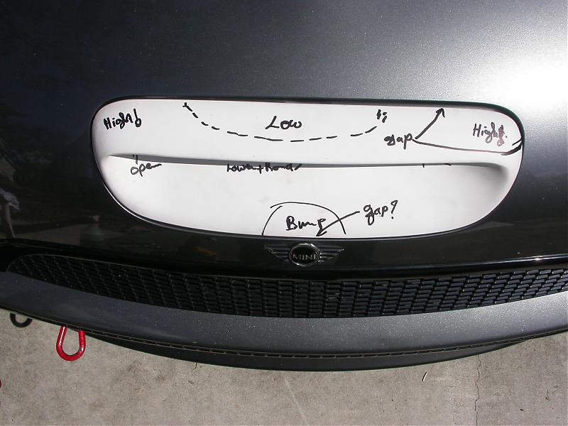
I like my mods to look OEM so out comes the tape, putty and sand paper. OK fit looks better...

now... seems to me that the opening could be bigger?

So here we go: some cutting, some glassing ,some fairing and....

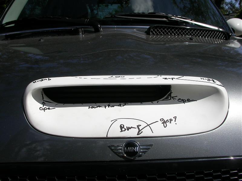
clean lines, maximum opening, just my interpretation of the scoop

But then... after reading this thread, and with the juices flowing, i was thinking of that left side and how to get it to the air box...

hmmmm... so close to the OEM intake tube!

could be something like this... then again... just my brain on a MINI-high
sorry for the gigantic pictures posting... my darling daughter was helping me with it but we couldn't figure out how to attach more than three pictures as the first three appear. :impatient
I like my mods to look OEM
so out comes the tape, putty and sand paper. OK fit looks better...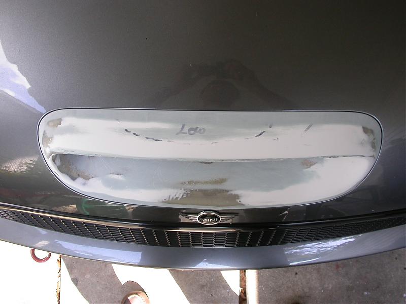
now... seems to me that the opening could be bigger?
So here we go: some cutting, some glassing ,some fairing and....
clean lines, maximum opening, just my interpretation of the scoop
But then... after reading this thread, and with the juices flowing, i was thinking of that left side and how to get it to the air box...
hmmmm... so close to the OEM intake tube!
could be something like this... then again... just my brain on a MINI-high
sorry for the gigantic pictures posting... my darling daughter was helping me with it but we couldn't figure out how to attach more than three pictures as the first three appear. :impatient