When you click on links to various merchants on this site and make a purchase, this can result in this site earning a commission. Affiliate programs and affiliations include, but are not limited to, the eBay Partner Network.
Like any military campaign good supply line is crucial. My advance on the front has came to a screeching halt until more parts show up. Blame it on the general for lack of planning and foresights.
The header work is held up by the oxygen sensor heat sink bung extension. I think I will try to get ahead by removing the header so at least I can stare at the challenge, and warming up to the dreaded welding that I would need to do myself.
If I am very motivated, I might also install the braided brake lines for the tiny rear toy brakes so they look cool. I can't install the racing front pads until the titanium shims arrive and there is no supply line update. Someone's head got to roll.
My neighbour remarked yesterday that the Mini spends more time up on jack stands than down to earth.
cannot help but to notice the post cat sensor has a deeper plunge over the pre cat one; note the bend of the header at the pre-cat to favor it for clearance as it is tighter on that side
I removed the oxygen sensors to protect them from damage. It crosses my mind if there is any benefit two swap the two sensors as the upstream one gets all the heat and has a much tougher job.
Mind if I ask why the new brake parts? Pistons, seals and dust shields (maybe)?
The BP-10s were threatening to incinerate Mini at the track. Multiple folks told me they saw sparks and I smelled brake lining overheating. I kept getting the blue flags and I checked only to found no one was at my tail. I passed off one HPDE that I really wanted because of waiting for the BP-30s.
The other caliper parts are to head off thermal OD. They are upgrades that are not visible, so not conspicuous consumption but they cost a bundle.
I went ahead and installed the braided lines for the rear brakes. I bought these from ECS and they are very well made and reasonably priced. I was hoping there will be no unforeseen complications, like that I encountered with the Wilwood ones for the front.
to remove the stock line, start from the hear brake line end with a 11mm wrench; I used this nifty little plastic cap to stop the brake fluid from dripping
Once the connection to the hard line end is separated you can remove the line from the caliper with a 14mm open end wrench.
once the stock line is out I compare the end fittings with the ECS ones and they look to have the same features so should be no surprise
this end interface to the hardline and retained by the bracket is most important; not like the cheesy Wilwood one
the most important parts of the line are the quality rubber grommet and the anti-chaffing overlay and ECS done an amazing job
the rubber grommet is very substantial and sits securely in the damper cradle; I had to use soap water to help it slip into the cradle and still took a bit of force
the fitting on the hard line end is captived by the stock bracket and spring clip exactly like the stock line
The installation was the easiest of any aftermarket parts I've ever done. This is a winning product at very reasonable price. No surprises and the quality is everything I expected.
The part markings on ECS line piqued my interest. A bit of internet detective work suggested "BQUSA" is Brakequip, which makes all sorts of brake line products, including the cheesy universal clips that came with the expensive Wilwood braided lines. SAE J1401 is an OEM must meet standard.
cheesy Wilwood braided line with it **** universal clips and poor quality rubber grommets
The addition of the bung for the WB sensor has no room for the slightest error. I had tried to fix the location in 3D space and that proved to be very difficult as you cannot sight it from the engine bay or crawling under the Mini. even if marked the proper location, you still have to have the angle just right. We put the header back into position to try fix the spot and we ended up having two diverse spots, let alone the angle.
two different spots from two sighting/feeling
There is only one chance to get this right, and failure is not an option for this battle so no blitzkrieg for this general.
I modified my stock header, cut it and remove the "precat" cat and reweld it up, gives you a lot more room and freedom to mount the wideband bung.
it'll be louder, never threw a code from the little I read on it the precat was added for cold start emissions
I would have done that have it not that we care about our planet.
For the unforeseeable future I plan to keep my Mini dual duty, and that makes it so much more challenging and I am fine with that. Being a beast, Mini will never go onto the Noah's ark. A good Mini is a responsible Mini and Desire is not about to be an all-badass track animal yet. At least Desire can dream to be one.
Desire will never desire to be a doomed passenger of this; Desire believes in scientific proof and this is not one
Even before I pulled the trigger to buy the $65 Innovate HBX-1 I read the comments on Amazon. Not satisfied I went to Innovate Motorsports to try find the dimensions, and instruction for it. They only hit I could find on their site is their online store. The link was dead saying the store is closed. I went ahead and ordered one from fleaBay (always faster than shipped by Amazon) and it arrived.
Unlike the product photos it is shinny stainless steel as I already figured out. It is beautiful. So beautiful that you can use it as a modern jewelry, though not a good idea for earrings.
I went and do a test fit on the bung that came with the MTX-L A/F gauge. Immediately something looks wrong. Where is the hole that I am suppose to index to face the exhaust wind? Clearly the nose of the HBX-1 heatsink bung extension is too short.
Reading the piece of paper instruction it ships with, it says it is designed to use with a 18mm long bung. OK. I did try to find the dame spec but you didn't provide one online.
It gets better. I pulled out my ruler to see if the common 1/2" bung is 18mm, so I can order one and wait a few more days. Well 18mm is more like 3/4". What is wrong with the picture? If I am dumb enough to follow the instruction and get an 18mm bung, the hole on the side will still be covered by the bung. Carefully measurement shows that it should be no more than a 1/2" long bung, which is closer to 12mm. I am convinced they have a team of monkeys doing product development.
The stock pre-cat bung is 1" long too. I feel a bit cheated. With a shorter 1/2" bung the temperature will be higher than the 1". So buying this heatsink bung I have to increase the temperature to get the benefit. Makes no sense.
I am confronted with the dilemma to or not to cut down the 1" bung to 1/2". It will be on the header forever.
Finding these surprises is why I have a habit of test fitting and checking everything before proceeding. Someone can always throw you a curve ball.
In moments of weakness yesterday, I almost went and order a 1/2" bung had it not because they are all too expensive. I tried to think what is the best way to cut my 1" long bung into 1/2". The metal chop saw was my first thought but it will not work as the built in clamp to the cutting disc is more like 1/2" distance. Next thought is to use the 4 1/2" angle grinder fitted with a cutting disc but I hate the noise and not too thrill of cutting off a finger even on the less useful left hand.
As the day worn on, I thought to myself, we all became soft in the age of power tools. Whatever happened to the hacksaw? The bulk of the substantial bung is very misleading and if it is SS it can be more difficult. I have a very good made in USA hack saw and I don't see why I can't.
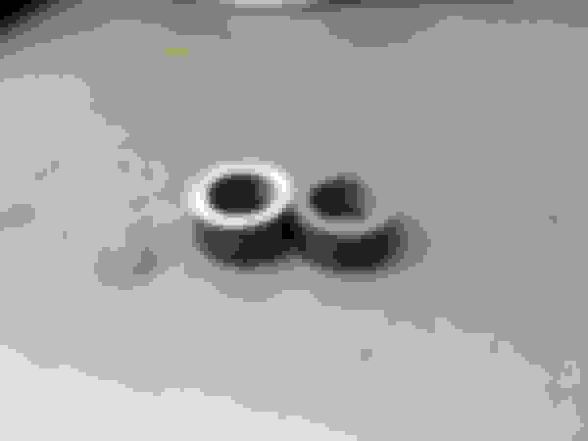
Clamped it into a vice and with some care a few minutes later I have two 1/2" bungs.
it is such a pleasure to manually cut with a good hacksaw
pretty equal size two 1/2" bungs
followed with a bit of filing and sanding to remove the burrs
next I clamp them into the vice and torque the heatsink adapter down and made an index mark with the trusty hacksaw
here is the inside view of the heatsink bung; you can see how it promotes swirling of the gas for the sensor
I have no idea of this $65 investment will save the WB sensor from thermal OD. My need for it is for finding out if Mini's motor is running too lean with the 15% pulley without tune, and next for tuning with bigger injectors. Should the WB sensor too sensitive to heat at this location, I will just remove it as my need for it is just tuning.
I am going to this length as I want to know the A/F ratio with and without a tune, and the variable of the injectors etc. The prices that I am willing to pay for these important information.
Last edited by pnwR53S; 04-24-2018 at 12:43 PM.
Reason: obscure sensitive personal information
Still more gift showing up. So much so that I scratch my head wondering what could it be such a big and heavy box.
It is more slow down parts for Mini, as consumables.
Only one rotor? That's right. The lowest price I found on fleaBay only has 1 left with free shipping so I snapped it up. It said 1 sold and 1 left. A penny saved is a penny earned.
Guess what, the same outfit has another one the next day. Again it says 2 sold and only 1 left. I snapped that one up too. I would checked again later and the listing is up and this time says 3 sold and only 1 left... You know the rest.
the supply line of this campaign is moving well now
are the internal vanes on those directional? I have the slotted and a set of fancy J hooked from apa racing, both have the internal vanes setup so they only work on one side of the car, sucks because I have to haul 2 spares to the track
I just read about this Chinese post processing app. In the country it is expected that you use it to make you and your friend more photogenic in those selfies before you share in social media. It is said on average people spent 45 minutes on their selfie, and 1.5 hour on one with friend. The Meitu app. If the Mini photos you took with the smartphone mostly look crappy, here is the app for you.
I am sold by these results; the two handsome boys must be high school buddies
Wow! locating the bung is infinitely harder than I imagined. There is no room for error. Not much progress to show for at this point.
I came up with this mockup so I can transfer the orientation of the planned WB sensor off the car
I have to put the header back in place onto the head to find the exact location and pointing of the aluminium mockup of the sensor
Then I carefully took the header off the car. Now how to preserve this location since I have to remove the mockup, drill a big hole, and then weld the 1/2" bung at the location at the correct angle. As the surface there is a vase shape setting such a short bung is very challenging.
I use the trailer bed as a poor man's granite flat and made some not so hard points for indexing - out of deck screws
these two screw heads describe the pointing of the mock sensor
Next is to remove the aluminium sensor mockup and bore a big hole. That stainless steel is thick and extremely hard.
After the hole is drilled, the angle of the surface is way off; off by like 30-degree. My thought is to pound the high side down to correct the angle. I check the construction of the precat. Fortunately it is made of folded metal cat cells and not ceramic. That means it can take some pounding without damaging the pre-cat. I also being careful not to drop metal shavings into the cat cells when I drill the big hole.
pounding the high side around the hole took some good aim of a 1 1/2 ball peen hammer with many resolute strikes; no brass hammer used here
Before I did the pounding to shape the header surface there was 1/4" of maximum gap between the bung and the header surface because the curve there is so severe. After the poundings the maximum gap is about 1/8" which the weld bead can bridge.
I put the header back onto the poor man's granite flat to check
the aim of the bung is just about perfect first time around
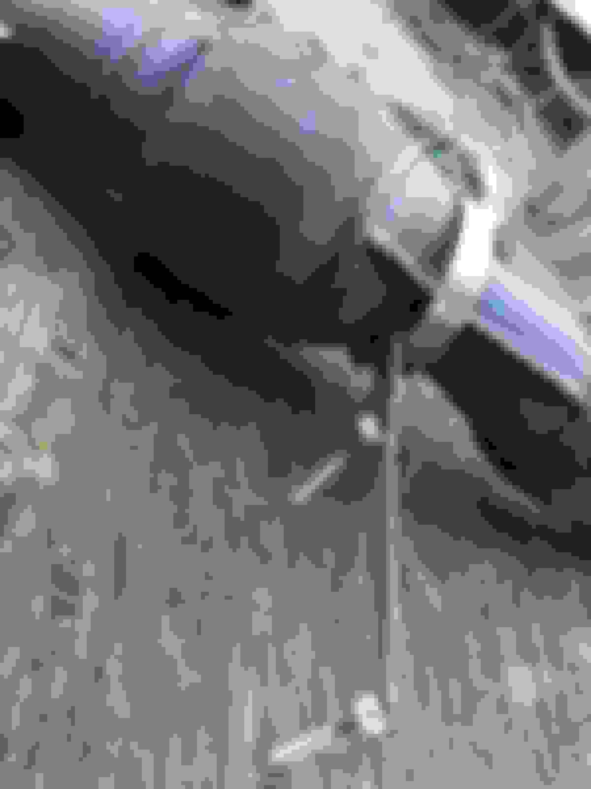
In this photo I put in two red lines to show the split of the clearance between two surface where the WB sensor must reside
The next step is to tack weld the bung onto the header, and then put the header back into position to do the final check before welding it up. At least that is the well laid plan. There is very little to show for, but the most challenging steps are done. The only thing that I dread is the welding as my welding skill sucks.
An interesting observation of the vase shape pipe between the collector pipe section and the pre-cat. The two folded and welded seams are gussets to strengthen the section before the flex joint. The vase sharp must be designed with computer fluid flow modeling to achieve the best laminar flow and even gas distribution over the catalytic conversion cells. There are so much more than what first meet the eyes. There are many subtleties in such a compact header with two cats, and two oxygen sensors. The whole thing is only 36 inches end to end.
What is amazing is the upstream sensor lasting so long when it is exposed to hellish infernal - being so close to the collector pipe.
Looks like some tedious work. While you’re in there, check the condition of the weld on the pre-cat where it always cracks. It would suck to have to pull the header out again if it fails.
Looks like some tedious work. While you’re in there, check the condition of the weld on the pre-cat where it always cracks. It would suck to have to pull the header out again if it fails.
With the repair the header is now stronger than new. The failure occurred near the weld bead. With all the good intentions of the design evidently there is this weak point from manufacturing. I suspect is the cold draw of the stainless steel pipe to shape into the cat resulted in a thin and brittle segment that tends to fracture.
It had been hot, dry, and windy here like August . The pollen counts have been going through the roof with strong East wind. I managed to squeezed in a few hours of work in late afternoon. The bung is welded. This is my first attempt to weld steel onto stainless steel. Very interesting experience as the steel bung melts much easier the stainless steel header despite it being quite substantial.
I first tack welded the bung onto the header. Then put the header onto the cylinder head to check. Not bad, so I went ahead and welded the bung on good. The weld is far from pretty, but it sure won't fall off. I tight to be careful not to leave behind a pin hole, as even a small one can affect the reading accuracy.
I first tack welded the bung onto the header using this improvised fixture - my trailer bed
The welding generated so much heat that the bung is deformed slightly and the thread became very tight as I tried to screw on the stainless heatsink bung extension. You can buy a bung chaser tap to tidy it up but I wasn't going to wait for one to be shipped so I lubricated the thread really good and slowing work the heat sink bung extension into it. I threaded it back and forth and oiled it more so not to shear the stainless steel extension off. While it looks quite stout the section where the fins are machined is the weakest part. I managed to get it threaded tight.
I was concern that I might burn the house down with a few stray welding ambers as the pine needles are kindling dry
I love this Harborfreight auto dimming welding helmet - $34 well spent; the trailer bed with dried pine needles is my welding fixture and table
All good. No fire truck, and the hardest part of this project is over.
I didn't have a good handle on the EGT of the Mini, nor much of what range is common with pressurized induction engine. I remember this thread which is very helpful. Around 900C at the collector. With this I pondered on what could be at the hexagon of the WB sensor now sitting on the heatsink extension and in the (outside) wind. Note that it now would be much sheltered from the direct high speed stream of the exhaust gas.That in itself cuts down a lot of thermal energy reaching the sensor. The biggest contribution of temperature rise would be the conducted heat through the stainless body of the extender.
in this photo one can see the deliberate thin wall at the finned segment


 04-22-2018, 09:17 AM

 I can't install the racing front pads until the titanium shims arrive and there is no supply line update. Someone's head got to roll.


 Multiple folks told me they saw sparks and I smelled brake lining overheating. I kept getting the blue flags and I checked only to found no one was at my tail.


 At least Desire can dream to be one.