
brake system explained


Thread Starter
|
3rd Gear
Joined: Apr 2013
Posts: 199
Likes: 27
From: nj
brake system explained
can someone please tell me how the old brake system works? i know and understand the modern brake system and assembly perfectly fine. i know all about the booster and stuff like that. but i cant seem to find not even a diagram of the classic coopers brake system. i would like to know and understand how it works. how is the brake pedal attached and how it is routed. does anyone have the explanation of the system?
thank you.
p.s. again i understand the modern system and abs if its all the same then just say its the same but i highly doubt that.
thank you.
p.s. again i understand the modern system and abs if its all the same then just say its the same but i highly doubt that.

1st Gear
Joined: Oct 2013
Posts: 29
Likes: 0
The classic mini has a much simpler brakesystem than the current mini. No ABS-pump, no vacuum enhancer, just a master-cylinder, a brakepressure divider and the brakes themselves.
The system is divided in two "circuits", which divide braking diagonally over the wheels. The mastercylinder is of the twin type which integrates two mastersystems in one housing and so with two exiting brakelines.
The two sepparated circuits are connected through a balancing valve wich usually is mounted on the rear subframe. This balances the presure between the two circuits so that left and right have the same brakepressure.
All in all a simple system.
Older mini's have drumbrakes all arround with single brakeculinders in the back drums and double in the front. Coopers and cooper S. have discbrakes in front with a simple two sided single piston setup.
Some cooper s have a. Optionally vacuumpump for the servoassisted system. This is mounted on top of the clutchhousing.
Later mini's have discbrakes in the front. Therefore the wheelsize went up. Stil no standerd servoassist though.
Is this enough information for you?

OVERDRIVE
Joined: Jul 2006
Posts: 7,037
Likes: 283
From: Melbourne, FL
if you have two cans that look like this

one is clutch and one is brakes
if you have ONE of thise cans it is clutch
and you then probably have something like this
 or this
a single circuit was used on early models with the dual circuit arriving in 75 using the item on the bottom until approx 1980. The item in the middle appeared with the disk brake servo assist systems
See parts descriptions at 7ent.com
http://www.7ent.com/products/brake-m...m-gmc0167.html
cars that have had Cooper or Cooper S disk systems retrofitted often fitted the later servo system as well .... that's what you'd see on my 79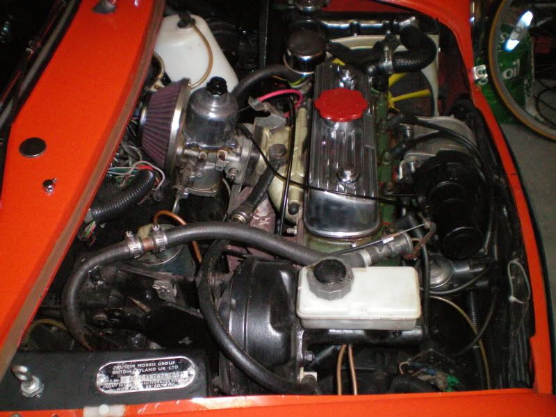
one is clutch and one is brakes
if you have ONE of thise cans it is clutch
and you then probably have something like this
or this a single circuit was used on early models with the dual circuit arriving in 75 using the item on the bottom until approx 1980. The item in the middle appeared with the disk brake servo assist systems
See parts descriptions at 7ent.com
http://www.7ent.com/products/brake-m...m-gmc0167.html
cars that have had Cooper or Cooper S disk systems retrofitted often fitted the later servo system as well .... that's what you'd see on my 79

Thread Starter
|
3rd Gear
Joined: Apr 2013
Posts: 199
Likes: 27
From: nj
usually cars that are lhd and rhd have the brake booster on the side of the steering wheel. but the coopers always place their booster on the right side even though the driver can sit on the left side. how is the pedal connected then.
1st Gear
Joined: Oct 2013
Posts: 29
Likes: 0
My Mini Cooper 998 MKII from 1969 didn't have Servoassisted braking. therefore the brake-master cylinder was on top of the pedals, next to the clutch one the left ( lhd). My Mini 1000 Van (1973) also had both cylinders on the left. My Mini 1000 (1979) had the same setup. My mini Jetblack ( 1982? or 1984? not sure) and with disc brakes had servoassist the pedal was connected by connection rods to the master cylinder on the right.
But.... I've seen more than one Cooper S MK2 and newer with vacuum servo assist. these had the master cylinder on the left but where hydraulically connected to the vacuum pump on the right.
So there ar ea lot of options
But.... I've seen more than one Cooper S MK2 and newer with vacuum servo assist. these had the master cylinder on the left but where hydraulically connected to the vacuum pump on the right.
So there ar ea lot of options
Trending Topics
OVERDRIVE
Joined: Jul 2006
Posts: 7,037
Likes: 283
From: Melbourne, FL
interesting observation
I checked Haynes and the Mini workshop manual for 69 thru 76. The Haynes makes no mention as to side or the connection of the pedal. Workshop manual mentions the servo in the Cooper and S configuration but again no mention of side or connection that I found in one pass
mine is a rhd . . . and not a Cooper
Thread Starter
|
3rd Gear
Joined: Apr 2013
Posts: 199
Likes: 27
From: nj
seems like their are a lot of different setups that happened. the lhd and rhd did a big role on how the cylinders were activated using linkage. someone will make a chart any second i know it.
OVERDRIVE
Joined: Jul 2006
Posts: 7,037
Likes: 283
From: Melbourne, FL
I've listened to discussions about this issue at car shows, in a different context: swapping from a right to left side drive.
"it is easy, altho you must move the servo and change the steering rack..."
which sounds good, but when I look at my engine compartment and those of other cars I have pictures of there just ain't ROOM for the servo on the other side! NO WAY . . .
Looking at my same picture, the servo would need to fit between the rad and the fan??? My inner fenders are removed so on a stock car even LESS room. I'm gonna put this on my 'look for' list for an up coming Brit car show and maybe flip thru the 2 years worth of MiniWorld back issues I have sitting here .... I've never paid much attention to lhd Minis . . . Now you've got me wondering . . .
***********************
from my secret source who I trust 80% (having been BURNED by 'experts'):
Putting aside the Coopers S remote servos, yes all of the inline servo cars have the brake servo/master on the right side. The LHD brake pedal goes across the car and has linkage up to the bellcrank. There are several pieces that go with the pedal, so if you are swapping to LHD you have a few bits to collect.
Look at the diagram: https://www.somerfordmini.co.uk/eshop/i ... page&id=58
Last edited by Capt_bj; Feb 24, 2014 at 02:48 PM.

Thread
Thread Starter
Forum
Replies
Last Post
igzekyativ
MINIs & Minis for Sale
34
Jul 16, 2020 12:54 PM
Mini Mania
Tires, Wheels & Brakes
0
Aug 26, 2015 10:28 AM
Mini Mania
Tires, Wheels & Brakes
0
Aug 26, 2015 10:13 AM
Mini Mania
Drivetrain Products
0
Aug 25, 2015 09:18 AM