When you click on links to various merchants on this site and make a purchase, this can result in this site earning a commission. Affiliate programs and affiliations include, but are not limited to, the eBay Partner Network.
Stock Problems/IssuesDiscussions related to warranty related issues and repairs, or other problems with the OEM parts and software for MINI Clubman (R55), Cooper and Cooper S(R56), and Cabrio (R57).
I need some diagnostic help with a 2009 Mini Cooper Clubman S, with about 130,000 miles. I pulled the engine to change the timing gear, clutch, and walnut blast the intake valves, and got it all back together. The car runs, but while idling it will occasionally miss, and the miss gets worse at high rpm. So far I have smoke-tested for vacuum leaks (none), swapped MAF sensors (no change), throttle body (no change) and confirmed that the fuel system is working correctly. I’m at the point now where I have to start investigating the wiring harness between the MAF and the ecu.
I get a 2B51 code, which suggests that the signal from the mass air flow sensor to the ecu is bad. | hooked an oscilliscope up and tested as suggested by Pelican Parts, and the incoming signal from the ecu looks good, but the signal from the MAF to the ecu is very slow, which may be what is triggering the 2B51 code. The ground at the MAF looks good, but the voltage is low. Pin #1 is supposed to be 12V, but I get 8V. I’m wondering if the low voltage could be the cause of the error at the MAF.
I checked continuity between the ecu and the MAF, and the ground and power lines ring connected. I next measured the voltage between the battery negative terminal and the pins on the MAF and ecu.
This is with the engine running, as I get 0 volts with the engine off.
Pin 1: 1.9V at ecu, 14.3V at MAF
Pin 2: 0.01V at ecu, 0.01V at MAF
I disconnected pin 4 and repeated the measurements:
Pin 1: 14.4V at ecu, 14.4V at MAF
Pin 2: 0.008V at ecu, 0.009V at MAF
Interestingly, with the engine running and all 4 pins connected the ground (pin 2) still tested positive for continuity, but power (pin 1) no longer had continuity. Continuity was restored when I disconnected pin #4 (MAF signal to ecu). It looks like the return signal from the MAF (pin 4) is lowering the voltage from the ecu on pin 1, but I can’t figure out why it is then normal at the MAF.
Pin 1 seems to be shorted to pin 4 in the connector. Replace or repair the connector.
Interesting. How would that happen? By visual inspection the connector looks fine. I can open the snap cover and just barely see the pins, although I haven�t figured out how to release the outer housing from the inner structure that binds the pins themselves to get a better look. The pin 1& 4 don�t ring with continuity when I test with my multimeter. But I can see if that plug is available.
Edit: Give details on how you are doing the voltage tests.
For voltage test, at the MAF I put breakout leads between the pins of the MAF and the pins in the MAF plug, and looked for voltage from the lead.
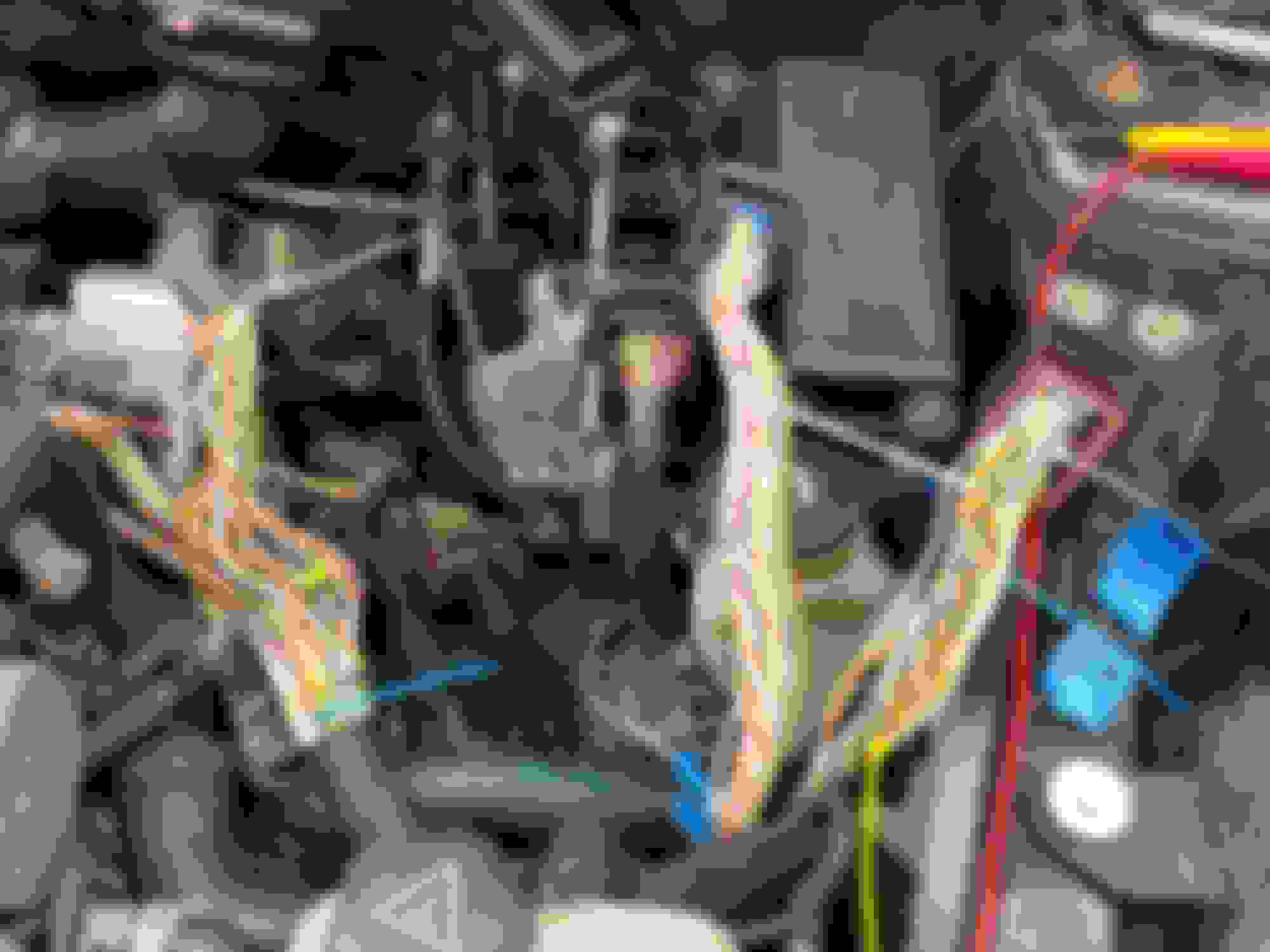
At the ecu I could not back probe the pins so I had to use a puncture electrode on the wire coming out of the ecu plug in the wiring harness. In the attached pic the pin circled in yellow rang for connectivity with pin #1 at the MAF, and the pin circled in blue rang with pin #2 ground at the MAF. So I reconnected the plugs to the ecu and tested voltage from the wires coming out of the plug.
Start here^. The vastly different readings of 1.9V at ECU and 14.3V at MAF tell you that the pin 1 wire does NOT have full continuity between the ECU and MAF. Check for poor electrical contacts between the installed leads and the pin 1 wire and MAF and/or ECU connector.
Last edited by Maybe, maybe not; Aug 11, 2024 at 11:25 AM.
Okay, the short answer is it looks like the MAF voltages are okay, but I still don�t know why I�m getting the MAF signal error code.
The long answer: Your suggestion to trace the wire was a good one. It turns out the wire at the ecu that I thought came from the MAF sensor was incorrect. The wire from that pin did ring for connectivity to the MAF sensor, but the wire went under the intake manifold and then must have returned to the sensor somewhere else in the harness. I identified the wire that supplied 12V at the MAF sensor plug and traced it back to the ecu. Now when I test with the car running I get battery voltage at pin #1 and at it�s sending wire at the ecu. This holds true if pin #4 is disconnected or not.
Pin #3 is 3V, and pin #4 is 2.6V. These values look approximately correct, as they should be 2.5V at both pin #3 and #4.
But now I�m left with the question, what next to test?
To verify your voltage test results, does your scan tool read live MAF data? If scan tool readings match your test results, one possibility is a bad DME.
Last edited by Maybe, maybe not; Aug 11, 2024 at 03:59 PM.
After tracing the wiring and confirming the correct pins, I noticed that the MAF error went away when I was running test jumpers between the pins on the MAF and the pins on the plug. The MAF was new so I suspected the plug might be bad. I got a new plug and pins and the problem seems to have gone away.