When you click on links to various merchants on this site and make a purchase, this can result in this site earning a commission. Affiliate programs and affiliations include, but are not limited to, the eBay Partner Network.
So now, I know the motor is not working, however I do feel a vibration or a buzzing / pulsing on the temp door motor when turning up the heat on the control panel.
But get this, I pulled the motor and applied 9volts and ground to two pins (I'll post a pic), and the motor / lever moves as expected. It appears to be working.
Based upon these observations, do you get a sense the motor is struggling to open the doors ......?
Few things jump out at me. But again, I'm not really good with electrical...
The mixing plug, first plug above, has two grounds. Why is that necessary? Normal?
Maybe pin 4 is shorting to ground (notice its voltage is similar to pin 2 and 6, the confirmed grounds). Would it not then have continuity to ground?
If both pin 2 and 6 have continuity to ground, why is the ohm reading different? Should they not be the same?
I believe one of those 2 grounds shouldn�t be there, and that�s what the INPA program was pointing to in the first post.
It may be in the wiring harness or in the controller itself. I�d disconnect the wiring harness from the controller, and see if one or both of the grounds go away when you check the connector again.
Both grounds gone, controller at fault. One ground stays, start tracing the wiring harness - it could be an intentional ground or a chaffed wire. Without an accurate schematic this has to be done Old School including the Braille method!
It will be Saturday before I can look at mine, all of it works and I can give you readings to compare with yours.
If the controller does turn out to be the problem, there�s nothing to lose by teasing it apart and seeing if there�s something in there causing the problem that�s easy to fix.
Edit: I have the manual system, but think the readings at the connector to motor should be the same.
I think the flap on the manual face plate is contolled by a bowden cable, and only one row of pins for connector to controller. I've never seen an issue with a harness before, there's a first time for everything but I have seen problems with face plate contoller.
The error in INPA seems to be indicating the wiring to the temp mix actuator / motor. When I actuate everything else in INPA it all functions as expected.
Both motors test the with the same error and do not move.
Based upon these observations, do you get a sense the motor is struggling to open the doors ......?
The link to the door lever is disconnected (from the actuator / motor) as I did the tests...so no. I can see how my comment might lead to that concussion. Sorry that was not clear on my part.
I believe one of those 2 grounds shouldn�t be there, and that�s what the INPA program was pointing to in the first post.
It may be in the wiring harness or in the controller itself. I�d disconnect the wiring harness from the controller, and see if one or both of the grounds go away when you check the connector again.
Both grounds gone, controller at fault. One ground stays, start tracing the wiring harness - it could be an intentional ground or a chaffed wire. Without an accurate schematic this has to be done Old School including the Braille method!
It will be Saturday before I can look at mine, all of it works and I can give you readings to compare with yours.
If the controller does turn out to be the problem, there�s nothing to lose by teasing it apart and seeing if there�s something in there causing the problem that�s easy to fix.
Edit: I have the manual system, but think the readings at the connector to motor should be the same.
Disconnecting the harness from the control panel is a good thought. I will do that and test for ground at the temp mix plug again. Will get back with results.
I do appreciate the help. The manual unit will not have this plug, will be a physical cable...
If someone does have their glove box out right now it would be a big favor if you could test for grounds on this plug / connector. Then we would know for sure which grounds belong, and which one may be a short to ground.
I think the flap on the manual face plate is contolled by a bowden cable, and only one row of pins for connector to controller. I've never seen an issue with a harness before, there's a first time for everything but I have seen problems with face plate contoller.
Thats correct as far as I know, a cable.
Thats good feedback. I'm going to disconnect the harness from the control unit and test again.
OK guys, was able to disconnect the harness / plug from the back of the control unit / panel. Both ground pins at the temp mix plug no longer grounded.
So I've ordered a used control panel. Fingers crossed.
The control unit that came out of the car does have sticky buttons. Also there are signs that a cola, or other liquid has spilled into it. So there's that.
Update once I swap in the new (used) panel and test.
If this fixes it and your old panel is trash, I�d be interested in buying it to do an autopsy and see if it�s at all repairable.
Might learn and post something that can help the next person out.
Edit: From one of the pictures above, it looks like the board uses Surface Mount Devices. The solder for these isn�t expensive, and the job can be done in a kitchen toaster oven when your wife is out of the house.
Last edited by Dan_in_WA; Jan 10, 2021 at 10:56 PM.
If this fixes it and your old panel is trash, I�d be interested in buying it to do an autopsy and see if it�s at all repairable.
Might learn and post something that can help the next person out.
Edit: From one of the pictures above, it looks like the board uses Surface Mount Devices. The solder for these isn�t expensive, and the job can be done in a kitchen toaster oven when your wife is out of the house.
totally up for that. lets see if the new (used) panel does the magic!?
If this fixes it and your old panel is trash, I�d be interested in buying it to do an autopsy and see if it�s at all repairable.
Might learn and post something that can help the next person out.
Edit: From one of the pictures above, it looks like the board uses Surface Mount Devices. The solder for these isn�t expensive, and the job can be done in a kitchen toaster oven when your wife is out of the house.
A soldering iron where you can regulate the temp works best over a standard one that has only one HOT setting...never tried a toaster oven....lol.
Put the replacement control panel in and everything is everything. Calibration competes and no error codes. Heat is working! Pics attached because pics or it didn't happen
Thank you for staying with me on this one everyone (who replied), especially Dan_in_WA and Eurothrasher. Much appreciated, Gents.
Dan_in_WA, pm your shipping address if you'd like. I'll ship the old control panel to you
YES!! It�s sweet to get a win once in awhile,
especially this time of year. Enjoy your warm drive to work tomorrow!
Will send you a PM now.
Edit: Whatever I find I�ll post here. A lot of the old controller is still working, it�s able to detect and call out a problem, so the processor is ok.
Last edited by Dan_in_WA; Jan 17, 2021 at 10:29 PM.
Put the replacement control panel in and everything is everything. Calibration competes and no error codes. Heat is working! Pics attached because pics or it didn't happen
Thank you for staying with me on this one everyone (who replied), especially Dan_in_WA and Eurothrasher. Much appreciated, Gents.
Dan_in_WA, pm your shipping address if you'd like. I'll ship the old control panel to you
Hah I didnt realize you were going thru a heat issue as well. Glad to hear that yours is resolved.
YES!! It�s sweet to get a win once in awhile,
especially this time of year. Enjoy your warm drive to work tomorrow!
Will send you a PM now.
Edit: Whatever I find I�ll post here. A lot of the old controller is still working, it�s able to detect and call out a problem, so the processor is ok.
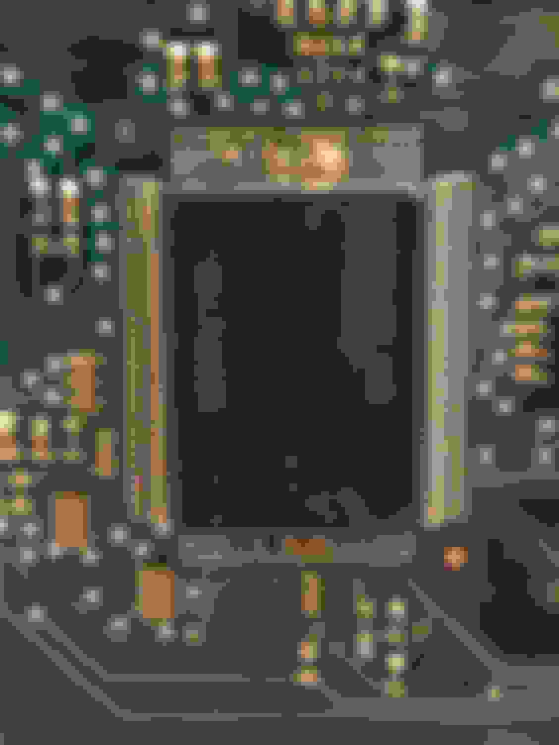
The A/C control arrived today. Having the weekend to myself (meaning an utter lack of HoneyDo�s! 🥳 I tore down the module for an autopsy. NOTE: I used a T7 Torx bit to remove the screws. It was a little tight, so if a T6 exists that�s probably what is needed.
This is a very initial post on what I found so far, a few suspicions as to what�s wrong, and two things I found very unusual.
NEC D78F0948GF microcontroller with corrosion on left side of chip Right side of the chip, more corrosion or just plain dirt (?).
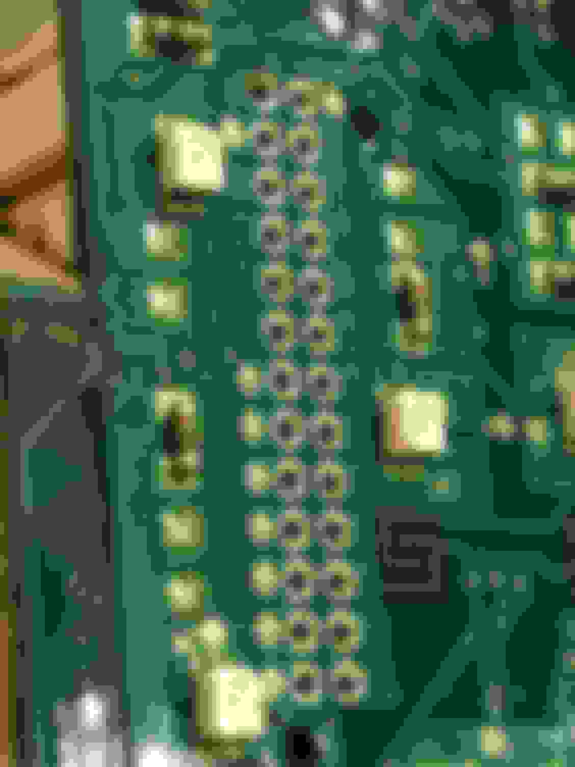
Now this is something I�ve never seen before:
This connector looks like it has been shoved into the board, but never soldered!
This is the back side of the connector the wiring harness is plugged into, notice the lack of any solder!
ssoliman is right. Looks like somebody dumped a cola or something in this thing.
This was odd; I�d have expected two lenses or whatever you want to call them for illuminating both the Warm and Cold sides of the ****. There is a clear plastic light guide for the Cool side that�s missing on the Warm side.
What I think is probably a capacitor, before and after:
Before the scrubbing.
After a scrub with a cut down acid brush and some contact cleaner.
The A/C control arrived today. Having the weekend to myself (meaning an utter lack of HoneyDo�s! 🥳 I tore down the module for an autopsy. NOTE: I used a T7 Torx bit to remove the screws. It was a little tight, so if a T6 exists that�s probably what is needed.
This is a very initial post on what I found so far, a few suspicions as to what�s wrong, and two things I found very unusual.
NEC D78F0948GF microcontroller with corrosion on left side of chip Right side of the chip, more corrosion or just plain dirt (?).
Now this is something I�ve never seen before:
This connector looks like it has been shoved into the board, but never soldered!
This is the back side of the connector the wiring harness is plugged into, notice the lack of any solder!
ssoliman is right. Looks like somebody dumped a cola or something in this thing.
This was odd; I�d have expected two lenses or whatever you want to call them for illuminating both the Warm and Cold sides of the ****. There is a clear plastic light guide for the Cool side that�s missing on the Warm side.
What I think is probably a capacitor, before and after:
Before the scrubbing.
After a scrub with a cut down acid brush and some contact cleaner.


 I tore down the module for an autopsy. NOTE: I used a T7 Torx bit to remove the screws. It was a little tight, so if a T6 exists that�s probably what is needed.