When you click on links to various merchants on this site and make a purchase, this can result in this site earning a commission. Affiliate programs and affiliations include, but are not limited to, the eBay Partner Network.
I used two inch hose and the Sneed bracket (unmodified) on my previous '09 Clubman S. The picture shows the routing, which worked but wasn't great because it rubbed. I put on Gorilla duct tape to help, but it wasn't a good solution.
I removed the backing plates, so I wrapped the ball joints and abs sensors in heat tape...not sure that was necessary, but I didn't want to take any chances.
Last edited by bugeye1031; May 14, 2017 at 03:43 AM.
Reason: added pictures
I haven't looked at the hose routing, but is there a chance that you can flatten the hose? The hoses I've used have a pretty stiff wire in them. I'm thinking that you could use a 2x4 and make the hose oval near the axle?
Anyone have a source for temperature sensitive paint? Would be fun to do some before/after comparisons.
I am actually looking at routing the hose to the caliper bracket show in the first picture in that post you linked to and having the air blow through the gap between the bracket and steering knuckle. I am also thinking of retaining the dust shields in order to trap as much of the ducted-in air as possible to help force it though the rotor vanes.
I use Sneed bracket at the rotor, I did not like the design so I fslipped them and bent thrm around so the air is all going into the center of the rotor instead of the face of the rotor, saw a nice temp drop
I spent last evening trying to route the brake duct hose and didn't like any of the ways to get to the rear of the left side rotor. It doesn't seem like there is enough room and flexibility to handle the suspension movement and steering angles. Very frustrating.
I did look back at the pictures that bugeye posted (bugeye - thanks for the post) and may try again. But one problem I am having is the 2" hose I have does not seem very flexible. I didn't think it would fit between the shock and endlink like he has.
...I removed the backing plates, so I wrapped the ball joints and abs sensors in heat tape...not sure that was necessary, but I didn't want to take any chances.
Actually, wrapping those was a good idea. I melted the cover on one of my abs sensor lines. As for the ball joint, I left a section of the backing plate in placed to keep heat off of it.
I spent last evening trying to route the brake duct hose and didn't like any of the ways to get to the rear of the left side rotor. It doesn't seem like there is enough room and flexibility to handle the suspension movement and steering angles. Very frustrating.
I did look back at the pictures that bugeye posted (bugeye - thanks for the post) and may try again. But one problem I am having is the 2" hose I have does not seem very flexible. I didn't think it would fit between the shock and endlink like he has.
I wonder if the hose could be routed between the axle and the lower A arm.....maybe if it's reshaped from round to a flattened oval? Maybe by routing the hose through an aluminum coupler that has been shaped appropriately.... just a thought....
The SquawSkiBum post at the beginning of this page has a link that shows the hose as you suggested (between the axial and control arm). I did try this as a trial fit, but was concerned about having the hose that close to a rotating part. If that wire inside the hose were to come loose and tangled on the axial, it wouldn't be a pretty picture.
Here is another thought. I have seen some CAIs that route air from that fake hood scoop to the air box. What if that air were, instead, routed to a box on the firewall that then split into two hose connections. The brake duct hoses could then simply follow the steering rack to each side of the car and to each wheel.
Well color me frustrated. Finally got my new rotors, pads, and 2" hose, and some free weekend time. I spent a good chunk of Saturday trying to figure out how to route the hose on the right side. First I discovered that the acetone vapor polishing had caused the adapters to shrink slightly so they didn't fit onto the duct from the bumper. Oh well, I'll just print another set. Then I found that there's not enough room to get the hose routed to behind the hub on the obvious path.
Sunday I tried the other side, same problem. This picture shows the hose not fitting through the gap between the transmission and the front suspension frame.
The good news is the rotor plates in carbon turned out nicely, here's the right side with a new rotor.
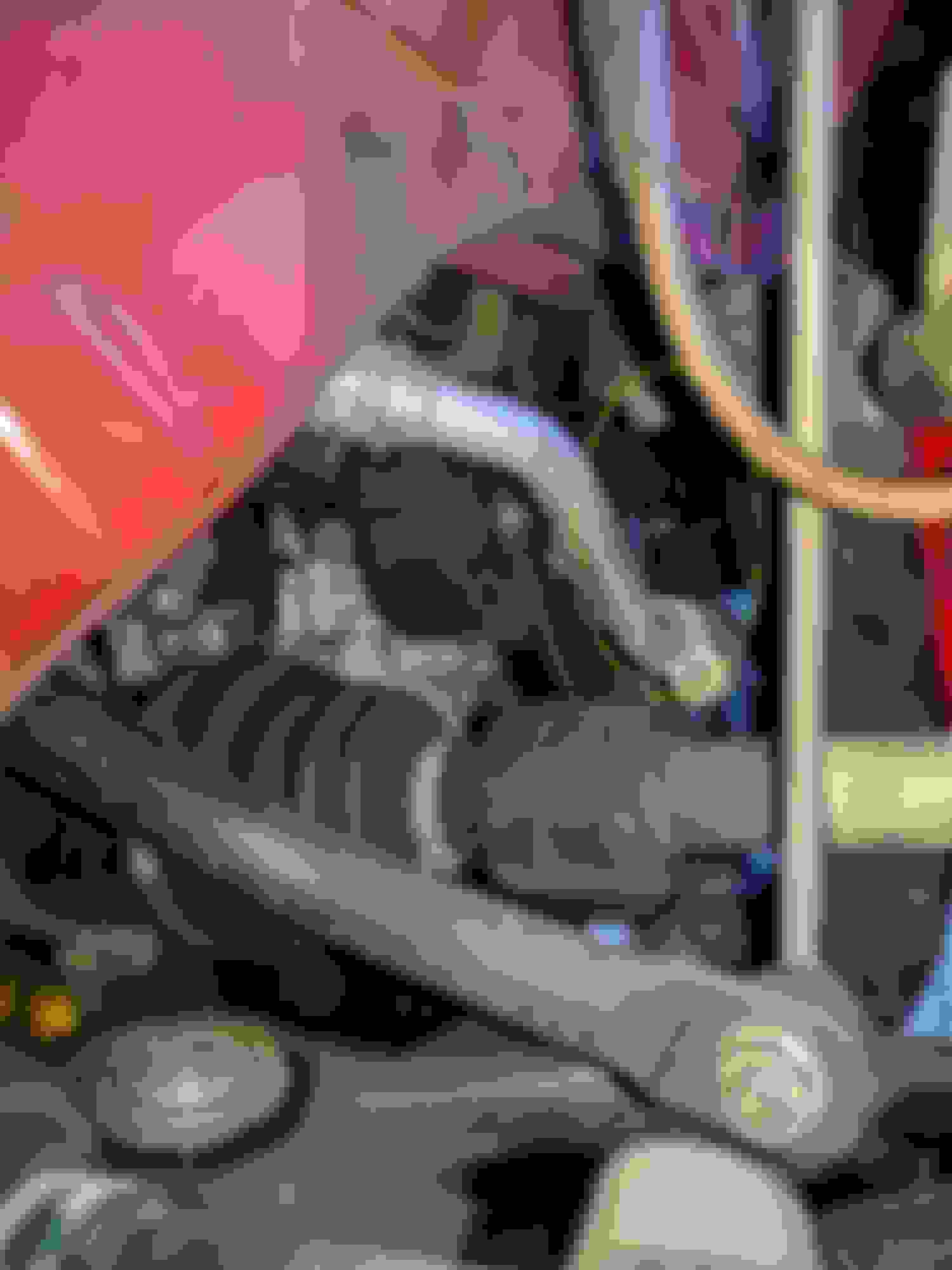
I went back and looked at the pictures I had linked above, the reason I wasn't able to route it that way is because when I installed the Ohlins shocks, I didn't get adjustable swaybar links. Because the stock links are too long for the lowered suspension, the end of the swaybar is pushed down into the space where the hose needs to go to come up behind the hub. The top picture shows the swaybar/endlink in the foreground.
Adjustable swaybar links have been on my to-do list for a while, I guess I finally have to get that done. It still looks like clearance will be tight under the axle.
Update: I ordered adjustable swaybar endlinks from WMW. They showed up and the next Saturday I went out to the garage to fit them. Got the car jacked up, took off the left tire, and compared the length when adjusted as short as it would go to the stock link. Crap, I forgot that I'm lowered with the Ohlins. The stock length is about 295mm, the shortest the adjustable links would go is 280. That's not going to get the job done. So I figured out the thread pitch and ordered a right-hand and left-hand M10-1.25 die, lengthened the threads and cut the link shorter by 40mm.
Today I got them fitted, and looked at running the ducts again. I didn't have time to pull out the fender well liners, but because of the drop with the Ohlins even with the end of the swaybar out of the way there's not enough clearance between the "wishbone" lower suspension arm and the axle. So I either raise the ride height or come up with a creative solution. Current thought is to make another set of custom ducts to get through the tight spots I show in the pictures above. Not sure yet if I will 3D print those or just do a foam mold and layup some carbon over it.
Sigh. One step at a time. At least the new endlinks cured some clunks that had developed in the front end.
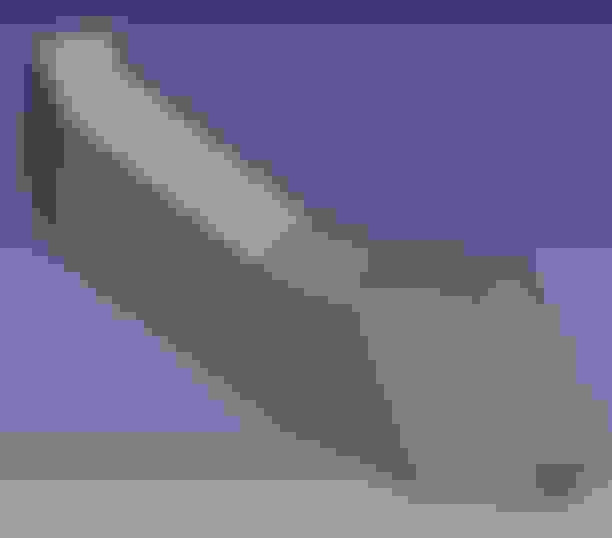
It is going slowly. I have started with some foam shaped to a trapezoidal cros-section - measure, cut, fit, glue, adjust, try again, repeat... then take measurements to transfer into 3D CAD. Then learn new tricks with the CAD program to model it. Looks like this at the moment: (left side, top left of the picture is toward the front of the car.)
This will need to be printed in multiple parts then glued together. After that I think I will cover it with a carbon fiber sleeve to ensure that it doesn't come apart. Of course this needs transitions to circular ends to connect to the flexible duct, the forward one can be integral with the rest of the duct but the rearmost one will have to snap on behind the vertical part of the sub frame. I got real familiar with that part of the car a few weeks ago when replacing the lower control arm and front swaybar bushings.
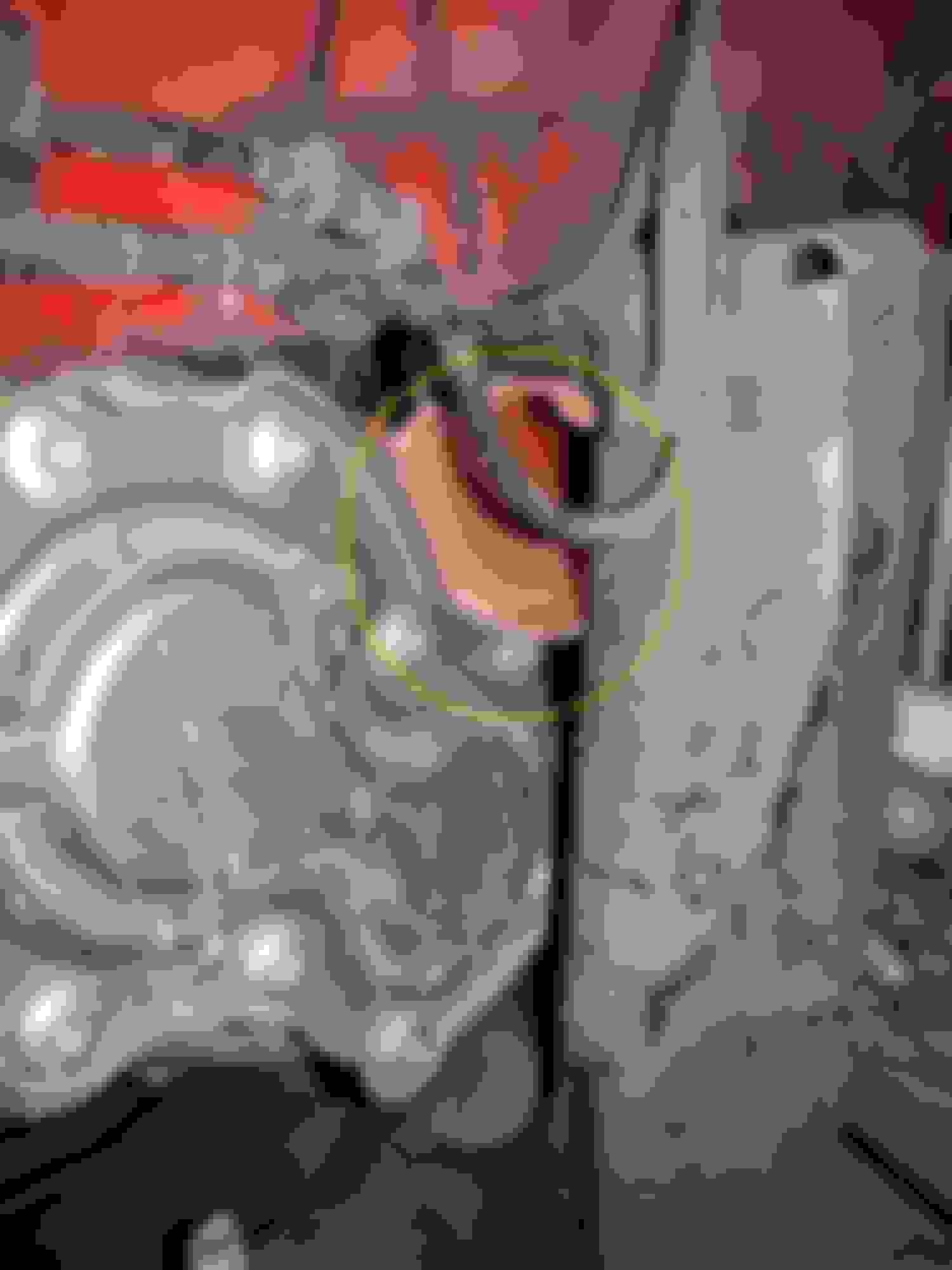
Here is a picture of the space that the duct has to go through. There's about 24mm at the top and 20mm at the bottom. The 2007 - 2010 R56 must have a lot more room in that area than the 2011 - 2013 R56LCI, I have seen pictures of various brake duct solutions on the R56 and they all show flexible duct running through where there just isn't any room on my car, and even if I did cram it through there it would quickly chafe through.
Unfortunately work hasn't left me with much spare time to work on this. If anyone out there knows 3D CAD and wants to help out, PM me.
It is going slowly. I have started with some foam shaped to a trapezoidal cros-section - measure, cut, fit, glue, adjust, try again, repeat... then take measurements to transfer into 3D CAD. Then learn new tricks with the CAD program to model it. Looks like this at the moment: (left side, top left of the picture is toward the front of the car.)
This will need to be printed in multiple parts then glued together. After that I think I will cover it with a carbon fiber sleeve to ensure that it doesn't come apart. Of course this needs transitions to circular ends to connect to the flexible duct, the forward one can be integral with the rest of the duct but the rearmost one will have to snap on behind the vertical part of the sub frame. I got real familiar with that part of the car a few weeks ago when replacing the lower control arm and front swaybar bushings.
Here is a picture of the space that the duct has to go through. There's about 24mm at the top and 20mm at the bottom. The 2007 - 2010 R56 must have a lot more room in that area than the 2011 - 2013 R56LCI, I have seen pictures of various brake duct solutions on the R56 and they all show flexible duct running through where there just isn't any room on my car, and even if I did cram it through there it would quickly chafe through.
Unfortunately work hasn't left me with much spare time to work on this. If anyone out there knows 3D CAD and wants to help out, PM me.
Now I'm going to look at my car, I'm curious if I have as little room as you do. Wish I knew CAD to either help out or design somthing. But once your get it figured out and done you will have a awsome setup.
A bit of progress - finally I have a prototype built to test fit. I had a really hard time figuring out how to model the part on the left where it first turns upwards, then has to turn to the side along an angled line. It isn't just simple miter cuts. Once I had the "ah-ha!" moment with the CAD tool it was really simple. I printed this in 3 pieces - long straight part in the middle, plus the two more complex parts at either end. Acetone melts ABS plastic so I used that to solvent weld the three pieces together. Here it is assembled and sanded. I will have to create another transition back to a round tube that will snap on to the left end, after sliding this through the narrow spot between the frame and transmission (see picture above.) Assuming this fits properly, the plan is to put a carbon fiber braided tube over it. Not strictly necessary but it will make it incredibly strong.
Once I'm happy with the design on the left side, I can create the mirror image part for the right hand side with just a couple of mouse clicks.
Do I assume correctly that this is being sized for 2” hose? In trying to route 2” hose to my wheels, the hose I got (orange silicone) was quite stiff and when the wheel turned and went up and down it would pull hard on the hose. I thought that, if I could have the hose follow the CV shaft, at least one axis of motion would be eliminated or greatly reduced. Do you think you could have your fancy tube come back and down over the drive shaft and exit through an elbow that points to the wheel?
Yes all the parts so far are designed for 2" hose, sounds like I have the same orange silicone hose as you. My thought at the moment is to just transition back to round once through the tight spot (see pic above) and let the hose take care of the bends. Interesting idea though to put an elbow on it. Since tommorow is a holiday, I intend to spend it fiddling with the car to do a test fit and figure out the next piece.
Back to the drawing board - or CAD tool, the test fit was a fail. I thought I had everything measured carefully but it was too fat and didn't fit. Oh well, I have some new ideas, I'm going to start from the back and work forward this time. At least I have the CAD tool learning behind me so it should be faster to design the next iteration.