When you click on links to various merchants on this site and make a purchase, this can result in this site earning a commission. Affiliate programs and affiliations include, but are not limited to, the eBay Partner Network.
Is your plan to size this narrow section with the same or close to the same cross-sectional area as the 2� round?
That was the plan, and also how I ended up with a first attempt that doesn't fit. That narrow area will be a restriction, presently the cross section area is about 1400mm^2 compared to the inside of the round part being about 1800. At the moment I don't see a way around that.
I designed a new part last night that goes from the back end through the constricted area, as shown in the last picture above. I printed it today and will try it out.
You guys are probably getting tired of pictures of my wheel wells. Here's my latest design, this goes through the narrow spot between the transmission and the front subframe. I printed it in two sections and solvent glued them together with acetone.
Seems to fit well:
test with flexible 2 inch duct, wheel mounted and car off the jack, wheel is turned all the way to the right.
It looks like I have a solution for getting through the space between the subframe and transmission. I want to work on the design a bit to smooth out the transition from the narrow duct to round, I don't like the sharp angle. But overall it looks like it will fit! There's more room that it appears in the picture, the depth of field is pretty compressed so stuff looks closer together than it really is. Now I need to work out the connecting piece at the front that will go past the transmission and turn in, this will have to snap on over the piece shown here. I might use the subframe mounting bolts as a way to hold a mounting bracket.
Last edited by squawSkiBum; 06-03-2018 at 09:36 PM.
have you done any flow testing routing to the back of the hub like that?
I was cracking rotors at the track, typically 4 days on a set then the cracks would connect and get to the outside edge. I purchased an airflow meter and did some testing, every extra inch of tube cut flow a little, and every bend cut flow a LOT there was almost no flow at the back of the hub. I switched and run a very short duct on a big bumper inlet, dumping the air pointing at the front calipers instead. So far it's much better, first weekend done with a tiny bit of crazing.
You guys are probably getting tired of pictures of my wheel wells.
Nope, never get tired of seeing this sort of thing.
About cracking rotors. As the temp paint shows, these rotors get very hot (no kidding ). I found that cracking can be reduced by cooling both rotor faces at the same rate. I took the dust shields off my brakes thinking that this would make for better cooling with the air blowing in from the MIN brake ducts. What it did was make for uneven cooling from the inside to the outside of the rotor and the outside rotor face cracked really quickly. What was happening was that air from the brake duct was blowing directly on the inside rotor face, but there was no cooling on the outside face.
I put the dust shields back on. This helped with the cracking but brake temps went back up. To help with the heat I added F1 style brake ducts to the shields which channels that air blast from the MINI brake ducts into the ID part of the rotor at the base of vanes, while still protecting the rotor face. Seems to work pretty well with air blowing through the vanes. I got a number of hard days out of my rotors after making these changes.
As for drilled rotors, I met a guy at WGI who owns a 956 Porsche race car and had it out on the track. Guess what it uses for rotors? Yup, drilled rotors. I asked him about cracking because of the holes. His comment was that �rotors crack�. He said that he has tried other variations but found nothing worked as well as the drilled rotors. I might have to give them a try.
Nope, never get tired of seeing this sort of thing.
To help with the heat I added F1 style brake ducts to the shields which channels that air blast from the MINI brake ducts into the ID part of the rotor at the base of vanes, while still protecting the rotor face. Seems to work pretty well with air blowing through the vanes.
Do you have any pictures of the ducts that you added to the shields?
Agree with not getting tired of pictures and discussion.
I agree with the concerns about cooling the rotor faces evenly, that's why I did the fancy rotor plate in carbon to route the air to the center so it exits through the vanes inbetween the faces. (see last picture in post #41.) A test I did using the shop vac to blow air through the plate into the rotor showed it worked really well to push the air through.
Mr. Blah, what did you use for a flow meter? I have the same worry about the effect of the constrictions and changes of direction, and am working to smooth out the path. I'm thinking about how to measure the flow to test if changes make a difference.
one of those cheap airflow meters I got it off amazon, and a shop vac on blow..
it's crude but effective, the flow drop is really really bad as you go longer or add bends, there are nascar duct formulas on the web too I found one in a couple min, it's almost like inverse square law with light
Do you have any pictures of the ducts that you added to the shields?
Agree with not getting tired of pictures and discussion.
I am not sure if I have any good pictures as I tend to build and install, and right now they are on the car. There are people who more readily snap pictures than I do...
Do you have any pictures of the ducts that you added to the shields?
Agree with not getting tired of pictures and discussion.
I found some pictures and made a composite.
The 2 scopes shown are at the top of the shield. The scoop-looking one (shown on the left side of the picture) faces against the rotation of the wheel to catch the air that is spinning with wheel. The other scoop faces forward to catch the blast of air coming out of the MINI brake duct. For both, the openings are to direct the air into the vane area of the rotor (shown on the left side of the picture).
There is a 3rd deflector (scoop; sorry no pic at this point) that I have mounted to the bolts that hold the brake caliper. This one is just flat, with small sides, and is tilted slightly towards the front of the car. This one, again, catches the blast of air coming out of the MINI brake duct and directs it into the vane area of the rotor.
I was originally very interested in the Sneed Speed kit, but decided why buy when I could build. Then I discovered that there's no way to get any sort of round ducting of meaningful diameter past the vertical arm of the subframe, that's what started me down the path of designing the ducts to get through that narrow spot. (See post 41.)
Interesting to see the different solutions that people have developed.
Last edited by squawSkiBum; 07-08-2018 at 10:07 PM.
Here are some screen grabs of my updated design. The first one is a revised version of the duct to get through the narrow spot between the transmission and the vertical part of the subframe, I figured out how to model a smoother transition and bend to hopefully improve the flow. Otherwise it is very similar to the one in the pictures in post 53.
Here is the other part of the pair. This connects to the one above and extends forward past the transmission before transitioning back to a round cross section so it can connect to the hose coming from the front bumper.
The complete kit on each side will consist of the adapter from the duct in the front bumper (see post 20), a short section of round hose to connect to the pair of ducts pictured above, then another section of hose to connect to the plate that directs the air into the center of the rotor (also in post 20).
I started printing these last week, anticipating some time this weekend to check the fit. Unfortunately half way through the first print the 3D printer fried a connector on the controller board so I need to fix it (again). This project has been a real challenge.
Last edited by squawSkiBum; 07-08-2018 at 10:11 PM.
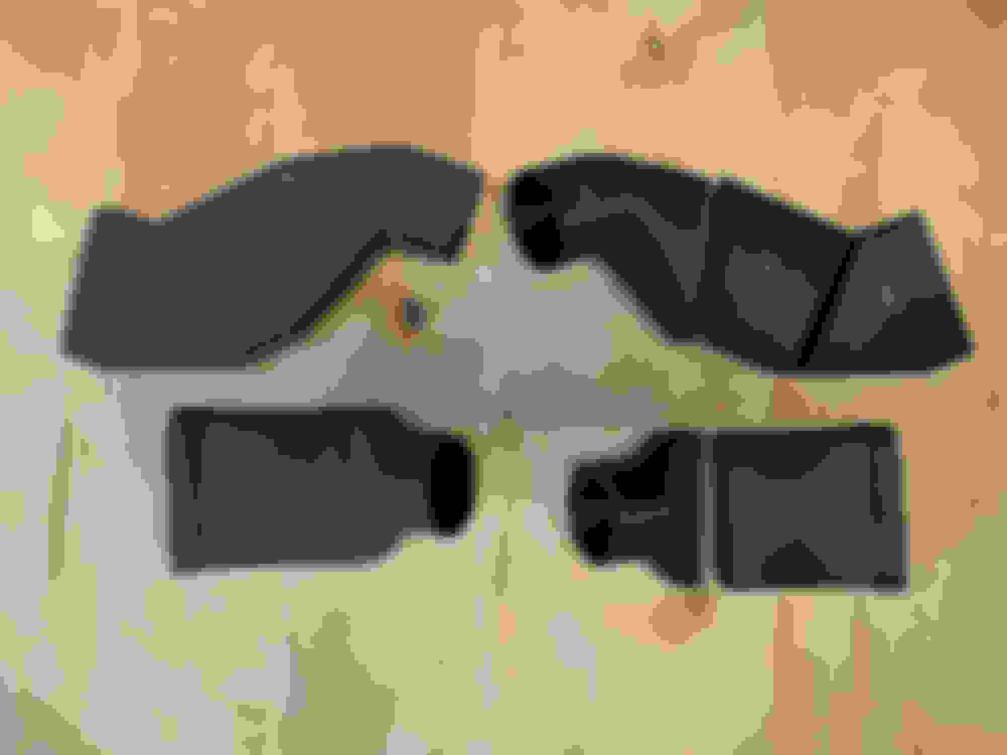
Fixed the 3D printer and printed a whole bunch of parts. Here is the test fit of the piece that gets past the transmission:
Because of the limitations of the 3D printer, I have to print each part in sections. On the left are the 2 duct pieces for the left side, after gluing the pieces together and sanding so they are ready for covering with carbon fiber sleeve. On the right are the individual sections for the right side. These are printed in ABS which is soluble in acetone, so I brush the ends of each piece with acetone and then hold them together until the joint hardens. Then I brush the inside and outside with acetone which smooths the layers and also adds strength since it fuses everything together. After the ABS has hardened, I sand with 100grit so the resin will bond well.
The next step was to brush each piece with resin, slide it inside the carbon fiber sleeve, brush the outside with more resin, and smooth the carbon fiber over the surface. Once everything was tight and the carbon fiber was following the surfaces, I slid it inside some special heat shrink tubing and used the heatgun to shrink it down over the surface. This worked reasonably well, but not perfectly as the shrink tubing doesn't follow the inside curves well. Vacuum bagging would have worked much better for this part but I wasn't about to make the investment in the vacuum pump, bags, peel ply, etc. etc. Maybe in the future...
After the resin cured, I peeled off the shrink tubing, sanded, and then put on a finish coat of resin. Not sure if I will leave this shiny or sand it with 400 - 800 -1200 for a matte finish. Anyway here's the end result. Not cosmetically perfect, but not bad, not that it matters as it won't be seen.
I have one more piece to print which is a little bracket that will fasten to the tops of the bolts that hold the front lower bumper frame. You can see those right under the duct in the first picture of the previous post. The bracket will hold the section that goes past the transmission, and I'll use a long cable tie to secure the other piece to the upright part of the subframe. Almost ready to put the whole system together and try it out! I am assuming that the right hand side is a mirror image of the left, I think that will work but I may be in for a surprise.
Last edited by squawSkiBum; 09-18-2018 at 08:03 PM.
I use Sneed bracket at the rotor, I did not like the design so I fslipped them and bent thrm around so the air is all going into the center of the rotor instead of the face of the rotor, saw a nice temp drop
Do you have any pictures of this? I have the Sneed brackets as well....
With the smoke from the wildfire up north blowing into the area, air quality has been horrible and all the health experts are saying "stay indoors!" The garage is indoors, right? So I spent the weekend in the garage and finally got the last piece done and put the whole thing together.
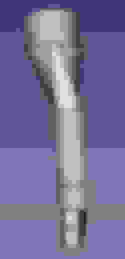
The missing piece was a bracket to hold the ducting (see post #70) in place. I 3D printed some forms, wet out a few layers of carbon and clamped it between the forms, after it cured trimmed and sanded, then expoxied to one part of the duct. (Apologies for the out of focus pic.)
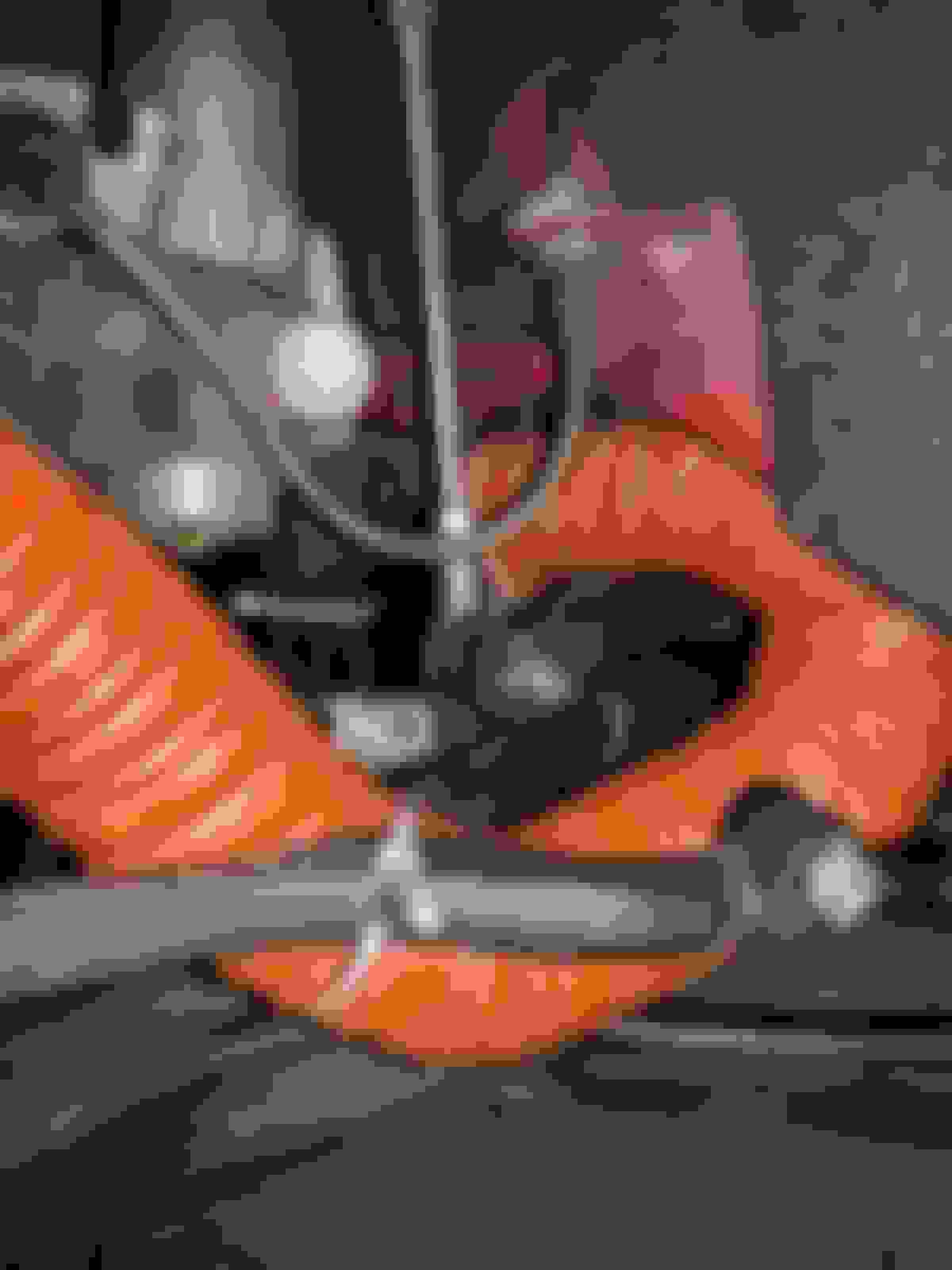
A couple of zip ties and hose clamps later, and it is complete. From front to back, there's the adapters that snap onto the inlets in the front bumper, about 6" of hose, the carbon ducts to get through the narrow spot between the subframe and transmission, then about 18" of hose to the plate at the rotor.
Zip ties hold the bracket onto the subframe bolts, and the other half of the duct is zip tied to the vertical arm of the subframe. Then the hose to the plate at the rotor is zip tied to the steering arm.
I went for a quick test drive to check for problems - looks like there's a bit of chafing on the hose where it passes under the frame before being tied to the steering arm, I already have an idea for a bracket to hold it lower. I'll check after a few weeks for signs of wear on all the other pieces.
I only installed the ducting on the left side, right side is still stock so I can compare rotor temp left vs. right. Stay tuned to see if this actually works...
Wow! Nice work.
But, Crap, that is tight in there. I am not surprised about the chaffing at the frame area With the brake line and end link in there and other things, there is just no room for anything else.
Thanks. Yes, it is TIGHT, hard to find room to get my hands in there with a tool to tighten the hose clamp.
We have been getting some much needed rain the last few days, but this afternoon it cleared up and dried out for a while so I went out and did several hard 60 -> 20 slow downs to get the rotors warmed up, then drove about 1/2 mile before coasting to a stop. (I happen to live close to a stretch of road where it is possible to do that safely.) I tried to get accurate temps using an IR thermometer that goes to over 700F that we have in the lab at work. It's impossible to get an accurate IR temperature reading off of the rotor where the pads contact it because it is too shiny and the emissivity is low, so I was trying to target the inner part of the rotor between the face and the hub where it is painted black. The highest temperature I could get was 285F, the left side with my new ducting was at best about the same as the un-modified right side, at worst maybe 10 degrees hotter. There's a lot of variation in the measurement depending on exactly where I aimed the IR detector, but I definitely didn't get the "hey look it works!" result I was hoping for. I should probably get a contact measurement probe.
Maybe Mr. Blah was right, with all the twists and turns there's too much loss of airflow. I'm not ready to give up yet, I need to order some temperature sensitive paint and work on refining the measurements. Also thinking about how to set up a way to measure the pressure drop through the ducting - basically I need to set up a flow bench and then figure out if there's some high resistance part of the path that I can improve.
 05-30-2018, 05:42 PM


 ). I found that cracking can be reduced by cooling both rotor faces at the same rate. I took the dust shields off my brakes thinking that this would make for better cooling with the air blowing in from the MIN brake ducts. What it did was make for uneven cooling from the inside to the outside of the rotor and the outside rotor face cracked really quickly. What was happening was that air from the brake duct was blowing directly on the inside rotor face, but there was no cooling on the outside face.