
Interior/Exterior LED Stock Radio Mod *NOT COMPLETE*


Thread Starter
|
2nd Gear
Joined: Aug 2009
Posts: 87
Likes: 0
From: A
LED Stock Radio Mod *COMPLETED!*
To be clear, And Niceties aside, don't do this if your not sure of yourself.
If you have seen the led gauge mod thread, this is similar. This is more of a how to though, since i don't like exclusivity....
Requirements:
Small Phillips head, pointy tip, not blunt.
Small Flat head for gentle prying
Soldering Iron
Solder
Solder Wick if you have it, if not... Creativity...
43(add 5 or 8 for mistakes) 0603 SMD LED
○Stock color is orange which is low voltage.
○you should be good with any color since other colors except
○amber/yellow draw more power than orange.*
Beer/beverage
Wet paper towel or sponge for soldering iron cleaning.
Needle nose pliers
White Computer paper
Scissors, Razor blade
very fine needle point tweezers
Step One:
Remove radio from vehicle. I'm not going to go into how to remove it. there's tons of threads
on this. if you cant remove your radio, close this thread.
Step Two:
Find a place clear of debris and plenty of light so you can see screws and parts. Get a piece of paper
and draw circles on it and name them so you remember where the screws went in the radio. Very
helpful since some of the screws are different sizes where you think they would be the same.
Step Three:
Prepare to dig in.
You'll need to remove some screws... Get out your paper.
Remove Side screws.
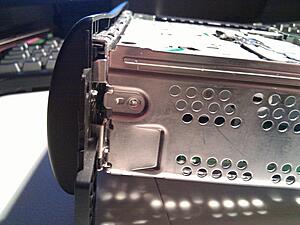
http://imgur.com/o15B1.jpg
Remove Back screws.
http://imgur.com/Des0Q.jpg
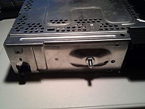
Remove Bottom Screws.
http://imgur.com/VVLSw.jpg
Remove Top via metal clips on the side that need to be moved slightly with that handy flat head.
Remove screws that sit deep inside those two round holes in the CD Carriage. These hold
the faceplate on. DON'T MISS THESE or you'll rip the front off in frustration.
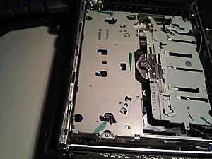
http://imgur.com/23dV4.jpg
Some screws can stay in, but nothing moves if you take em all out. Remember where these screws
go. Do not CROSS Thread when you put them back in. If they don't fit, Don't Force.
Put the Cd Carriage/Back half or radio out of way, some place safe. We wont need it until reassembly.
Grab the Faceplate. you'll need to remove the metal mount. Look for two small green locktite
covered screws. These are different lengths. Long on the right, short on the left. By the way,
i know the metal in my picture is bent. i smashed my radio accidentally with a sub woofer. meh.
http://imgur.com/2EhrA.jpg
you'll need to remove your volume/power ****. Pull on that sucker like your life depends on it.
Very tuff to get off. Remove signal wires, remove retaining screw.
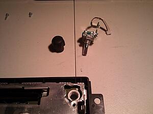
http://imgur.com/IHzdd.jpg
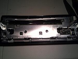
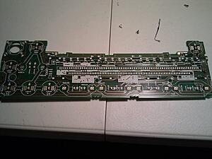
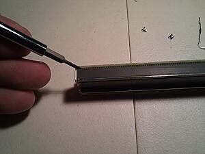
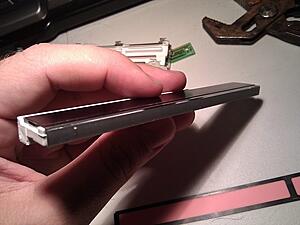
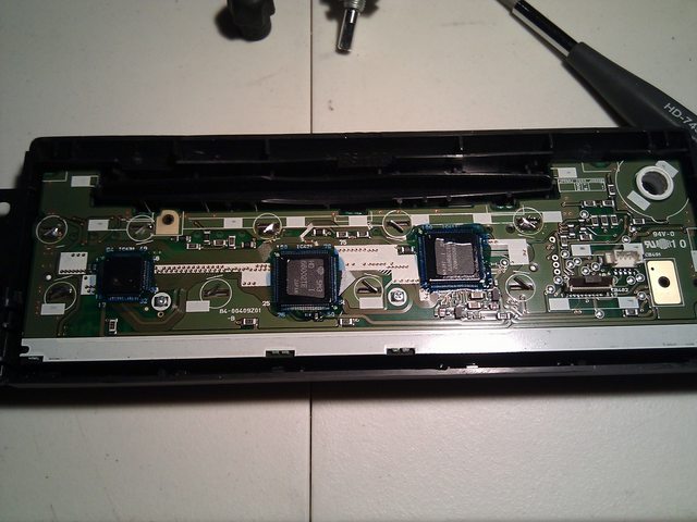
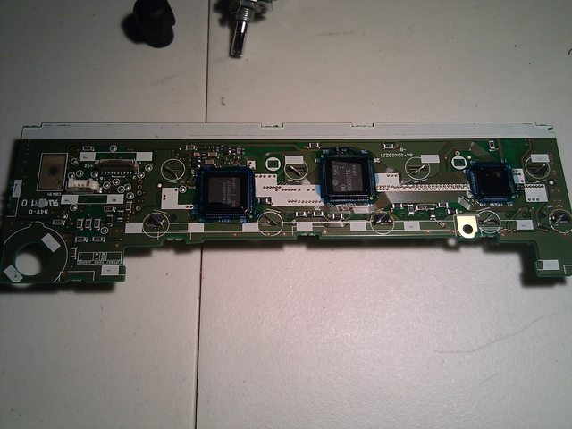
Remove the two screws on the Circuit board. Remember these screws.
You should now be able to pop off the face plate.
http://imgur.com/YYKBH.jpg
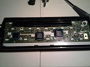
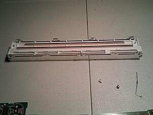
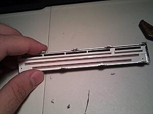
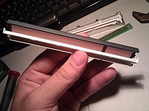
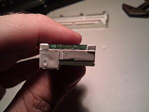
You should now have the below. Bust out your soldering iron, wire wick, and pliers. If you have
no wire wick, you'll have to heat the solder on the retention clips, and tap the unit on the table
to remove the solder. (Maybe i should go buy wire wick... lol) Use the soldering iron to push
the soldered clips back into a straight line, and the pliers to move the unsoldered ones.
Don't stab yourself, or burn yourself. you should now have something like this:
http://imgur.com/Y60wS.jpg
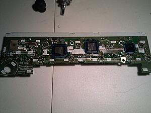
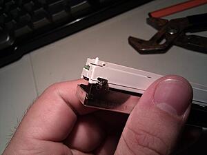
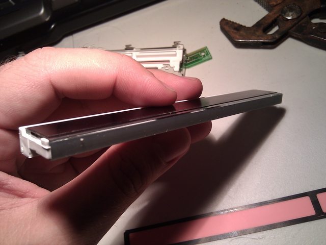
Next step is to remove the LCD to change the orange light filter.
Push the retaining clips through the board with that small flat head. keep your soldering
Iron handy, since you may not have gotten enough solder off to fit through the hole.
DO NOT BEND the circuit board. if you hear cracking, that sounds like sharp pops, you might
as well call it quits; you have a 50/50 chance of the radio working afterward.
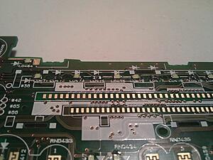
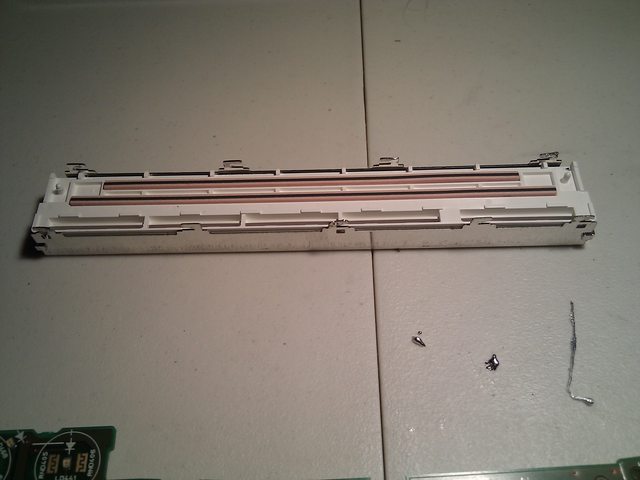
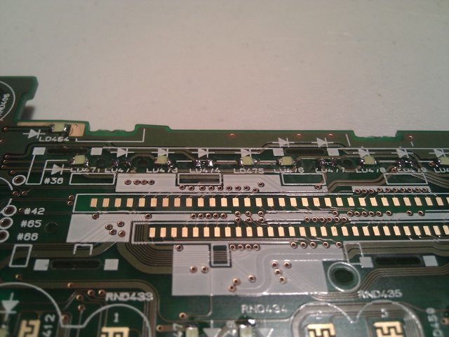
Once you manage to get the LCD disconnected, you should be able to count all the LED's
that you will need. the number you need is at the top, i counted for you.
http://imgur.com/iXy7d.jpg
Beer Break....

http://imgur.com/JdCnS.jpg
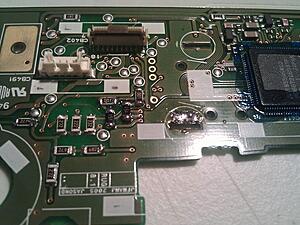
You finished your beer... depending on ABV%, you may be trashed, and You have the LCD off... Now what!?
http://imgur.com/FmMqa.jpg
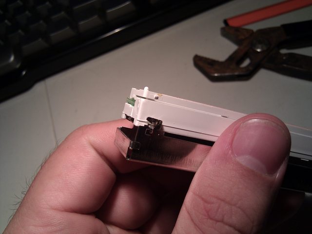
you gotta disassemble that sucker to replace the filter. if you don't, any color you put in will remain orange.
You'll need to put your index finger on the front of the LCD, and grasp the shiny metal between
your thumb and middle finger. Apply pressure to the LCD(not too much!) and separate the clips
you un-soldered from the white plastic with your fingernail or a screwdriver. you should see the
plastic raise a bit. this means its coming out! keep working around it to get it out.
http://imgur.com/gdP5V.jpg
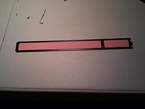
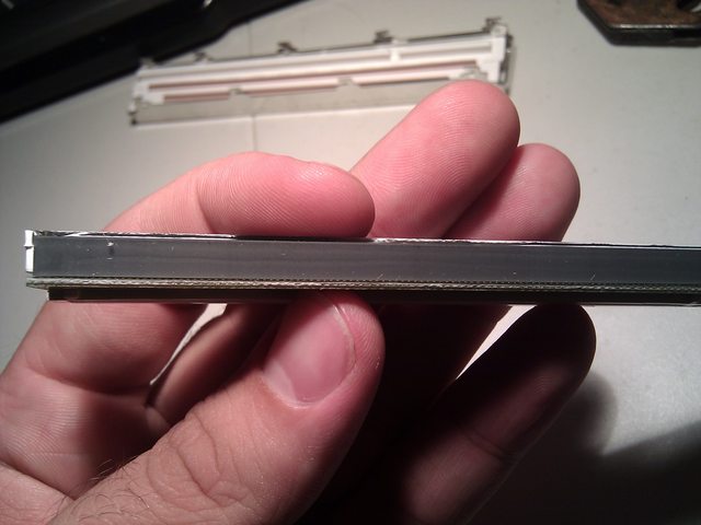
From this point forward, be VERY CAREFUL. i cant stress this enough. On the LCD there is a gray
Zebra conductor band. This is applied with heat, and if you remove it, your LCD may not display
correctly again. Take every precaution to not crack it off. The pink bands are OK to remove since
they are connected by the pressure of the board in the LCD.
Gray Band:

http://imgur.com/cVf8m.jpg
Pink Bands:
http://imgur.com/P9U4K.jpg
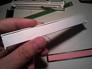
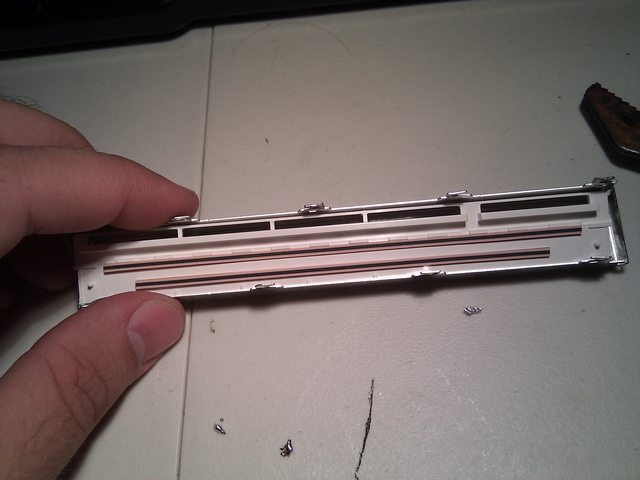
To Disassemble the LCD:
Remove the tray that the pink bands sit in at the very top of the picture.
It may be a bit hard to remove, since some of it is down in the LCD portion.
work at it till you see Circuit board. Set the pink bands and tray aside.
http://imgur.com/gdP5V.jpg
Remove the Circuit board. Work carefully to remove this since the side you need to separate is
connected to the gray band. Separate the gray band from the PCB, *NOT* the glass. Once separated,
tilt back the PCB away from the gray band, and it should come right off. Put the PCB Aside.
http://imgur.com/i0ZSo.jpg
Remove the LCD.
Be VERY Careful. If you were not careful thought this, now is the time. you'll have to remove
the LCD from the white plastic light tray without breaking it, or separating the gray band.
Its not terribly difficult, but can be a bit scary.
Success!
http://imgur.com/HkZZd.jpg
Peel off the orange filter from the LCD. mine was kinda glued/melted on.
http://imgur.com/swJ0Y.jpg
Use the orange filter as a template. I had to cut out the black border on the filter also.
it needs to be there for the extra thickness to push down the LCD contacts.
Cut around it on top of a piece of white printer paper.
i used a snap-off box cutter. Their like 25 cents at the dollar store. go get one lazy.
Fit white paper cutout in place of the orange filter. Put into light tray to ensure nice fit:
http://imgur.com/x510N.jpg
Put unbroken LCD back into light tray:
http://imgur.com/Bnnwt.jpg
Fit PCB back on, it only goes one way, and tilts back in.
http://imgur.com/dn7TL.jpg
MAKE SURE EVERYTHING IS ALIGNED AND STRAIGHT!
Pop Pink band tray back on and sit into metal retainer:
http://imgur.com/FmMqa.jpg
Work back into metal tray slowly, and your end result should be:
http://imgur.com/FmMqa.jpg
By now, your LED's should have came. Mine did not. Still have to order them... all 43 + 8 extra.
Since i have to wait for my LED's, you gotta wait for the how/to finish. Sorry, that's
the way it is. Im sure most of you wont mind though since this is a little dicey, and most
are not brave enough to tackle this challenge. haha. :p
Anyway, let me know what you think, and what i could improve in this Article. my writing
skills aren't exactly collegiate, but they are doctorate.... and i mean the kind that writes
prescriptions.. as in skewed. unreadable. *sigh*
○
○
○
○
○
○
○
Finished.
Solder your LED's back on in the correct polarity. marking on the LED facing the point of the triangle on the board.
Like this:
these are the resistors i was shorting to get a brighter output and use more LEDs.
Don't do this. Its pointless.
Remember how you got it all apart? no? excellent. now put it all back together.
This, Is the final product of my toils:
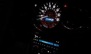
And my whole dash:
If you have seen the led gauge mod thread, this is similar. This is more of a how to though, since i don't like exclusivity....
Requirements:
Small Phillips head, pointy tip, not blunt.
Small Flat head for gentle prying
Soldering Iron
Solder
Solder Wick if you have it, if not... Creativity...
43(add 5 or 8 for mistakes) 0603 SMD LED
○Stock color is orange which is low voltage.
○you should be good with any color since other colors except
○amber/yellow draw more power than orange.*
Beer/beverage
Wet paper towel or sponge for soldering iron cleaning.
Needle nose pliers
White Computer paper
Scissors, Razor blade
very fine needle point tweezers
Step One:
Remove radio from vehicle. I'm not going to go into how to remove it. there's tons of threads
on this. if you cant remove your radio, close this thread.
Step Two:
Find a place clear of debris and plenty of light so you can see screws and parts. Get a piece of paper
and draw circles on it and name them so you remember where the screws went in the radio. Very
helpful since some of the screws are different sizes where you think they would be the same.
Step Three:
Prepare to dig in.
You'll need to remove some screws... Get out your paper.
Remove Side screws.

http://imgur.com/o15B1.jpg
Remove Back screws.

http://imgur.com/Des0Q.jpg
Remove Bottom Screws.

http://imgur.com/VVLSw.jpg
Remove Top via metal clips on the side that need to be moved slightly with that handy flat head.
Remove screws that sit deep inside those two round holes in the CD Carriage. These hold
the faceplate on. DON'T MISS THESE or you'll rip the front off in frustration.

http://imgur.com/23dV4.jpg
Some screws can stay in, but nothing moves if you take em all out. Remember where these screws
go. Do not CROSS Thread when you put them back in. If they don't fit, Don't Force.
Put the Cd Carriage/Back half or radio out of way, some place safe. We wont need it until reassembly.
Grab the Faceplate. you'll need to remove the metal mount. Look for two small green locktite
covered screws. These are different lengths. Long on the right, short on the left. By the way,
i know the metal in my picture is bent. i smashed my radio accidentally with a sub woofer. meh.

http://imgur.com/2EhrA.jpg
you'll need to remove your volume/power ****. Pull on that sucker like your life depends on it.
Very tuff to get off. Remove signal wires, remove retaining screw.

http://imgur.com/IHzdd.jpg
Remove the two screws on the Circuit board. Remember these screws.
You should now be able to pop off the face plate.
http://imgur.com/YYKBH.jpg
You should now have the below. Bust out your soldering iron, wire wick, and pliers. If you have
no wire wick, you'll have to heat the solder on the retention clips, and tap the unit on the table
to remove the solder. (Maybe i should go buy wire wick... lol) Use the soldering iron to push
the soldered clips back into a straight line, and the pliers to move the unsoldered ones.
Don't stab yourself, or burn yourself. you should now have something like this:
http://imgur.com/Y60wS.jpg
Next step is to remove the LCD to change the orange light filter.
Push the retaining clips through the board with that small flat head. keep your soldering
Iron handy, since you may not have gotten enough solder off to fit through the hole.
DO NOT BEND the circuit board. if you hear cracking, that sounds like sharp pops, you might
as well call it quits; you have a 50/50 chance of the radio working afterward.
Once you manage to get the LCD disconnected, you should be able to count all the LED's
that you will need. the number you need is at the top, i counted for you.

http://imgur.com/iXy7d.jpg
Beer Break....

http://imgur.com/JdCnS.jpg
You finished your beer... depending on ABV%, you may be trashed, and You have the LCD off... Now what!?
http://imgur.com/FmMqa.jpg
you gotta disassemble that sucker to replace the filter. if you don't, any color you put in will remain orange.
You'll need to put your index finger on the front of the LCD, and grasp the shiny metal between
your thumb and middle finger. Apply pressure to the LCD(not too much!) and separate the clips
you un-soldered from the white plastic with your fingernail or a screwdriver. you should see the
plastic raise a bit. this means its coming out! keep working around it to get it out.
http://imgur.com/gdP5V.jpg
From this point forward, be VERY CAREFUL. i cant stress this enough. On the LCD there is a gray
Zebra conductor band. This is applied with heat, and if you remove it, your LCD may not display
correctly again. Take every precaution to not crack it off. The pink bands are OK to remove since
they are connected by the pressure of the board in the LCD.
Gray Band:
http://imgur.com/cVf8m.jpg
Pink Bands:
http://imgur.com/P9U4K.jpg
To Disassemble the LCD:
Remove the tray that the pink bands sit in at the very top of the picture.
It may be a bit hard to remove, since some of it is down in the LCD portion.
work at it till you see Circuit board. Set the pink bands and tray aside.
http://imgur.com/gdP5V.jpg
Remove the Circuit board. Work carefully to remove this since the side you need to separate is
connected to the gray band. Separate the gray band from the PCB, *NOT* the glass. Once separated,
tilt back the PCB away from the gray band, and it should come right off. Put the PCB Aside.

http://imgur.com/i0ZSo.jpg
Remove the LCD.
Be VERY Careful. If you were not careful thought this, now is the time. you'll have to remove
the LCD from the white plastic light tray without breaking it, or separating the gray band.
Its not terribly difficult, but can be a bit scary.
Success!

http://imgur.com/HkZZd.jpg
Peel off the orange filter from the LCD. mine was kinda glued/melted on.

http://imgur.com/swJ0Y.jpg
Use the orange filter as a template. I had to cut out the black border on the filter also.
it needs to be there for the extra thickness to push down the LCD contacts.
Cut around it on top of a piece of white printer paper.
i used a snap-off box cutter. Their like 25 cents at the dollar store. go get one lazy.
Fit white paper cutout in place of the orange filter. Put into light tray to ensure nice fit:

http://imgur.com/x510N.jpg
Put unbroken LCD back into light tray:
http://imgur.com/Bnnwt.jpg
Fit PCB back on, it only goes one way, and tilts back in.

http://imgur.com/dn7TL.jpg
MAKE SURE EVERYTHING IS ALIGNED AND STRAIGHT!
Pop Pink band tray back on and sit into metal retainer:
http://imgur.com/FmMqa.jpg
Work back into metal tray slowly, and your end result should be:
http://imgur.com/FmMqa.jpg
By now, your LED's should have came. Mine did not. Still have to order them... all 43 + 8 extra.
Since i have to wait for my LED's, you gotta wait for the how/to finish. Sorry, that's
the way it is. Im sure most of you wont mind though since this is a little dicey, and most
are not brave enough to tackle this challenge. haha. :p
Anyway, let me know what you think, and what i could improve in this Article. my writing
skills aren't exactly collegiate, but they are doctorate.... and i mean the kind that writes
prescriptions.. as in skewed. unreadable. *sigh*
○
○
○
○
○
○
○
Finished.
Solder your LED's back on in the correct polarity. marking on the LED facing the point of the triangle on the board.
Like this:
these are the resistors i was shorting to get a brighter output and use more LEDs.
Don't do this. Its pointless.

Remember how you got it all apart? no? excellent. now put it all back together.
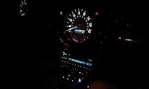
This, Is the final product of my toils:

And my whole dash:

Last edited by wyefye; Sep 10, 2010 at 07:48 PM.

1st Gear
Joined: Aug 2010
Posts: 47
Likes: 0
Dude! I am in the middle of this project as well. I just got the LCD seperated from the main PCB and need to open it up to pull thr orange filter. Thanks for starting a how-to on this, and identifying what LED spec to get.


Dude... Way too involved for my pea-brain. Glad to see that good ol' DIY spirit is thriving. Cant wait to see some pix!
Trending Topics
Thread Starter
|
2nd Gear
Joined: Aug 2009
Posts: 87
Likes: 0
From: A
LED's just came yesterday. have not had time to solder due to girlfriend and other things.... namely my dogs destroying my house.
Maybe the 03's have a different size that the 06's head unit. Could you take a picture of the LED's? maybe they are plcc 2 leds; they are all over the dash in the 06, maybe they carried over to the Head unit in the 03.
PLCC 2 LED:

Maybe the 03's have a different size that the 06's head unit. Could you take a picture of the LED's? maybe they are plcc 2 leds; they are all over the dash in the 06, maybe they carried over to the Head unit in the 03.
PLCC 2 LED:
1st Gear
Joined: Aug 2010
Posts: 47
Likes: 0
My H/U has 0805s. All the illuminations LEDs are nice and bright, but the 21 under the LCD are very dim. Before I unsoldered the orange ones, I verified the locations of them, and the LCD lights were just as bright as the illumination lights.
Thread Starter
|
2nd Gear
Joined: Aug 2009
Posts: 87
Likes: 0
From: A
I'm in process of soldering up.
I should have it completed tonight.
Ill let you know what I come up with.
Already, I can think of a fix, but I need to make sure I don't
overvolt and burn out some leds or the radio.
I should have it completed tonight.
Ill let you know what I come up with.
Already, I can think of a fix, but I need to make sure I don't
overvolt and burn out some leds or the radio.
Thread Starter
|
2nd Gear
Joined: Aug 2009
Posts: 87
Likes: 0
From: A
under the LCD, the LED's are connected in groups of three.
since the amber led's take a little over half of the voltage the white led's take, im going to try skipping the middle LED's in the group of three by bridging the contact pad. that *should* give them almost full voltage. maybe.
this is all theory, since i cant find my volt meter... lol
let me do this first, peep the temp output on the resistors and the LED's and gauge the light output thru the LCD to see if it is worth it.
Thread Starter
|
2nd Gear
Joined: Aug 2009
Posts: 87
Likes: 0
From: A
fun fun. all soldered back together. it may be short for the amendment to my first post, but if you got your radio apart, you can get it all back together.
Enjoy.
Let me know if you need any help!
Enjoy.
Let me know if you need any help!
Last edited by wyefye; Sep 10, 2010 at 07:54 PM. Reason: error prevention.
1st Gear
Joined: Aug 2010
Posts: 47
Likes: 0
under the LCD, the LED's are connected in groups of three.
since the amber led's take a little over half of the voltage the white led's take, im going to try skipping the middle LED's in the group of three by bridging the contact pad. that *should* give them almost full voltage. maybe.
this is all theory, since i cant find my volt meter... lol
let me do this first, peep the temp output on the resistors and the LED's and gauge the light output thru the LCD to see if it is worth it.
since the amber led's take a little over half of the voltage the white led's take, im going to try skipping the middle LED's in the group of three by bridging the contact pad. that *should* give them almost full voltage. maybe.
this is all theory, since i cant find my volt meter... lol
let me do this first, peep the temp output on the resistors and the LED's and gauge the light output thru the LCD to see if it is worth it.


1st Gear
Joined: Sep 2010
Posts: 22
Likes: 0
Wanted to say thanks for the DIY--when the amp in my head unit blew I bought a refurbished one online, but the refurb had a cracked face plate. Used this to swap 'em out!
There's a screw on top of the cd carriage near the black heat sink (?); just try not to strip it out.
There's a screw on top of the cd carriage near the black heat sink (?); just try not to strip it out.
Thread Starter
|
2nd Gear
Joined: Aug 2009
Posts: 87
Likes: 0
From: A
Sorry for not replying directly.
White leds and white printer paper. The lcd is naturally black, so shining a high intensity white led thru it makes it look blue. Also, a white led is really just an over driver blue led.
-wyefye
White leds and white printer paper. The lcd is naturally black, so shining a high intensity white led thru it makes it look blue. Also, a white led is really just an over driver blue led.
-wyefye

Neutral
Joined: Sep 2011
Posts: 5
Likes: 0
Hmm, peculiar. I like the white look however, My car is Royal blue so I chose all blue leds.
Anyhow, I just got my larger LEDs in the mail today.
I started at my steering wheel controls (cruise control buttons which take a different size) and i am moving to the tach and speedo next.
I am recording all my purchases to make yet another How-To Thread.
If anyone has any questions or think they can't do it, feel free to PM me!
Thread Starter
|
2nd Gear
Joined: Aug 2009
Posts: 87
Likes: 0
From: A
It's not really peculiar at all; but expected. watch the size of your LEDs, you may find they don't fit if you chose the wrong ones.
good luck on the how-to, you saw how many steps there were for the radio... that's why i got lazy and didn't post the rest.
-Wyefye
p.s. way to revive a dead thread, hah.
good luck on the how-to, you saw how many steps there were for the radio... that's why i got lazy and didn't post the rest.
-Wyefye
p.s. way to revive a dead thread, hah.
Neutral
Joined: Sep 2011
Posts: 5
Likes: 0
I guess we will see when we get there. Did you ever do the A/C controls? I haven't opened them yet or seen a thread on them.
I used a caliper to measure the size of the factory leds and then spec'd some on ebay. I am recording their sizes for my thread when i am done. It appears so far that the speedo, tach, clock, and lower switch panel all take the same size. Judging from your photos, i think the radio may use the smaller size like the cruise controls?
P.S. i believe the small size is a 1206 smd and the larger is a 1210.