When you click on links to various merchants on this site and make a purchase, this can result in this site earning a commission. Affiliate programs and affiliations include, but are not limited to, the eBay Partner Network.
I am in the process of putting a TPR2 Head on that is a subject of another thread I have posted in the Gen1 Mod Section, here. I already have a water/meth injection system that I put together by using various parts to address the heat I knew I would get from going with at 19% pulley ratio. The thread I did for the pulley and injection is here. Never thought I would be doing more engine mods so along with with going down to a 17% ratio with the TPR2 I also got thinking about a larger intercooler.
There are several threads here about larger intercoolers and one includes testing of various different brands, here. There are also several about the ebay intercoolers out there. If you do any searching on the web about this matter you will see that most agree that the GP1 intercooler installed on that limited edition back in 2006 is about the best relative to recovery time. There are a couple of other units that react well relative to recovery but they are pushing over $500 and the GPs are well over $1,000 if you can even find one. The Ebay intercoolers can be had for around $80 and if you are only doing country driving then they do quite well but when you get them in traffic the recovery has much to be desired. Some of the Ebay units also have issues with proper fit.
I got thinking about all this stuff and from what I could find the only difference between the stock oem and GP intercooler is that the GP has two more rows of tubes along with a larger cover. I am not a machinist but also not afraid to think outside the box and try my hand at doing something different. I figured out that that 2008 and up Chevy Cobalt SS had Brembo calipers that with a little work would fit my MINI. I fabricated some shims with some electrical box covers that you can see in the Brake thread here. So with my Dremel, my drill, a sawzall, my table saw and my time I figured I would see if I could make a GP Intercooler.
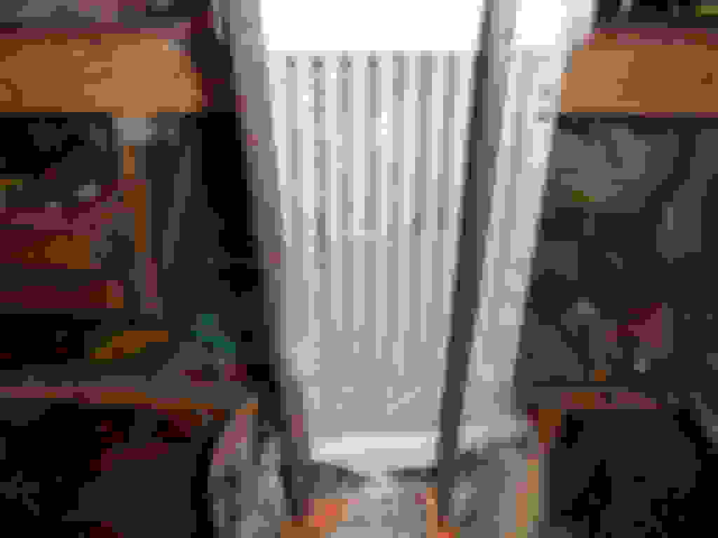
First, here is a picture with the GP1 ic on top and the stock oem on the bottom.
Next I found a guy on Ebay that has allot of used oem intercoolers for $36 shipped so I bought two from him. They came in today and did a leak test by making up a gasket, clamping a plate on the gasket and then filled the ic with water. Wanted to make sure there were now ruptured tubes.
Next , I chose one and started to take it apart. There are removable rubber/plastic clips that the top bolts go through. You remove the clips.
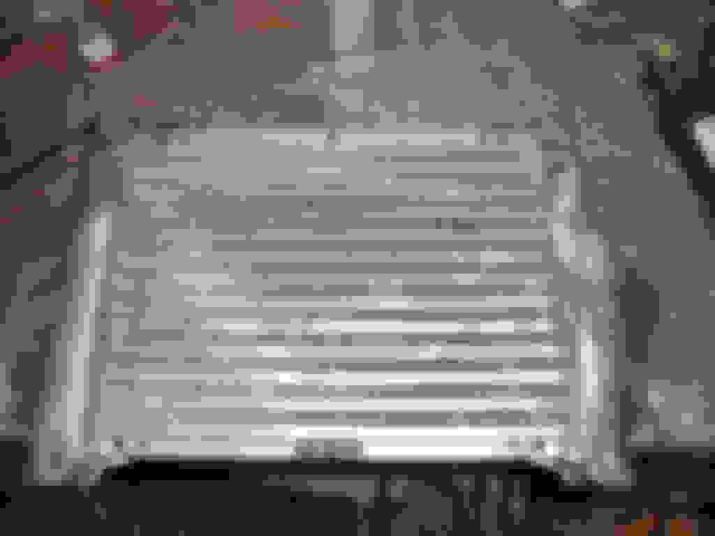
I then drilled and dremeled so that the end of the intercooler would be open. It appears the factory brazed all the pieces together. After I cut the holes in the end I ground the second layer of the frame out so that the air would flow better.
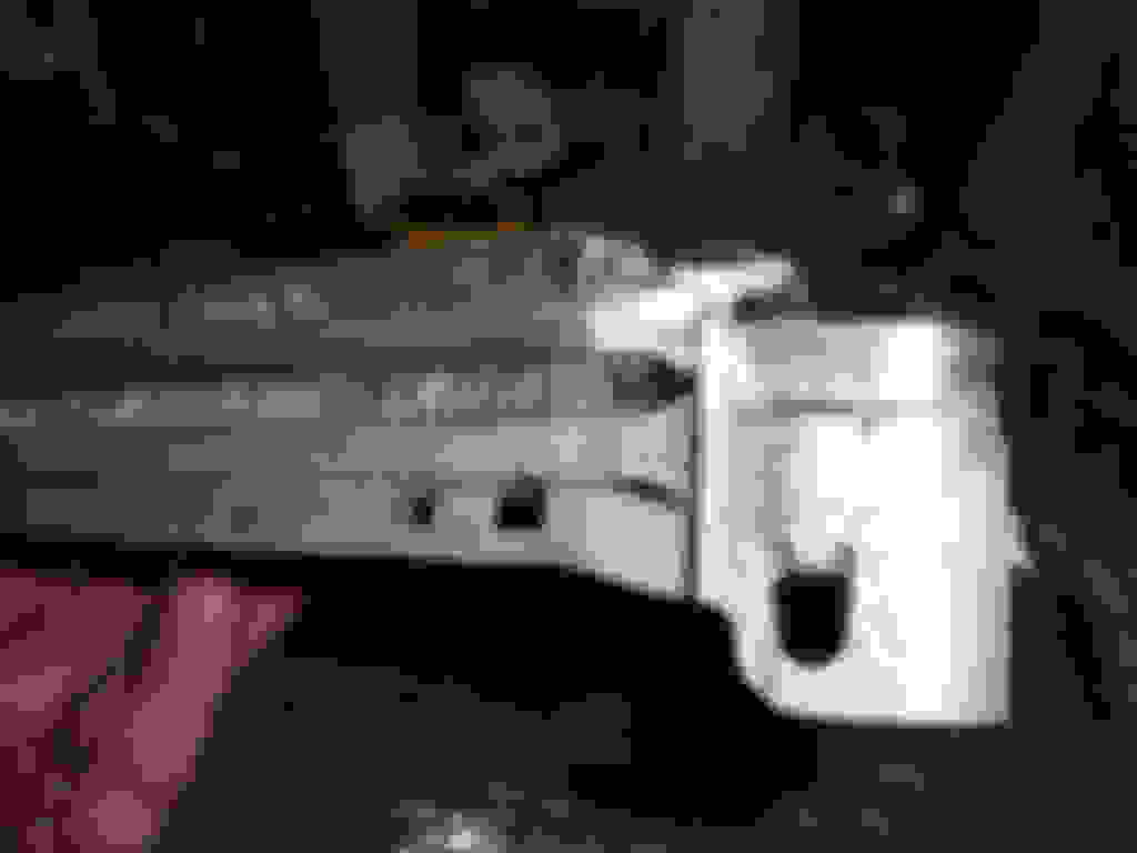
I also cut the frame flanges off. The picture below is the top/motor side of the ic. The bottom unit has the flange and tabs, the top is what I cut.
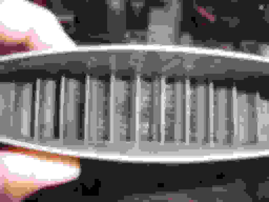
In the next picture you can see the inside of the ic. There are fins inside the tubes similar to what you can see on the outside between the tubes.
I took the second unit I bought and cut it on my table saw. I wanted the two upper tubes to add to the stock unit.
I cut on the edge of a tube so that I had a flat surface that I could mate up with the other unit.
You can see where the fins were inside the tube that I cut.
Then I used my dremel to cut and shape the two tube section so that it would fit with the other unit.
In the last picture you can see where due to the left larger horn there is a gap.
The next step will be to braze pieces in where the old bolt holes were, tab holes, and also infill where the larger horn was. I will braze some straps to make the unit more rigid. I plan on using JB Weld on the butt joints as well as where the two tube section will connect to the larger unit. From all I read the JB Weld has good heat transfer qualities so this should help where the tubes are.
The only thing different between what I have and the Factory GP unit is that I have two extra ribs; one the top frame that I cut the flanges off and the second on the two tube section from the piece of the tube that I cut through. These ribs are just over 1 mm each.
Last edited by ThumpR52; Dec 22, 2018 at 04:49 PM.
I am confident enough that this will work so I am going to buy a couple of used covers as well. Would think the finished project will be ready to install after New Years.
The tricky part is going to be sealing the inside join by the fins. No way to really get in there with a torch without burning up a bunch of fins. Can't wait to see the results though
The tricky part is going to be sealing the inside join by the fins. No way to really get in there with a torch without burning up a bunch of fins. Can't wait to see the results though
Yep, I was thinking the same thing. How are you planning on sealing the fins on the inside of the IC?
If you look at the picture of the two tube unit you will see that I coped the fins back about 1/2" from each end. If there is a gap when the two-tube unit fin meets the 11-tube frame I have some 1/2" wide aluminum stock flat stock that is just over 1 mm thick. I would make shims from that stock that would be brazed in place. With some filing I should be able to get a joint tight enough that I can then braze from either end where I cut the fins back. The aluminum brazing rod melts at 750 while aluminum melts around 1200. You do some heating and keep testing to see if the rod melts when you rub it across the infill area.
When everything is brazed up I will pressure test the unit with about 30 PSI. If I have any leaks I would then use the JB weld in the tight spot.
The fins do not extend into the rail area on either end, only the tube that is tapered at the rail intersection extends into the rail. I am brazing some backing plates in now and will try to get some pictures posted later tonight.
I made some internal backer plates up that I brazed in place. These plates will keep subsequent brazing or JB Weld from running/oozing into the cooler.
Now brazed in place.
Next I got thinking about the cover and I have some old laptops laying around. So I took the cover off an old Sony, built like a tank, and heat welded the piece to the OEM cover. I am going to leave the original upper holes of the oem cover and use them to strap the OEM to the Sony piece for extra measure in the instance the heat weld fails. I am thinking of painting with a no-cure brake caliper paint. This should add some protection to the Sony plastic.
I will use some body filler to smooth over the heat seam.
The portion I cut off the OEM unit I then did some subsequent cuts and used it for the back lip that I also heat welded in place. The GP cover is not straight across the back that I assume to be so that the back lip will direct any hood scoop air over the back frame edge. I am going to have another piece of plastic welded in place to create this air dam.
I have some heat sink paste coming. I will spread the paste on the two-tube section where the fin sections meet the eleven tube section. The edges of this connection point will be JB welded so that paste is sealed in place.
Last edited by ThumpR52; Dec 27, 2018 at 05:23 AM.
Hopefully you logged some pre and post IC temp Delta's with the stock IC so you can compare them to the Delta's after you added the two fins.....I'm curious as to what improvement in cooling it added....if any.
Also, make sure you put the IC in the oven and heat it up to 200 degrees before you pressure test it.....that would be a better real world test vs doing it at ambient temperature. That aluminum is going to expand and contract a bunch during the heating/cooling cycles it sees being on top of the motor.......not sure that JB weld is going to expand and contract at the same rate as the aluminum.....you are probably going to get some cracking over time, along with leaks.
Not sure I would trust the JB weld on a system that is holding back 15+ psi of boost.....but to each their own I guess. I would be nervous as hell every time I left the house.
I have a friend that was questioning his boost value. After a couple of weeks he discovered that his intercooler had some ruptures on the bottom side. This was the car he tracked. He was loosing a couple of boost PSI due to the ruptures yet he was tracking the car.
Now if he did that without any major issue then I am not worrying about two seams totaling 3" that will be less than a 0,5 mm.
So did you log any Delta's on the stock IC? Kind of pointless if you can't even tell if the two fins actually helped or not......not sure I would trade reliability for two extra IC fins....
I'm assuming you are aware that JB weld has a tensile strength of around 3,960 psi......while 5052 aluminum (similar to what the IC is made out of) has a tensile of 33,000 psi.......right?
Hopefully the end caps you glued on don't blow off...
Never mind.....good luck with your JB welded IC. Hopefully you can provide some good data when you are all said and done.....and hopefully nothing comes apart inside the IC and gets sucked into the motor.
Maybe next you can try some home made LCA bushings made from duct tape and Elmer's glue.
Thumper - I was hoping to get to this thread before you got to far with building your GP IC as I think these guys (link below) show a pretty good way of extending a heat exchanger like the IC. One of the things they did was to cut off the tanks. You could have done that so you could braze the two sections of end plates together from the “inside” of the tank area and then braze the tank sections back on...
If I had a metal shop I would be doing things much differently but I am the guy working in my garage without oxy-act or a welder. Between what I have brazed, what I will JB Weld and some pop rivets I am thinking the thing will work. The connection between the IC, the SC and the intake manifold are flexible rubber/vinyl. I am also aware of water pipes being fixed with JB Weld where the pressure was over 50 PSI. One should also consider that the unit will be bolted to fixed connection points that will assist in stopping separation of the joined sections. Of course there will be expansion involved as the expansion coefficient of aluminum is higher than some materials, approximately 0.000012, but I am thinking the adhesion at the tube seams, there will be two, of the JB Weld is strong enough to withstand both the expansion/contraction cycle and the pressure. If these seams rupture than the pressure loss will not cause any engine damage nor will the car not be able to drive, rather the boost rate will be slightly reduced.
The purpose of this exercise is to determine if an inexpensive means can be used to create a GP like intercooler without the use of metal/machine shop tools. If it works then others may attempt. If it does not then I am out about $125.
I have several irons in the fire between loading ByteTronik Full Access and installing an Adjustable Cam Gear to see how the RMW Dominator Cam will respond but I would think I can have the DIY GP Intercooler installed sometime next week.
Here are some pictures of a ruptured IC. From the outside the only thing noticeable was some soot but note the view from the inside.
Inside shot
I will have a seam at one of the horizontal bars you see in this picture. There will be one on each side of the IC and they will be 1 1/2" in length. On the sides there will be four 3/8" seams where the 2-tube section will slide into the 11-tube unit. I will pressure test my completed assembly and if it tests out I will install it. A failure of any of these areas at a later date will not render the car undriveable as the above is from a car that drove to and from VIR several times in this condition..
that's my IC, the car felt down on power and the PSI was getting lower every time I autocrossed it but we could not figure out why, still won so I was not terribly worried. At VIR it blew enough soot that I was able to find the hole, it was only making 11 psi by the time I figured it out, normal is 16+
I have used a flux coated aluminum brazing rod I got years ago at Sears Hardware and a MAPP gas torch. The rod melted at a temperature that was just below that of the aluminum. It was easy to get a melt-thru. But it was thin aluminum. Not sure it would work for what you are doing but It might be fun to try.
I have always had good results with JB Weld. But I was surprised to read this in their product description and I quote:
“J-B Weld is The Original Cold Weld two-part epoxy system that provides strong, lasting repairs to metal and multiple surfaces. Mixed at a ratio of 1:1, it forms a permanent bond and can be shaped, tapped, filed, sanded and drilled after curing. At room temperature, J-B Weld sets in 4-6 hours to a dark grey color. A full cure is reached in 15-24 hours. J-B Weld has a tensile strength of 3960 PSI and sets to a hard bond overnight. It can withstand temperatures up to 550�F when fully cured.”
On the two horizontal fins I am going to etch a couple of fine groves in each surface to act as keyways for the epoxy. If you do more digging you will find that JB Weld has a compressive and adhesion strength all up in the 4000 PSI range. Concrete in most buildings has a compressive strength of 3500 PSI so the stuff is very strong.
On the two horizontal fins I am going to etch a couple of fine groves in each surface to act as keyways for the epoxy. If you do more digging you will find that JB Weld has a compressive and adhesion strength all up in the 4000 PSI range. Concrete in most buildings has a compressive strength of 3500 PSI so the stuff is very strong.
Yes....but remember, when talking about containing pressure (boost), you need to worry about tensile strength...not compression. The Aluminum that the IC is made out of (5052 Alloy) has around 30,000+ PSI tensile strength....JB weld has around 3,690 psi.
Also, remember to heat the IC up before you pressure testing it.....as epoxy's get hotter, they get much weaker in tensile (and compression) strength. Your IC can get up to 190+ degrees if you are just sitting around in traffic.....so I would pressure test the IC at 200 just to be safe.
I'm all about innovation (I'm a mechanical engineer) , and coming out with new cool ideas of how to build/design stuff.....just make sure that you don't set yourself up for failure and test everything correctly before you road test it.
Good luck...looking forward to seeing the results...and the temp Delta's to see if the added rows of IC fins made a difference in cooling or not.
First, I am not going to heat the thing to 200 degrees before I pressure test it and I am not going to worry about what type of aluminum is involved. Sorry I dealt with enough architects and engineers during my working years.
1.) I was under the impression that tensile strength was a elongation element ie stretching.
2.) Using an average coefficient of expansion for aluminum a tube/pipe 11" long heated to 200 degrees would elongate to approximately 11.03 inches.
3.) The horizontal joint that I would be joining is approximately 1.5 x .375 inches x 0,5 mm. This joint is sandwiched between aluminum on two of the four sides. The boost pressure will be present on only one side of the seam, the 0,5 mm.
4.) This same pressure would be present on the top and bottom side of the joint via the aluminum tubes being joined together. This would squeeze the joint together more.
5.) In my feeble head the issue is not tensile strength but rather the compression strength of the JB weld to withstand the squeezing noted in # 4 and the adhesion strength of the product to the aluminum and whether this adhesion is strong enough to withstand the boost pressure that is trying to push/elongate noted in # 3.
So, if this was a 1000 wg spiral duct system what sealant would I use?
Oh and another question that confounded most of the ME's that I ever dealt with, at what temperature does water start to expand in the freezing cycle?


 But it was thin aluminum. Not sure it would work for what you are doing but It might be fun to try.