
Need help identifying some buttons/switches


Thread Starter
|
2nd Gear
Joined: Apr 2009
Posts: 95
Likes: 0
From: Colorado
Need help identifying some buttons/switches
Would anyone here by chance recognize any of these buttons/swtiches?
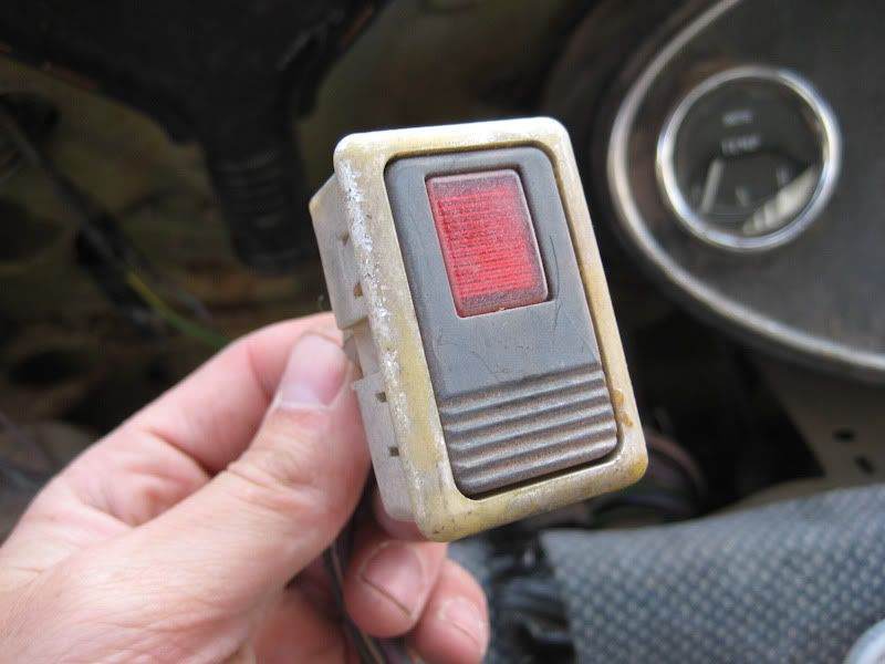
First off, the center chrome button in the center button panel?


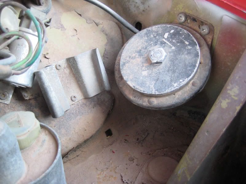
And then this switch.......it doesnt do anything, it was hidden behind the dash tucked under


First off, the center chrome button in the center button panel?
And then this switch.......it doesnt do anything, it was hidden behind the dash tucked under

OVERDRIVE
Joined: Jul 2006
Posts: 7,037
Likes: 283
From: Melbourne, FL
it would help to know your year but I believe your first one is a washer button. not even electrical it is simply a push to squirt button .. matches up to a early 70's owner's manual.....
second one??? hmmmmm can't help on that one ....
second one??? hmmmmm can't help on that one ....


6th Gear
Joined: Dec 2002
Posts: 1,539
Likes: 0
The first button seems non-factory, I believe. Is it an on/off or a momentary switch (spring loaded)? If momentary, it may be an electric washer pump switch. Was your car made in the UK, or elsewhere?
The second button looks like a brake failure indicator test switch.
The second button looks like a brake failure indicator test switch.
OVERDRIVE
Joined: Jul 2006
Posts: 7,037
Likes: 283
From: Melbourne, FL
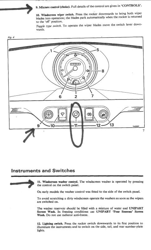
page from the owner's manual of a 69 to 75 850 & 1000
"The second button looks like a brake failure indicator test switch."
hmmm sorry MM I gotta disagree with ya on that one ... every brake test switch I've seen has a picture of a brake pedal on it ... and I've not seen any Lucas switches in white plastic...always black. That looks like a holdover from some non-factory gizmo that's probably long gone but only by tracing the wires would you know for sure. And BTW - the years that had the central washing button didn't yet have the brake test switch anyway....so unless someone tried to ADD that circuit... You know better than me 4 sure but I'm thinking you may have missed this one.
Last edited by Capt_bj; May 28, 2009 at 02:54 PM.
Thread Starter
|
2nd Gear
Joined: Apr 2009
Posts: 95
Likes: 0
From: Colorado
Sooooooo, I tackled the wiring today.....well, I guess you can stay "started" the wiring. I have a freaking disaster ahead of me with this car, but it will be fun!
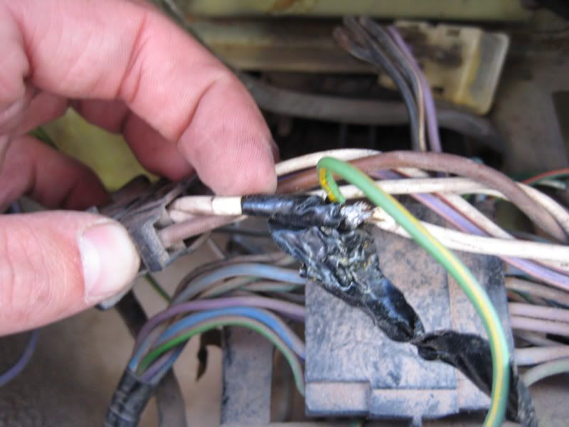
So I found out what the center button does lol, someoen wired it to the horn. Not a very good job at that. They soldered a hack into the ignition wire and then hooked the center button to the button. It wasnt working when I used it because the ground was so corroded it was wasnt grounding out to use it lol
I still havent figured out what this is...
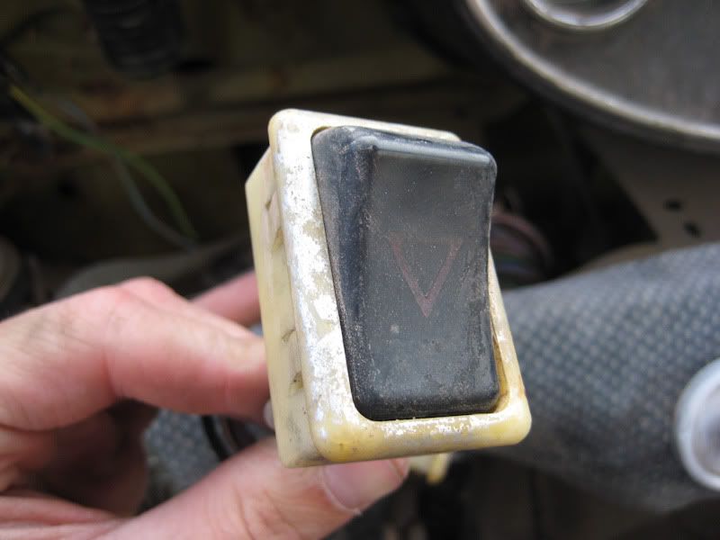
There is also a hazard button that doesnt work
So I found out what the center button does lol, someoen wired it to the horn. Not a very good job at that. They soldered a hack into the ignition wire and then hooked the center button to the button. It wasnt working when I used it because the ground was so corroded it was wasnt grounding out to use it lol
I still havent figured out what this is...
There is also a hazard button that doesnt work
Trending Topics
OVERDRIVE
Joined: Jul 2006
Posts: 7,037
Likes: 283
From: Melbourne, FL
well now is where the REAL fun starts because you have someone who's tried to update the wiring in the car to a later model ... and tried some patches like the horn button so in general the wiring diagrams are just gonna be starting places.
I checked the 69 to 75 1000 Canadian model owner's manual and your switches don't match up to that either .... that is, the two switch panel you have with the button in the middle that I gave u a page for; on the Canada model that panel would have 4 switches, and there'd also be an aux' switch panel by the heater....
according to the MiniMania site
http://www.minimania.com/web/Item/YU.../InvDetail.cfm
"The MK3 Mini had an optional heated rear window; this is the dash mounted switch with pin connectors "
the picture doesn't match but that switch does look like a window heater one so possible it was an attempt to replace a bad one. Are there heater wires in the rear window?
Last edited by Capt_bj; May 29, 2009 at 04:02 AM.
6th Gear
Joined: Dec 2002
Posts: 1,539
Likes: 0
So, it was a momentary switch (aftermarket) someone bodged into the dash.
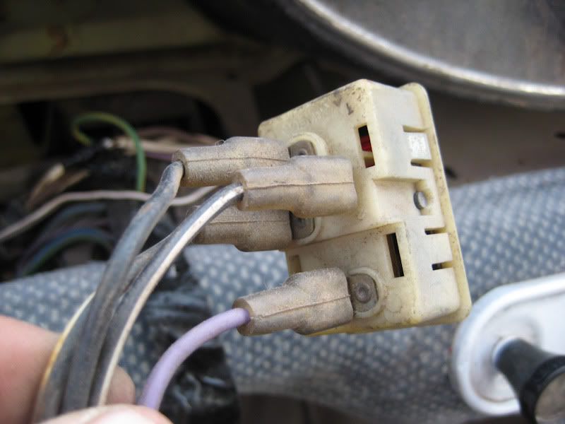
The switches are Lucas. (But maybe not Mini) Red lights were only used for brake failure as far as I know. The similar switch for the rear defogger was yellow lamped, I believe.
Looks like a the car had a short that melted some of the dash wiring harness at some point. See photo of unidentifed red switch, purple wires to the right. I think a PO found a later model wiring harness (5 switches) and placed into an earlier model car with the excess wire/switches tucked under the dash. That's why the aftermarket horn button on the plate. A late model horn switch would be on the turn stalk which his car doesn't have. That's why other switches don't work either.
Last edited by Minimad; May 30, 2009 at 06:09 AM.

4th Gear
Joined: Sep 2007
Posts: 542
Likes: 0
From: Chandler, AZ
Here's a link to some pictures I took during the endeavor ...
Have fun.
Cheers,
Jeff
OVERDRIVE
Joined: Jul 2006
Posts: 7,037
Likes: 283
From: Melbourne, FL
Never give up ....
belay my last and thar she blows ......
I stumbled back into the MK3 owner's manual and what do I find in figure 2:
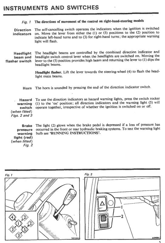
appears sometimes there was an aux switch panel {when installed} and don't those switches look familiar per the drawing... So MM is right, that does appear to be a very early brake test switch.
What we seem to agree on is your wiring is hacked pretty well. Been there and know the feeling... Yes, a new wiring loom is an option and readily available from many sources and if you were doing a complete tear down that certainly would be THE way to go.
On the other hand, you'll be hard pressed to find a car with a more simple wiring system IF you are willing to invest the time to chase the Lucas gremlins as well as the hacks your car has absorbed. Invest in a volt-ohm meter....it doesn't need to be expensive....and learn how to check continuity and resistance. Get a soldering iron and learn how to solder two wires together, and attach a good connector (crimp if yoi like but I solder those too) and how to seal everything with heat shrink tape and/or paint on electrical tape. Look for places the wires have been cut and spliced. If it is wire nuts and tape redo the connection with a soldered connection and heat shrink tape. Splice in new wire if needed. Buy a new fuse box and replace yours and put in new fuses. Examine every connector and replace with new as needed ensuring every connection is clean and tight. Learn how to read the wiring diagrams in Haynes or factory manuals. This is not hard - but IS time consuming. You'll learn a ton about your car in the process.
{ I'd get rid of the carb heater system - it will confuse the issue (I dug for two hours last nite trying to find one...the only reference I can find to a system like that was in an article about the use of the SU in airplanes!)}.
I stumbled back into the MK3 owner's manual and what do I find in figure 2:
appears sometimes there was an aux switch panel {when installed} and don't those switches look familiar per the drawing... So MM is right, that does appear to be a very early brake test switch.
What we seem to agree on is your wiring is hacked pretty well. Been there and know the feeling... Yes, a new wiring loom is an option and readily available from many sources and if you were doing a complete tear down that certainly would be THE way to go.
On the other hand, you'll be hard pressed to find a car with a more simple wiring system IF you are willing to invest the time to chase the Lucas gremlins as well as the hacks your car has absorbed. Invest in a volt-ohm meter....it doesn't need to be expensive....and learn how to check continuity and resistance. Get a soldering iron and learn how to solder two wires together, and attach a good connector (crimp if yoi like but I solder those too) and how to seal everything with heat shrink tape and/or paint on electrical tape. Look for places the wires have been cut and spliced. If it is wire nuts and tape redo the connection with a soldered connection and heat shrink tape. Splice in new wire if needed. Buy a new fuse box and replace yours and put in new fuses. Examine every connector and replace with new as needed ensuring every connection is clean and tight. Learn how to read the wiring diagrams in Haynes or factory manuals. This is not hard - but IS time consuming. You'll learn a ton about your car in the process.
{ I'd get rid of the carb heater system - it will confuse the issue (I dug for two hours last nite trying to find one...the only reference I can find to a system like that was in an article about the use of the SU in airplanes!)}.


4th Gear
Joined: Sep 2007
Posts: 542
Likes: 0
From: Chandler, AZ
-jeff
Thread Starter
|
2nd Gear
Joined: Apr 2009
Posts: 95
Likes: 0
From: Colorado
Thank you guys sooooooooo much!! I was gone all weekend so couldnt reply to the replies! I'll pull alot of the **** tommorow, I do have a wiring diagram in the Haynes manual, but it sounds like getting a factory service manual is the way to go.
Jeff, what model did you go with exactly with your Painless harness? I'm thinking more and more that, that is the option I am going to go with.
Jeff, what model did you go with exactly with your Painless harness? I'm thinking more and more that, that is the option I am going to go with.
4th Gear
Joined: Sep 2007
Posts: 542
Likes: 0
From: Chandler, AZ
The issues that I had with this kit were:
- fuse box placement - I ended up mounting the fuse box in the cabin, behind the parcel shelf directly in front of the left seat (driver in my LHD car). You can see the placement pretty well in the pictures I took. It will not fit on the right hand side due to the ducting for the heater.
- There is no circuit for an electric fuel pump on the 12 circuit harness. There are switched auxiliary circuits, and I'm using one for that purpose.
- I have not yet wired up the windscreen wiper motor. I'm not sure whether there will be any issues with that, but I'm not concerned about that.
One other thing to consider - the Smiths gauges need regulated voltage, and that regulator is part of the speedometer cluster. Both 12v battery and ground connect to the regulator at the speedo, then the regulated power is sent to each of the gauges. I replaced all gauges (except my speedo) with AutoMeter gauges, so I did not care about the regulated voltage. Take digital picturres before you gut the speedo wiring and you should be safe.
Good luck with whatever you end up doing
 . If you need help with understanding the wiring diagram, let me know and I should be able to give you the assistance you need. It was pretty easy though.
Cheers,
Jeff
4th Gear
Joined: Sep 2007
Posts: 542
Likes: 0
From: Chandler, AZ
Nick --
One thing I forgot to mention - you can download the Painless Wiring installation guide as a PDF from their website. Do yourself a favor and read it before you decide that's what you want to do.
As for the flares - I believe they are the City Flare kit that MM sells.
Jeff
One thing I forgot to mention - you can download the Painless Wiring installation guide as a PDF from their website. Do yourself a favor and read it before you decide that's what you want to do.
As for the flares - I believe they are the City Flare kit that MM sells.
Jeff

2nd Gear
Joined: Feb 2005
Posts: 75
Likes: 0
Another thread to resurrect!
It's great to find half my unknown buttons answered here, but I do have a couple more I'm not sure of. One in particular might not even be stock, so who knows?
I think we got this one figured out with the heater controls and windscreen washer button. Unfortunately, that one is borked on mine.

This is the one I'm really wondering about:

I'm pretty sure the **** to the left is for brightness adjustment of the speedometer/dash lights. Obviously, the next item over is the Fasten Belts indicator. The two on the right have been answered above (thanks!) But the switch under the green indicator is my mystery. The indicator is for when the coil has power. My ignition switch is...funky so I have to play with it a bit to get it to catch in the right position so the coil stays powered and the engine continues to fire. The previous owner taught me about this procedure and I will either clean the contacts or install my own toggle switch later so I don't have to worry about losing power when I hit a bump...
But typing of toggle switches, any idea what this three position switch might do? When I flip it, the light will flicker, but seems unaffected whether key-on, off, or while the engine is running.
I'm going outside now to work with the car, but figured I'd post this now and see if anyone has any answers for me by the time I need a break.
Thanks in advance!
It's great to find half my unknown buttons answered here, but I do have a couple more I'm not sure of. One in particular might not even be stock, so who knows?
I think we got this one figured out with the heater controls and windscreen washer button. Unfortunately, that one is borked on mine.
This is the one I'm really wondering about:
I'm pretty sure the **** to the left is for brightness adjustment of the speedometer/dash lights. Obviously, the next item over is the Fasten Belts indicator. The two on the right have been answered above (thanks!) But the switch under the green indicator is my mystery. The indicator is for when the coil has power. My ignition switch is...funky so I have to play with it a bit to get it to catch in the right position so the coil stays powered and the engine continues to fire. The previous owner taught me about this procedure and I will either clean the contacts or install my own toggle switch later so I don't have to worry about losing power when I hit a bump...
But typing of toggle switches, any idea what this three position switch might do? When I flip it, the light will flicker, but seems unaffected whether key-on, off, or while the engine is running.
I'm going outside now to work with the car, but figured I'd post this now and see if anyone has any answers for me by the time I need a break.
Thanks in advance!
2nd Gear
Joined: Feb 2005
Posts: 75
Likes: 0
Still haven't figured out the brake lights, but I have a couple more pics to ask questions about.
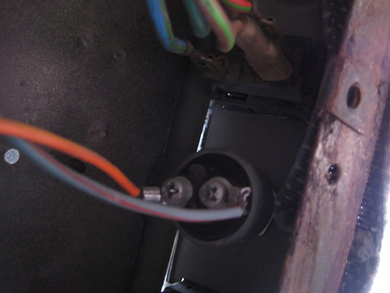
First one I'm really concerned about is this pin I found just sort of dangling from a hole in the transmission. It's loose and I can wiggle and turn it around easily with my fingers, but it does not feel like it has anything to attach to inside. There is a clunk noise when accelerating, but I found the lower ball joint is bad on the passenger side, so I'm pretty sure that's that. But what is this pin? It's the thing right in the center of the photo.

Next is a couple wires hanging below the car near the shifter. One connects to the shifter box and the other two are broken. I don't know if they were meant to connect together or to something else but here they are:


I was really hoping simply connecting them would fix my brake lights, but no such luck...
And on the brake issues, when I went to check the switch at the pedal, it fell apart. I checked continuity between the two wires and they seem to be working at the pedal (I just need to get another switch now) but connecting them does nothing. I also checked the bulbs and they were good. Is there any common fail points for brake lights in the 1980 era mini I should look to first?
First one I'm really concerned about is this pin I found just sort of dangling from a hole in the transmission. It's loose and I can wiggle and turn it around easily with my fingers, but it does not feel like it has anything to attach to inside. There is a clunk noise when accelerating, but I found the lower ball joint is bad on the passenger side, so I'm pretty sure that's that. But what is this pin? It's the thing right in the center of the photo.
Next is a couple wires hanging below the car near the shifter. One connects to the shifter box and the other two are broken. I don't know if they were meant to connect together or to something else but here they are:
I was really hoping simply connecting them would fix my brake lights, but no such luck...
And on the brake issues, when I went to check the switch at the pedal, it fell apart. I checked continuity between the two wires and they seem to be working at the pedal (I just need to get another switch now) but connecting them does nothing. I also checked the bulbs and they were good. Is there any common fail points for brake lights in the 1980 era mini I should look to first?
OVERDRIVE
Joined: Jul 2006
Posts: 7,037
Likes: 283
From: Melbourne, FL
looking at the owner's manual for 1980, it appears that panel held among other things the switch for the rear fogs if fitted. I'm gonna guess that the car did not originally have rear fogs but someone did a mod and added them putting the switch there - but not a matching factory switch - and the remains of that wiring is what you see . . . just a guess tho. I lean this way because I've never seen a Mini of this vintage with a dash dimmer either, no mention in any owner's manual I have, so I'm guessing this was another 'mod' added by an owner/electrician (or not)
on the flip sign I don't see a reference to a seat belt warning down there either so maybe this is not a UK build ... I'll check Canadian references
***additional***
thar she blows - yes I now see the seat belt warning and a dimmer in the Canada Mini 1000 manual for 76 thru 80 . . .
on the flip sign I don't see a reference to a seat belt warning down there either so maybe this is not a UK build ... I'll check Canadian references
***additional***
thar she blows - yes I now see the seat belt warning and a dimmer in the Canada Mini 1000 manual for 76 thru 80 . . .
Last edited by Capt_bj; Jun 28, 2011 at 05:40 AM.

I would get a ohmmeter and ring those green danglies to ground and see if that's what they are. First off, green is used for ground many times, and when people that don’t know what they're doing try to fix sound issues with stereos sometimes they go hunting for earth for grounds. My guess is that they struggled to tie grounds together to solve some problem and didn’t bother to clean up the experiment when they were through.
OVERDRIVE
Joined: Jul 2006
Posts: 7,037
Likes: 283
From: Melbourne, FL
thar she blows ..... again .....
does this look familiar?
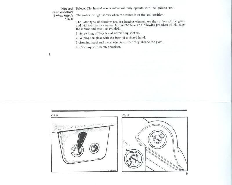
1969 to 1975 850 and 1000 Handbook (aka Owner's Manual)
looked more closely of your mystery wires underneath and see some crimp connectors of a VERY un-Lucas like type. This stuff appears to be a hack and I'd get rid of all of it.
does this look familiar?
1969 to 1975 850 and 1000 Handbook (aka Owner's Manual)
looked more closely of your mystery wires underneath and see some crimp connectors of a VERY un-Lucas like type. This stuff appears to be a hack and I'd get rid of all of it.
Last edited by Capt_bj; Jul 2, 2011 at 01:30 PM.