Drivetrain 2005 MCS R53 Electric Water Pump / TPI Harmonic Balancer
#51
 12-04-2014, 05:32 PM


RiverCity, I don't know off-hand that bolt size. I'll try to check the Bentley manual later though...
Sorry to hear about the issues you have been experiencing. I didn't encounter such. I connected to a previously used switched power "Add-a-Circuit" I had in the fuse box, as you show above. Constant power I used the 12 volts there by air filter box. Works like a champ.
Hope you get all sorted-out soon...
#52
12-05-2014, 04:18 PM

2nd Gear
So, I wired the pump to a switch and mounted it under the steering column. It's not ideal, but it works. Bled the cooling system, added coolant, and took her out. I drove around the neighborhood for about an hour, went through some stop and go traffic, all in all about 18 miles and the temp gauge never broke the 1/2 way mark. No leaks I can see.
So far things are looking good.
So far things are looking good.
#53
01-04-2015, 06:49 PM
I never saw your post until just today, almost 2 months later, I got this in my email at 7:51 am today:
Dear TonyB,
Pablopaha has just replied to a thread you have subscribed to entitled - 2005 MCS R53 Electric Water Pump / TPI Harmonic Balancer - in the Drivetrain (Cooper S) forum of North American Motoring.
This thread is located at:
https://www.northamericanmotoring.co...8&goto=newpost
Here is the message that has just been posted:
***************
Hey Tony, your setup looks good. I'm waiting on some bits to arrive so I can do the EWP mod also. Have you fitted yours yet? Do you have any pics? Have you noticed much of a difference?
Cheers
Paul
***************
Strange. My apologies...
Yes, all installed for several weeks and working like a champ. Temps are down, but it's winter here though... I also removed the A/C at the time, installed an aftermkt all aluminum radiator, serviced the SC, new serpentine belt, ditched the stock seats, and installed just one aftermkt one. I shed a fair amount of weight and did other stuff, not just the EWP, so I feel a difference alright, but how much is attributable to the EWP is unknown.
I Seafoam'd the car today (fuel, oil and air intake systems), cleaned the air filter, oil / oil filter change, spark plugs / wires and the car is running very well. I had previously cleaned-out the IC (w/ brake cleaner) and of course have new coolant in the system. Good to go for a while now...
There was no way I'd be going back to the stock water pump after what I experienced at just 60k miles, and others too. I think I took a couple pics, and I believe I put them in my gallery. If not, I'll share...
Last edited by TonyB; 01-04-2015 at 07:48 PM.
#54
01-05-2015, 03:05 PM

Is anything stopping me from using this pump?
http://www.summitracing.com/parts/sum-316000/overview/
Cheaper rated for same flow, right?
http://www.summitracing.com/parts/sum-316000/overview/
Cheaper rated for same flow, right?
#55
04-12-2015, 05:06 AM

1st Gear
Join Date: Feb 2014
Location: Australia
Posts: 35
Likes: 0
Received 0 Likes
on
0 Posts
EWP on 2006 R53
I've been ordering parts over the past few months in preparation to convert to a Davies Craig EWP. Along with the EWP I've fitted a rebuilt supercharger sans the PTO gears, alloy radiator, new drive belt, crank position sensor O ring and the ALTA tension stop.
The main reason I did the conversion was as a preventative measure, to ditch the PTO gears before they started causing trouble. I did the rest of the mods because it seemed like a good time to do it, with everything apart.
Well, the old supercharger was in perfect condition....the gears were perfect and the oil was fairly decent, a caramel colour rather than black, and there was plenty of it. The new supercharger slotted in and everything went together pretty well.
I've kept the thermostat with the EWP rather than use a controller and the coolant gets to operating temp nice and quick and settles perfectly.
I wasn't expecting a huge difference from the EWP but the improvement in low down throttle response is very noticeable! First and second gears in particular are much snappier than with the mechanical pump.
I think this is a very worthwhile conversion and with the parts on hand should only take a weekend to complete.
#57
09-10-2015, 06:48 PM

Neutral
Join Date: Sep 2015
Location: Las Vegas, NV
Posts: 4
Likes: 0
Received 0 Likes
on
0 Posts
Pablopaha -
I never saw your post until just today, almost 2 months later, I got this in my email at 7:51 am today:
Dear TonyB,
Pablopaha has just replied to a thread you have subscribed to entitled - 2005 MCS R53 Electric Water Pump / TPI Harmonic Balancer - in the Drivetrain (Cooper S) forum of North American Motoring.
This thread is located at:
https://www.northamericanmotoring.co...8&goto=newpost
Here is the message that has just been posted:
***************
Hey Tony, your setup looks good. I'm waiting on some bits to arrive so I can do the EWP mod also. Have you fitted yours yet? Do you have any pics? Have you noticed much of a difference?
Cheers
Paul
***************
Strange. My apologies...
Yes, all installed for several weeks and working like a champ. Temps are down, but it's winter here though... I also removed the A/C at the time, installed an aftermkt all aluminum radiator, serviced the SC, new serpentine belt, ditched the stock seats, and installed just one aftermkt one. I shed a fair amount of weight and did other stuff, not just the EWP, so I feel a difference alright, but how much is attributable to the EWP is unknown.
I Seafoam'd the car today (fuel, oil and air intake systems), cleaned the air filter, oil / oil filter change, spark plugs / wires and the car is running very well. I had previously cleaned-out the IC (w/ brake cleaner) and of course have new coolant in the system. Good to go for a while now...
There was no way I'd be going back to the stock water pump after what I experienced at just 60k miles, and others too. I think I took a couple pics, and I believe I put them in my gallery. If not, I'll share...
#58
09-11-2015, 01:22 AM
1st Gear
Join Date: Feb 2014
Location: Australia
Posts: 35
Likes: 0
Received 0 Likes
on
0 Posts
EWP fitted
I fitted my EWP in April.
While I was at it I also replaced my supercharger with a re-built one, fitted an alloy radiator with drain plug, new drive belt and new O ring for the crank position sensor.
I live in the tropics and the EWP works great! From 2800rpm throttle response is much snappier! There's no way I'd go back to the OEM water pump.
When I had the supercharger re-built I had the large drive gear removed from the PTO and a blanking disc fitted to seal the PTO.
Although the EWP is small it's still a very tight fit.
If you wire the EWP from Sprintex wiring diagram for their setup, the water pump continues to run for approx 3 minutes after the engine is turned off which helps with heat sink.
#59
10-04-2015, 12:49 PM

So, I wired the pump to a switch and mounted it under the steering column. It's not ideal, but it works. Bled the cooling system, added coolant, and took her out. I drove around the neighborhood for about an hour, went through some stop and go traffic, all in all about 18 miles and the temp gauge never broke the 1/2 way mark. No leaks I can see.
So far things are looking good.
So far things are looking good.
#60
10-04-2015, 06:47 PM
1st Gear
Join Date: Feb 2014
Location: Australia
Posts: 35
Likes: 0
Received 0 Likes
on
0 Posts
EWP mount
Hi Timmy,
unfortunately the laptop that had all of my pictures on died and I lost everything.
I'll be doing an oil change this afternoon so I'll try to get my camera in there to get some pics.
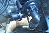
PTO blanking plate. The large gear was removed along with the bearing and fork drive which left a hole in the middle of the PTO. A 4mm aluminium disc was cut and 4 holes drilled in to it to cover the hole and it was bolted in place on the outside of the PTO and sealed with some silicone gasket.
The small gear was left in place and the PTO is still filled with oil to keep the seal mist.
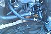
Water pump. I was planning on making a mount for the EWP but it is very snug where it sits so I've just zip tied it in place so that it doesn't vibrate too much. The coolant hoses hold it in position.
unfortunately the laptop that had all of my pictures on died and I lost everything.
I'll be doing an oil change this afternoon so I'll try to get my camera in there to get some pics.
PTO blanking plate. The large gear was removed along with the bearing and fork drive which left a hole in the middle of the PTO. A 4mm aluminium disc was cut and 4 holes drilled in to it to cover the hole and it was bolted in place on the outside of the PTO and sealed with some silicone gasket.
The small gear was left in place and the PTO is still filled with oil to keep the seal mist.
Water pump. I was planning on making a mount for the EWP but it is very snug where it sits so I've just zip tied it in place so that it doesn't vibrate too much. The coolant hoses hold it in position.
#61
10-05-2015, 03:46 AM
1st Gear
Join Date: Feb 2014
Location: Australia
Posts: 35
Likes: 0
Received 0 Likes
on
0 Posts
EWP pictures
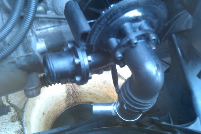
Here are some pictures of the EWP conversion I found on the net.
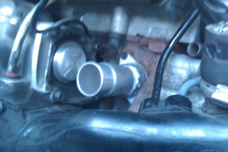
You'll need to use the coolant inlet fitting between the OEM water pump and the block and weld some 32mm pipe to it that the coolant hose can attach to. You can see a blanking plate on the back of the supercharger in the picture.
You'll need to make a T-piece (aluminium) with the main piece being 32mm with an 18mm coming in to the side of it. This T-piece will sit between the bottom outlet of the radiator and the inlet of the EWP so it needs to be as short as possible as there's not a real lot of space. The 18mm hose will run from the thermostat housing to the T-piece.
You'll need to check out an auto store for some hoses that will fit the new arrangement as the OEM ones won't fit with the EWP.
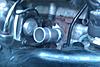

#62
07-06-2016, 08:37 PM

Ok first time poster, know this is older thread, but thought I share installing EWP80 in 2005 R53.
Installing an electric water pump in Mini R53
Daughter and boyfriend Keegan arrived at Ranch in a 2005 Mini Cooper S(R53) They were traveling around the country from NYC.

I immediately noticed noise coming from the front of the engine and thought timing chain. Turns out it was the supercharger, more specifically the water pump gears driven by the supercharger. These gears are notorious for failure due to bad design in shaft bearing and seals. The seal goes bad and the vacuum on the supercharger sucks out the oil and the gears then run dry and turn to metal dust. As they destroy themselves they make lots of noise.
BMW, the maker of the Mini confirmed the supercharger was faulty and wanted $6,600.00 to replace. They found additional problems like both drive axles and wanted $13,000.00 to fix all. A rebuilt supercharger costs between $900-$1,600.00 and doesn�t address the poor design issues with the water pump and seals.
Keegan and I decided to do the work ourselves and initially wanted to rebuild the WP drive gear box, but the gears are hard to come by and the total cost would have been ~$500.00. Neither BMW or Eaton the maker of the Supercharger sell rebuild kits. The gears are only available by 3rd parties who make them.

In researching the issue, we decided to replace the water pump with an electric water pump, specifically an Davies Craig EWP80. We found a guy selling one on EBay who was local and bought it for $220.00.
We managed to strip the car in ~4.5 hours removing the supercharger.
We also bought both front axles ($162.00), and installed them. Replaced some O-rings and a few other sundry things.
In order to install the electric water pump, I needed to design and fabricate a couple of pieces as mounts. There are only a couple of places where you can install this pump, and I decided to install in roughly the same position as the original. In fact, all of the original hoses are reused.
There is simply no space in the engine compartment.
First we modified the supercharger by making an end plate from 1/4� aluminum plate and removing the gears and water pump.
However, designing and fabricating the actual mount proved to be very difficult. It involved 3 different �planes� and interrelated angles.
The first version was off by 1/8� hitting the supercharger.
On my second attempt, some bad welding and the mount still touching the new end plate of the supercharger nixed that attempt.
Third time is a charm as they say. I managed to weld up the mount, moving the new water pump over by more than a 1/4� and getting everything to fit.

Talk about alien 3D geometry only solvable by standing on head while welding;p


Wired EWP to the number 5 pin in the engine compartment fuse box. Pump functions great, and runs for ~2 minutes after shutting off engine. I ended up soldering the connection as the junction clip would not allow the cover on the ECU to close. Solder works and everything looks good.
Everything working great. Normal temps while driving. EWP spins full speed while stuck in traffic unlike belt driven pump. EWP also unloads supercharger, so it responds faster. Gain in horsepower is estimated to be 5-8HP.
Total cost of repairs/mods ~$500.00 including new axles, EWP and several other minor things.

#64
07-07-2016, 05:54 AM

2nd Gear
Join Date: Jun 2016
Location: Virginia Beach
Posts: 56
Likes: 0
Received 0 Likes
on
0 Posts
#65
07-19-2016, 10:17 AM
Thanks Greg for the well-written post on your installation  .
.
Since this is the most complete documented attempt we've seen, we now feel obligated to share some of our installation insights in case they're helpful.
First, a few big disclaimers: this is only for R53/R52 with an automatic transmission and is still in the long-term testing phase (still lacks winter weather and full vibration testing such as driving on gravel roads), but that's ok since at this point most of the views on this topic are from others willing to test on their own cars . As such, when long-term testing is completed by end of this year, this will be completely published on the Imperial MINI website (next to the more inexpensive MCS Recharger System). Note, the hydraulics from that system are still needed and used to replace the contaminated SC oil on the belt-side of the SC w/o any disassembly. And the last disclaimer, for manual transmissions (>95% of all R53s), most of the EWP conversion info posted in this thread is correct, except for the lack of a controller which is briefly addressed for the following installation.
Parts:
Davies Craig EWP Kit 8807 ~$250 + shipping from AU (eBay)
Dorman Hose Connector T 627-006 $11
MINI Hose Connector elbow 17127515487 $6
MINI Waterpump Connection Flange w/ o-ring 11517509170 $18 (optional, so you can have the new one welded with bung ahead of front-end removal and ready for install with new o-ring)
Hose Connector Bung, 1.25" Dia ~$7 (vary in prices, we use actual barbed radiator hose bungs but a cheaper beaded pipe style will work provided the clamp is properly seated- which is hard to see in that cramped area)
MINI Hose Connector 17127515502 $10
MINI Hose Connector Clamps 17127520888 qty 10 ~$43 (optional, cheaper stainless steel ones can be used but not preferred in areas where critical coolant hoses are placed close together)
Gates Radiator hose, short upper 23378 $12
Gates Heater Bypass hose 5/8" x 2.5 ft $4
Gates Heater Bypass hose 3/4" x 3" $1
Dorman Help Heater Hose Connector 47080 5/8" x 3/4" $3
Gates T-Stat 33849 $3.50 (optional, if you prefer to replace and prepare it ahead of time)
Fel-Pro T-Stat seal $6.50
ATO Add-A-Circuit $7
ATO 1A Fuse Pack $5
Protective Wire Wrap 1/4" x 14ft Chicago Electric 66985 $3
Bolts, electrical tape, teflon tape, plastic ties and other misc parts
No crazy welding nor parts fabrication are necessary and the Davies Craig instructions can be followed provided the EWP is installed similar to this way. Other benefits include:
- Better cooling, since the EWP is mounted lower, it gets more air circulation than being crammed in next to the hot SC and intake.
- You can easily bleed the air from the EWP like in the instructions, unlike the OE location which can leave air in the EWP inlet and dry out the seals (and void the warranty!).
- The SC end plate does NOT need to be modified, just remove it and take it to the same machine shop with the bung. Either an arbor or 14 ton small press can be used on the inside spindle to push it down and out of the gear. Then the spindle is just pressed back into the plate by flipping the plate over so the inside is facing down. Reinstall the plate, remove the drain/fill plug and add 1.5 oz of new SC oil to keep the PTO seal from drying out. We also install a neodymium magnet on this plug since it's being permanently reinstalled. Also, change the snout end SC oil before reinstalling the SC.
Install notes:
- The bung weld can be easily accomplished on the outside of the flange and shown below is a rough example of what you should at least expect to get accomplished with a guarantee that if you detect a leak, you can bring it back for touch up.
Tip: ask the welder if he has some penetrator leak test oil he can use on the back of the weld seam before you take it.
- Patience is definitely a virtue during the careful rerouting/reuse of the OE hoses and electrical cables The EWP cable can be tied to the alternator cable and followed back around the ECU and thru the firewall to the controller which we install beneath the steering wheel near the ODB2 port (where a scangauge2 is permanently installed to monitor actual temps).
- The t-stat is removed and two 5mm holes drilled into it, then it's reinstalled. This will allow operating temps to be maintained using the controller as we've found during long-term testing on the manual transmission R53s.
- The EWP relay wire (green wire if using the controller) should NOT be wired or soldered directly onto the ECU pin 5. Even the DC instructions do not recommend this- instead it's wired into the Add-A-Circuit fuse holder with one of the 1A fuses, into the 2nd 20A slot from the front of the accessory engine bay fuse box. The fuse box cover still closes after the fuse holder wire is routed thru the bottom of the front opening, and the EWP continues to run for a few minutes after engine shutoff.
.Since this is the most complete documented attempt we've seen, we now feel obligated to share some of our installation insights in case they're helpful.
First, a few big disclaimers: this is only for R53/R52 with an automatic transmission and is still in the long-term testing phase (still lacks winter weather and full vibration testing such as driving on gravel roads), but that's ok since at this point most of the views on this topic are from others willing to test on their own cars
. As such, when long-term testing is completed by end of this year, this will be completely published on the Imperial MINI website (next to the more inexpensive MCS Recharger System). Note, the hydraulics from that system are still needed and used to replace the contaminated SC oil on the belt-side of the SC w/o any disassembly. And the last disclaimer, for manual transmissions (>95% of all R53s), most of the EWP conversion info posted in this thread is correct, except for the lack of a controller which is briefly addressed for the following installation.Parts:
Davies Craig EWP Kit 8807 ~$250 + shipping from AU (eBay)
Dorman Hose Connector T 627-006 $11
MINI Hose Connector elbow 17127515487 $6
MINI Waterpump Connection Flange w/ o-ring 11517509170 $18 (optional, so you can have the new one welded with bung ahead of front-end removal and ready for install with new o-ring)
Hose Connector Bung, 1.25" Dia ~$7 (vary in prices, we use actual barbed radiator hose bungs but a cheaper beaded pipe style will work provided the clamp is properly seated- which is hard to see in that cramped area)
MINI Hose Connector 17127515502 $10
MINI Hose Connector Clamps 17127520888 qty 10 ~$43 (optional, cheaper stainless steel ones can be used but not preferred in areas where critical coolant hoses are placed close together)
Gates Radiator hose, short upper 23378 $12
Gates Heater Bypass hose 5/8" x 2.5 ft $4
Gates Heater Bypass hose 3/4" x 3" $1
Dorman Help Heater Hose Connector 47080 5/8" x 3/4" $3
Gates T-Stat 33849 $3.50 (optional, if you prefer to replace and prepare it ahead of time)
Fel-Pro T-Stat seal $6.50
ATO Add-A-Circuit $7
ATO 1A Fuse Pack $5
Protective Wire Wrap 1/4" x 14ft Chicago Electric 66985 $3
Bolts, electrical tape, teflon tape, plastic ties and other misc parts
No crazy welding nor parts fabrication are necessary and the Davies Craig instructions can be followed provided the EWP is installed similar to this way. Other benefits include:
- Better cooling, since the EWP is mounted lower, it gets more air circulation than being crammed in next to the hot SC and intake.
- You can easily bleed the air from the EWP like in the instructions, unlike the OE location which can leave air in the EWP inlet and dry out the seals (and void the warranty!).
- The SC end plate does NOT need to be modified, just remove it and take it to the same machine shop with the bung. Either an arbor or 14 ton small press can be used on the inside spindle to push it down and out of the gear. Then the spindle is just pressed back into the plate by flipping the plate over so the inside is facing down. Reinstall the plate, remove the drain/fill plug and add 1.5 oz of new SC oil to keep the PTO seal from drying out. We also install a neodymium magnet on this plug since it's being permanently reinstalled. Also, change the snout end SC oil before reinstalling the SC.
Install notes:
- The bung weld can be easily accomplished on the outside of the flange and shown below is a rough example of what you should at least expect to get accomplished with a guarantee that if you detect a leak, you can bring it back for touch up.
Tip: ask the welder if he has some penetrator leak test oil he can use on the back of the weld seam before you take it.
- Patience is definitely a virtue during the careful rerouting/reuse of the OE hoses and electrical cables
The EWP cable can be tied to the alternator cable and followed back around the ECU and thru the firewall to the controller which we install beneath the steering wheel near the ODB2 port (where a scangauge2 is permanently installed to monitor actual temps).- The t-stat is removed and two 5mm holes drilled into it, then it's reinstalled. This will allow operating temps to be maintained using the controller as we've found during long-term testing on the manual transmission R53s.
- The EWP relay wire (green wire if using the controller) should NOT be wired or soldered directly onto the ECU pin 5. Even the DC instructions do not recommend this- instead it's wired into the Add-A-Circuit fuse holder with one of the 1A fuses, into the 2nd 20A slot from the front of the accessory engine bay fuse box. The fuse box cover still closes after the fuse holder wire is routed thru the bottom of the front opening, and the EWP continues to run for a few minutes after engine shutoff.
Last edited by M1N1-Me; 09-13-2016 at 02:44 PM. Reason: Added 1A Fuse Pack
#66
07-19-2016, 10:44 AM

I thought I saw somewhere that the pump life on these ewp80's was some stupid low number such as 400 hours. but I guess that has changed. they are claiming now 2000 hours, which is much more respectable. nice to have a huge post about this conversion.
then for it to draw only 7.5 amps, that's also awsome
then for it to draw only 7.5 amps, that's also awsome
#67
07-24-2016, 09:32 AM
Hi all, please forgive some rambling thoughts from and old geaser/greaser
I mean this only as a discussion and to give back to the community, since I appreciate the helpful insights while repairing the r53. I wish to cause no offense, merely have a beer and share ideas. I also don’t think I will be a long time contributor here as I don’t own a Mini and may never see the one I worked on again.
First I am not a certified mechanic, but have done repair and maintenance work my entire life, so over 5 almost 6 decades of grease under the fingernails. This includes repair n maintenance on equipment in a family owned laundromat/drycleaners, racing go carts/motorcycles, teen street rods, classic and antique auto restoration, now farm/ranch maintenance. Throw in lots of building maintenance, computers and other life experiences. I also enjoy building and modifying things, and in general dislike poorly designed things. I’m not trying to brag here, only attempting to indicate level of competence. Plus I'm just a cheapskate and don't like spending $$ if I don't have to!
Since I want to share thoughts, opinions and results of research I did while working on this Mini, a disclosure… Take everything you read on the Internet with a pound of salt, do your own research, and most definitely proceed with any procedures at your own risk. My sharing comes with no implied warranties/guarantees.
So working on the Mini was actually interesting and fun. Last time I worked on and drove a Mini was late 60’s on a friend’s 64. The biggest problem was the time pressure to get them on the road again. Gotta say, driving a Mini is a blast, so see why the enthusiasm. Reminds me of cart racing, and I used to own a Honda 600 that handled corners well. It did not have the HP so stomping on it wasn’t the same.
IMHO the whole design of the water pump driven off the SC is a poor design. I think if I owned a Mini, I would install an electric WP as a mod just to correct the potential problems it causes and to improve the car. Unloading the SC gives you more power especially in low to mid ranges, improves cooling, especially while idling after a fast run, and hopefully increase the longevity of the engine. Guess we will just have to see.
Speaking of longevity, this SC/WP wasn’t very old in r53 I worked on. Keegan bought the Mini used from a Mini dealer and had the SC replaced under warranty maybe a couple of years ago. Not sure of actual mileage.
I am grateful for the folks who did this before I did. After researching, I think the Davies Craig EWP80 is a fine product, was impressed by the company and engineering. Lots of folks don’t care for “Plastic” anything in a car, but it is a fact of life, so all that is left is making sure that the “Plastic” (generic term here) is up to the task. Look at the specs, see if you find lots of reported problems (isn’t the internet great for that?) and then decide.
So what kind of “Plastic” is the EWP80 made from and is it up to the task?
According to DC site, it is Nylon 66 with 30% glass fiber fill. Actually you can find specs on this composite and the specs are very good. This is used in lots of pumps and fittings and has a good service record. The specs are for sheet material, and when you mold it with curves, ribs, etc… the results typically improve overall performance.
Next question is the manufacture, does it have a good record and quality control. In this case I think so. Yep, you can find folks who have issues, but in general lots of folks using them and see good results. Sprintex is using them, and despite any issues with their SCs(?) don’t hear that many complaints about the EWP. Can’t say I like the mounting system Sprintex has come up with, but each their own.
If you don’t like the EWP80, get another model or brand. I still think an electric pump makes sense in general and removing the SC load is a great idea. As soon as I saw the WP on the back end of the SC, I thought, huh, who would want to cripple a device that is supposed to boost hp with a big parasitic load? I actually did not mention the idea of modding his Mini, but Keegan read some of the same stuff on line and asked me what I thought. I said I thought it was a great idea.
Since my ramblings are here about the problems with the SC driving the WP, I think that the problems are even greater than just the seal on the backside of the little drive gear. Not only were the gears chewed up, but I see a lot of wear on the actual PTO forked gear. There is a lot of pressure and torque differences between a belt driven super charger and then the constantly changing pressures for moving water. Each tap of the accelerator creates a differential load as the water ramps up. I would think this would also increase the wear and tear on the serpentine belt and pulley assembly.
What do you think?
There are some folks who say the increased load on the alternator would offset any hp gains with an EWP. This argument just doesn’t hold water. Not only proven on dynos all over the place, but look at the amp draw and you can do the math. The EWP80 draws a max of 7.2 Amps, but typically draws 2-3 amps. Any modern alternator can handle this “extra” load, and remember alternators are designed of maximum load of the respective vehicle and not everything is on at once. Indeed Keegan’s Mini doesn’t have heated seats and some other extras, so lots of spare amp load available. We did not of course dyno his car.
What about the engine heat? The specs even for flat sheet material is well within the temps found in an engine compartment. The DC spec sheet list operating temps of -20C to 130C (-4F - 266F). I’d be more concerned about freezing than over heating. The concerns of installing the EWP in space with better air circulation is also misplaced IMO. Nylon is an insulator, and as far as temp effects, the water circulating inside will have a greater affect than the any difference in location in air stream inside engine compartment especially installed past the radiator. Water cooling vs air cooling, no contest, just look at water cooling inside computers vs a fan. There is also the fact of thermo transfer with conduction, the water coming into the EWP is post radiator cooling, and it is still receiving air on the outside.
Mini-Me, is there really a temp difference between locating the pump near supercharger vs an alternator? How much? Intake airbox hot?
IMHO this is a red herring/myth and a non factor for installation location.
Also not crazy about putting a water pump next to alternator in case of leaks.
So Mini-Me is showing a different location and orientation for his proposed mods. Hey great, there are really very few locations to even place this, so finding anther possibility is good.
Don’t think the temp consideration holds up, but what about orientation? Might in fact be a better solution especially for “bleeding” the air out of system.
Bleeding is mostly a one time issue after draining coolant. Yep, worried about this somewhat. DC gives specific instructions about it and if you install like I did, you could have the potential of trapping some air in the outlet horn. If you are careful while filling, I think this is not a real problem. Believe me, watching the temp gauge will tell you soon. Assuming you installed the pump on the bottom radiator hose, you are sucking water, not pushing air. If you notice, the bleed valves are on the top hose, more difficult to bleed from here and you don’t want to create air blockage here and the air can compress while being “pushed”.
There is also the fact that air over time will get self purged, either from turbulence or from absorption into the water and released in the expansion tank. Having said this, please make sure not to trap air, watch your gauges and if all else fails you can apply suction on the upper hose connections to help purge air. Really don’t think it will be needed.
Just as an aside, have you ever seen how many crevices, and other areas inside an engine water jacket there are for trapping air?
All good my friends.
Hey Mini-Me, aren’t you a famous movie star?
OK, what about wiring it up. Mini-Me, not meaning to pick on you, but want to address some things you wrote.
Seems you are critical of attaching the “green” wire to the #5 pin in the fuse box loom. Please tell me why?
I actually followed the Sprintex instructions, and I’m not seeing any reported problems and didn’t see any issues after hooking it up. So is there a real issue? Love to know.
You also seem critical of soldering?? Why please?
So I did initially attempt to use the included splice/jumper connector, but given the location of the #5 pin wire, the connector interferes with the loom jacket and compression hump. So after detaching the loom connector, removed the crimp connector and removed wire insolation and soldered the “green” wire in. Then I taped the joint and it gets covered by the loom jacket and now the fuse box cover will close.
While I use these types of splice connectors all the time, there are some drawbacks. In the vast majority of times when you use them, some of the strands of wire will be severed. I’d say this is true about 90% of the time, as was the case here. They are just convenient, not necessarily the best splice connection. Not that I have had any real issues using them, unless I have to remove and reinsert them for some reason. Still feels like cheating.
IMHO soldering is a superior method and I do it all the time to electronic circuits. Not sure if concern here is zapping the computer by soldering or not, but really none issue with proper soldering iron. There are far greater potential Electrostatic Discharge that could zap your computer all over the engine bay, Plugs, wires, bad ground.
Not sure about your connections (who you are) and if you are intending to create a commercial mod package. More power to you. Are you connected to Imperial Mini?
I do have some concerns with your stated methods for wiring the “green” wire. You are aware this is just the low current (energizer) wire for the relay coil, are you not? The low side is not connected to the “High Current” side (the Red wire) which is then contacted to “blue” pump wire. The red wire does need a fuse.
The low side of relays use very little current, milliamps ; ~120-160mAmps@12v. If you are indeed connecting this to a 7.5Amp fuse, that is no protection at all. A knife fuse will NOT “blow” until it receives ~double the constant rate or in this case ~15amps. Man if the coil inside the relay gets hit with that, you got lots of other issues, not to mention a fried loom.
If you really want to fuse this, IMHO you are looking at a 1 amp fuse or there abouts’.
Again please don’t take my word for this, but maybe investigate it, OK.
Have lots of other ideas concerning the Davies Craig pump controller, is it really needed? No Is it over priced? Think so,
I can get programmable controllers on EBay or Amazon for less than $20.USD that can do everything the DC controller does and more.
Can you make the pump variable speed and control with thermosistor? Think so.
I was either going to do this or use a temp switch to delay pump start, then found wording on DC that says not to do this and advised to just run pump with a hole in T-stat.
“The EWP may be used with a Davies, Craig Thermal Switch (Part Nos. 0401 and 0402) as an auxiliary pump. If the EWP is the only pump in the engine it should not be run with an on/off thermal switch like a radiator fan. Your engine needs some flow all the time or hot spots will form outside the cylinders.“
DC recommends drilling a 5mm hole. Did this by cutting off the jiggle plug on t-stat and drilling out hole slightly larger. Be careful to leave enough meat on the t-stat where you drill or you may weaken the unit. Also make sure any hole you drill will not get covered by the gasket.
The DC controller uses a pulsed on off at 6 Volts (half speed) until the temps come up and then it ramps up to 12volts continuous running.
There are some other information on the site saying running EWP80 full time with t-stat in place is fine, mostly in the FAQs but DC doesn’t make this easy and makes it seem like you have to buy their controller and remove stock thermostat.
Spend your money as you see fit. I can see benefits to a controller, but think it is added bling with some potential additional complications. But all mods are like that, are they not?
And just so everyone knows, I was trying to be humorous about the welding. I really didn’t have to stand on my head.
Enough Ramblings
Have fun everyone!
Now where can I find a “Free” Mini
Greg
The following users liked this post:
Mini Devil (12-02-2019)
#68
07-26-2016, 02:15 PM
If you don’t like the EWP80, get another model or brand. I still think an electric pump makes sense in general and removing the SC load is a great idea. As soon as I saw the WP on the back end of the SC, I thought, huh, who would want to cripple a device that is supposed to boost hp with a big parasitic load? I actually did not mention the idea of modding his Mini, but Keegan read some of the same stuff on line and asked me what I thought. I said I thought it was a great idea.
Since my ramblings are here about the problems with the SC driving the WP, I think that the problems are even greater than just the seal on the backside of the little drive gear. Not only were the gears chewed up, but I see a lot of wear on the actual PTO forked gear. There is a lot of pressure and torque differences between a belt driven super charger and then the constantly changing pressures for moving water. Each tap of the accelerator creates a differential load as the water ramps up. I would think this would also increase the wear and tear on the serpentine belt and pulley assembly. What do you think?
Since my ramblings are here about the problems with the SC driving the WP, I think that the problems are even greater than just the seal on the backside of the little drive gear. Not only were the gears chewed up, but I see a lot of wear on the actual PTO forked gear. There is a lot of pressure and torque differences between a belt driven super charger and then the constantly changing pressures for moving water. Each tap of the accelerator creates a differential load as the water ramps up. I would think this would also increase the wear and tear on the serpentine belt and pulley assembly. What do you think?
 Yes, we've seen destroyed gears that ran dry of oil, but never seen any fork gear damage, at least that caused any gear backlash greater than any other SC/waterpump- and we've tested backlash on every SC along with the compression test.
The 5-8 HP gain estimate seems exaggerated based on our results of the EWP conversions. Hardly makes any noticeable difference in low gear throttle response, about the same kick as a DT bypass valve

The main realized benefits of a controller based EWP conversion is to increase the probability of engine longevity (since long-term testing is still ongoing, this can only be estimated from the cooler operating temps) and at the same time eliminating one of the more expensive repairs of the R53 reliability weaknesses; the PTO gears. Other reliability issues include failed top engine mounts causing premature clutch wear/failure, PS pump shorts leading to smoldered connectors/engine fires, crank pulley failures, A/C clutch diode/open-circuits, leaking plastic coolant expansion tanks, open low-speed radiator fan resistors, and after hearing about only one of these, the countless repeated responses "I'll never buy a MINI!"). Yet, the 1st gen MCS is still the most affordable of the bunch after all the repairs/preventative maintenance, and only one with a non-interference engine (at least we sleep better each night telling ourselves this, right?).
What about the engine heat? The specs even for flat sheet material is well within the temps found in an engine compartment. The DC spec sheet list operating temps of -20C to 130C (-4F - 266F). I’d be more concerned about freezing than over heating. The concerns of installing the EWP in space with better air circulation is also misplaced IMO. Nylon is an insulator, and as far as temp effects, the water circulating inside will have a greater affect than the any difference in location in air stream inside engine compartment especially installed past the radiator. Water cooling vs air cooling, no contest, just look at water cooling inside computers vs a fan. There is also the fact of thermo transfer with conduction, the water coming into the EWP is post radiator cooling, and it is still receiving air on the outside.
Mini-Me, is there really a temp difference between locating the pump near supercharger vs an alternator? How much? Intake airbox hot?
Mini-Me, is there really a temp difference between locating the pump near supercharger vs an alternator? How much? Intake airbox hot?
The higher OE location, w/o controller and always running, temps are ~215 degF or ~20 deg higher (note: we stopped monitoring the OE location when we realized it was always higher). While the lower airflow from the bumper vents was designed to be stronger (why the condenser height stops after the lower vents), the higher waterpump location is partly behind the solid bumper support and upper OE bumper louvers. However, even if the air cooling effect on the EWP and hoses are a wash for either location, further speculation and discussion is moot- likely the bigger factor in our lower operating temps (which I haven't previously posted since I didn't have the temps handy), is the DC controller. Due to the PWM type operation, the controller pumps the coolant slower overall than an EWP running full-time, increasing the radiator cooling time while moving (e.g. longer cooling duration when EWP off). And if ever needed, I can hookup the fan controller and maintain temps to an even tighter region.
Another benefit of the lower EWP mount is longer pump motor life due to a higher operating efficiency. From a mechanical fluid dynamics perspective, a hydrostatic pressure head is needed for this EWP, which is basically a marine centrifugal type pump system. I'll skip the Dynamics of Rotating Machinery course on the propeller design, but DC recommends the lowest location for the same reasons a pond pump is always placed in the pond near the bottom and not at the top of the waterfall- the EWP motor is designed the same and operates most efficiently pushing the coolant mass. As in the pond example, it takes more pump energy to pull a fluid mass uphill.
And another benefit not mentioned before is vibration isolation from the engine, because we hadn't completed the repairs from the last hot weather test. DC says not to firmly attach to the engine, but if done, to at least use some rubber grommets. The reason is due to constant engine vibrations being hard on the propeller shaft bearings and DC warned us that prolonged vibration has caused shafts to leak. In the lower mount location, the one metal strap allows it move but not fall similar to when it's on the lower radiator hose. The upper location with EWP directly mounted to metal offers zero vibration isolation.
Here's the results of short-term EWP vibration testing on the lower mount (for those still interested): EWP passed speed humps and dips at ~35 to 45 mph. After the second to last hump, 3 dash lights lit up with limp mode. The DSC was also toggled, and a scan showed that the throttle actuator control range was invalid. In the end, replacing the throttle body was the only repair and then dip testing started. Passed @ 35 mph and then @ 45 mph the impact somehow caused a small coolant leak a few minutes later... which we initially thought was the EWP shaft seals. Ended up being the radiator fan bounced up hard when the dip was hit, lifting out of the plastic clips and the top rubber standoff on the fan caught on the top edge of the radiator and rested on it, with fan laying against the radiator at an angle. The A/C (and low-speed fan) was running and cut a 45 deg arch into the radiator springing ~5 vane leaks! The repair for the POS plastic clips weakness were two SS screws through the top clips into the fan mount tabs on the reinstall.
So Mini-Me is showing a different location and orientation for his proposed mods. Hey great, there are really very few locations to even place this, so finding anther possibility is good.
Don’t think the temp consideration holds up, but what about orientation? Might in fact be a better solution especially for “bleeding” the air out of system.
Bleeding is mostly a one time issue after draining coolant. Yep, worried about this somewhat. DC gives specific instructions about it and if you install like I did, you could have the potential of trapping some air in the outlet horn. If you are careful while filling, I think this is not a real problem. Believe me, watching the temp gauge will tell you soon. Assuming you installed the pump
Watching the so-called dash temp gauge will likely not be helpful at all as the R53 has a heavily dampened gauge that reads in the middle from ~170 to 230 degF and won't show spikes- in fact it could be too late when the idiot gauge shows you and/or you even see the red light.
There is also the fact that air over time will get self purged, either from turbulence or from absorption into the water and released in the expansion tank. Having said this, please make sure not to trap air, watch your gauges and if all else fails you can apply suction on the upper hose connections to help purge air. Really don’t think it will be needed.
Hey Mini-Me, aren’t you a famous movie star?
OK, what about wiring it up. Mini-Me, not meaning to pick on you, but want to address some things you wrote.
Seems you are critical of attaching the “green” wire to the #5 pin in the fuse box loom. Please tell me why?
I actually followed the Sprintex instructions, and I’m not seeing any reported problems and didn’t see any issues after hooking it up. So is there a real issue? Love to know.
You also seem critical of soldering?? Why please?
While I use these types of splice connectors all the time, there are some drawbacks. In the vast majority of times when you use them, some of the strands of wire will be severed. I’d say this is true about 90% of the time, as was the case here. They are just convenient, not necessarily the best splice connection. Not that I have had any real issues using them, unless I have to remove and reinsert them for some reason. Still feels like cheating.
I do have some concerns with your stated methods for wiring the “green” wire. You are aware this is just the low current (energizer) wire for the relay coil, are you not? The low side is not connected to the “High Current” side (the Red wire) which is then contacted to “blue” pump wire. The red wire does need a fuse.
The low side of relays use very little current, milliamps ; ~120-160mAmps@12v. If you are indeed connecting this to a 7.5Amp fuse, that is no protection at all. A knife fuse will NOT “blow” until it receives ~double the constant rate or in this case ~15amps. Man
.... If you really want to fuse this, IMHO you are looking at a 1 amp fuse or there abouts
.... If you really want to fuse this, IMHO you are looking at a 1 amp fuse or there abouts
Have lots of other ideas concerning the Davies Craig pump controller, is it really needed? No Is it over priced? Think so,
I can get programmable controllers on EBay or Amazon for less than $20.USD that can do everything the DC controller does and more.
Can you make the pump variable speed and control with thermosistor? Think so.
I can get programmable controllers on EBay or Amazon for less than $20.USD that can do everything the DC controller does and more.
Can you make the pump variable speed and control with thermosistor? Think so.
There are some other information on the site saying running EWP80 full time with t-stat in place is fine, mostly in the FAQs but DC doesn’t make this easy and makes it seem like you have to buy their controller and remove stock thermostat.
And just so everyone knows, I was trying to be humorous about the welding. I really didn’t have to stand on my head.
Thanks!
Last edited by M1N1-Me; 09-13-2016 at 02:38 PM. Reason: Low rated ATO fuses found
#69
11-03-2016, 03:00 PM
I'm interested in doing this mod in my 03 r53, but concerned about generating heat quickly in the frigid MN winters.
Would mounting a cabin switch to flip on after a minute or two of driving help make a quicker warmup? I would prefer not to install the extra controller, and also prefer to keep it simple as possible.
Would mounting a cabin switch to flip on after a minute or two of driving help make a quicker warmup? I would prefer not to install the extra controller, and also prefer to keep it simple as possible.
#70
11-03-2016, 05:20 PM

Personally, I wouldn't bother, if for some reason you accidentally forget to turn it on... bye bye Head Gasket.
Plus, I've found that with the basic setup that Sprintex uses (no controller, full flow) the engine temp acts completely normal, heats up just as fast, just has the extra benefit of the extended run time.
One thing I added though, was an indicator light to tell me that the pump is getting power, to avoid a miss hap with a blown fuse.
On a side note, I'm pretty satisfied with the DC EWP-80, I'm still using the original that came with my Sprintex kit which has 30k miles on it and sat for 3� years, worked good as ever when everything went back together.
#72
07-12-2017, 09:31 AM
Over a year later, the same Davies Craig EWP Kit 8807 installation as previously described is still running strong on our R53 MCSa (automatic transmission).
The only setup change was that the radiator fan high-speed was eventually connected to the controller in the Spring, to lower the idle temps esp during hotter ambient temps (> 90F). We prefer this setup since it lowers the overall avg engine temps, but more importantly because it lowers the ATF temps (the OE waterpump/ATF cooler setup at OE 215-220F operating temps is well-known to not adequately cool the ATF).
Note that when the A/C is turned on in this setup, the low-speed fan still runs, but now the high-speed fan runs when the EWP set temp +5 is reached (205 F in our case). Operating temps this summer currently avg:
coolant 178F @ 85F IA, 80F ambient (morning, no A/C)
coolant 191F @ 112F IA, 93F ambient (evenings, A/C set to 72F)
No difference in mpg has been noticed, still ~27-28 mpg which is not good anyway, IMHO since my Jetta TDI gets about 46 mpg in same mixture of highway/city stop/go traffic.

#74
02-13-2018, 01:42 PM
Sorry for revising an old post but I have a question.... wouldn't it have been easier to remove the old water pump drive gear and instead of blocking it off , remove impeller too then connect it much like Raven Mocker did near the bottom part of radiator ? I haven't took mine apart yet so I'm no expert maybe there's something I'm missing. Figured that would save a ton in fabrication work . Coolant just needs to flow through those three inlets radiator , heater , and to block it doesn't care if there's an impeller there or not. Thoughts?
#75
04-18-2018, 08:04 AM
Yes, that's exactly what we recommended in post #65 in this thread, which includes the heater hose adapter before the EWP inlet, Dorman Hose Connector T 627-006:
- The SC end plate does NOT need to be modified, just remove it and take it to the same machine shop with the bung. Either an arbor or 14 ton small press can be used on the inside spindle to push it down and out of the gear. Then the spindle is just pressed back into the plate by flipping the plate over so the inside is facing down. Reinstall the plate, remove the drain/fill plug and add 1.5 oz of new SC oil to keep the PTO seal from drying out. We also install a neodymium magnet on this plug since it's being permanently reinstalled. Also, change the snout end SC oil before reinstalling the SC.
- The SC end plate does NOT need to be modified, just remove it and take it to the same machine shop with the bung. Either an arbor or 14 ton small press can be used on the inside spindle to push it down and out of the gear. Then the spindle is just pressed back into the plate by flipping the plate over so the inside is facing down. Reinstall the plate, remove the drain/fill plug and add 1.5 oz of new SC oil to keep the PTO seal from drying out. We also install a neodymium magnet on this plug since it's being permanently reinstalled. Also, change the snout end SC oil before reinstalling the SC.