
Electrical 1st Gen TMAP Pressure/Voltage response

Joined: Sep 2006
Posts: 8,773
Likes: 9
From: Holly Springs, NC
1st Gen TMAP Pressure/Voltage response
The OEM 1st gen MINI TMAP (Temperature/Manifold Absolute Pressure) sensor (located at the front of the intake manifold) measures up to 2.5bar of absolute pressure, or about 1.5bar of boost pressure above atmospheric (depending on what atmospheric pressure is at your location). Like other MINI sensors, it receives a reference voltage of 5 volts from the ECU, and it returns a signal voltage between 0v and 5v depending on the manifold pressure at the time.
I'm installing a water/meth injection system that reads the voltage off the TMAP sensor signal wire (the yellow/purple one, nearest the right/passenger side of the car). To be able to configure my system for proper control, I needed to understand the output of the TMAP sensor within the boost range. I couldn't find anyone else who had documented this, so I did it!
I just measured from 0 psi atmospheric to max, didn't bother to map the vacuum end of the scale because that isn't relevant to what I'm doing, and I didn't have a good way to generate vacuum nor an accurate way to measure it.
With the TMAP plugged into the wiring harness but removed from the intake manifold, I attached a hose to the sensor plug, and plumbed this to a 5gal air tank with about 25psi in it to start. Switched the ignition to "run" but didn't start the car, so it fed the sensor 5v just like it would normally. I also attached my very accurate digital pressure gauge to the tank. I tapped the TMAP output wire and hooked that up to my voltmeter. I bled down the tank until the voltage started to drop (from 4.95v max voltage). Then I bled down while watching the voltmeter, in increments of 0.1v, stopping to allow the pressure to stabilize and recording the pressure at each voltage level.
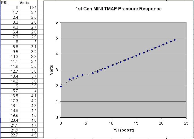
Here are my results (atmospheric here is about 14.5psi - so results will vary slightly at different altitudes):
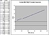
Results are pretty linear - the "fit" line is pretty darn close to the data points. It's likely that my ability to measure pressure accurately was compromised at the pressure levels below about 5psi... so you'd probably get accurate results just by interpolating the line straight through the upper set of values and down through the "0" point.
This seems to exactly match the characteristic curve of the 250kPa Bosch MAP sensor on the first page of this spec sheet.
http://www.bosch.com.au/content/lang...cification.pdf
This might be useful for other applications such as digital gauge installs.
Hope someone finds this useful!
I'm installing a water/meth injection system that reads the voltage off the TMAP sensor signal wire (the yellow/purple one, nearest the right/passenger side of the car). To be able to configure my system for proper control, I needed to understand the output of the TMAP sensor within the boost range. I couldn't find anyone else who had documented this, so I did it!
I just measured from 0 psi atmospheric to max, didn't bother to map the vacuum end of the scale because that isn't relevant to what I'm doing, and I didn't have a good way to generate vacuum nor an accurate way to measure it.
With the TMAP plugged into the wiring harness but removed from the intake manifold, I attached a hose to the sensor plug, and plumbed this to a 5gal air tank with about 25psi in it to start. Switched the ignition to "run" but didn't start the car, so it fed the sensor 5v just like it would normally. I also attached my very accurate digital pressure gauge to the tank. I tapped the TMAP output wire and hooked that up to my voltmeter. I bled down the tank until the voltage started to drop (from 4.95v max voltage). Then I bled down while watching the voltmeter, in increments of 0.1v, stopping to allow the pressure to stabilize and recording the pressure at each voltage level.
Here are my results (atmospheric here is about 14.5psi - so results will vary slightly at different altitudes):
Results are pretty linear - the "fit" line is pretty darn close to the data points. It's likely that my ability to measure pressure accurately was compromised at the pressure levels below about 5psi... so you'd probably get accurate results just by interpolating the line straight through the upper set of values and down through the "0" point.
This seems to exactly match the characteristic curve of the 250kPa Bosch MAP sensor on the first page of this spec sheet.
http://www.bosch.com.au/content/lang...cification.pdf
This might be useful for other applications such as digital gauge installs.
Hope someone finds this useful!
Last edited by BlimeyCabrio; Nov 23, 2009 at 11:40 AM.


Neutral
Joined: Nov 2009
Posts: 1
Likes: 0
This is a great help. The only problem I have is that mine seems to work in reverse i.e. the more boost = the lower the voltage? I have a 2003 Cooper S heavily modified and running under a Motec M800 ECU. I do not use the MAP sensor at all for controlling the engine (done with full Lambda control) but would like to data log the MAP sensor so that I can assess when the supercharger needs refurbishment.
This is something I will have to investigate further as the installer might have used a bridge network.
This is something I will have to investigate further as the installer might have used a bridge network.

Thread
Thread Starter
Forum
Replies
Last Post
Alpha Motoring
MINI Parts for Sale
4
Sep 7, 2020 07:34 PM
gnhovis
MINI Parts for Sale
2
Sep 28, 2015 04:07 AM