
Drivetrain My build. Teaser photos and updates


Thread Starter
|
5th Gear
Joined: Aug 2008
Posts: 1,100
Likes: 13
From: Inman, SC
GOOD NEEEWS EVERYBODY! There is a new Dacia Sandero!
Oh I'm only kidding, but I do have more intercooler goodies!
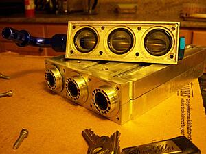
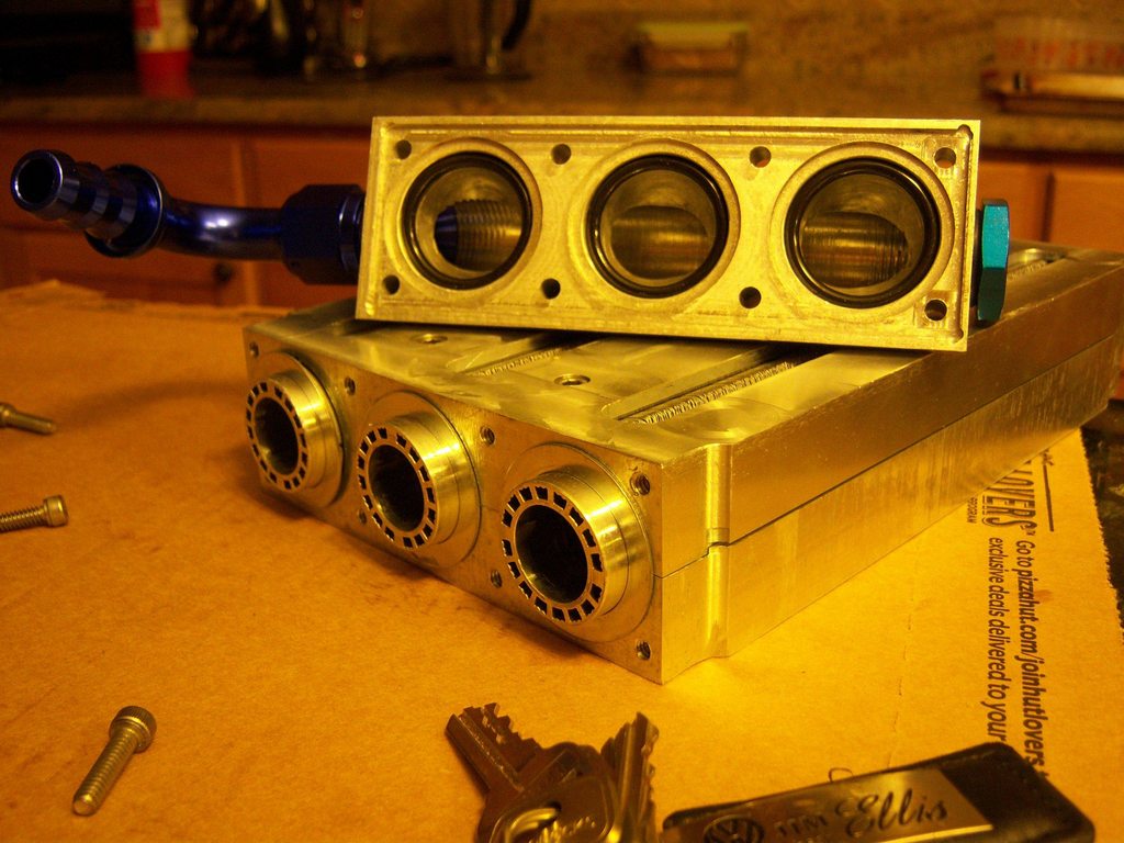
Drilled the core holders for the end-cap bolts. Ended up clamping the whole thing together 6 ways from sunday and then aligning he side of the block vertically with the mill head. Took the clearance bit I used to drill the holes in the feed block and adjusted the mill until the bit would run through the hole bore smoothly with the machine off. Then I locked the machine down, put in a center drill, got a pilot, switched out to a 70% thread for 10-24 screw and drilled a hole 1" deep. I did this for all 8 bolt holes, then using aluminum cutting fluid used a start and bottom tap to tap the holes.
whew. also exploded a 1/8" x 3" solid tungsten carbide end mill that I just bought...
Also done today
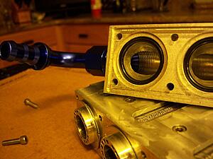
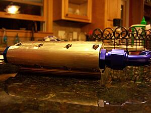
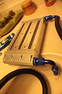
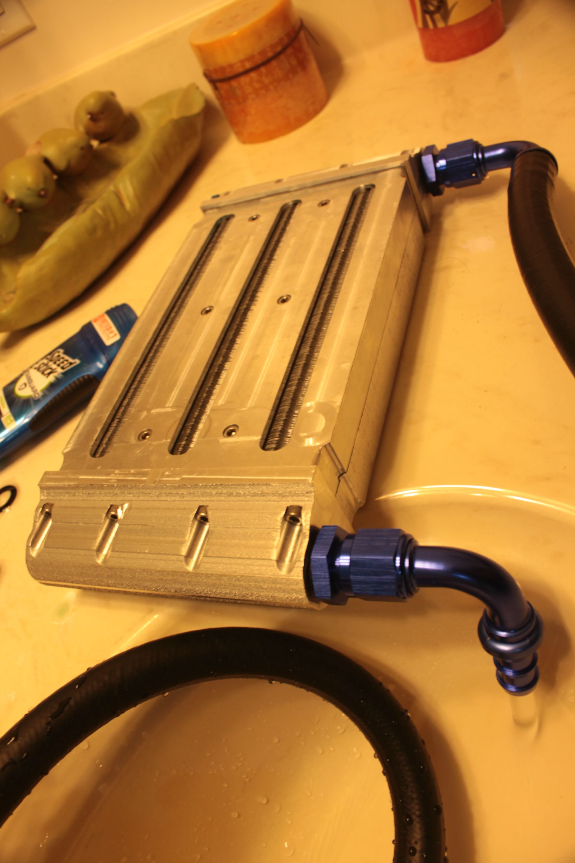
tapped both ends of the water feed block for 7/8-14 thread and put on the -10AN fittings.
Also also done today:
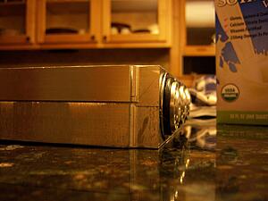
the last end tank is being made currently! should be ready to come out of the mill tomorrow evening, and then I will have to do a few hours of finishing work.
but then the core will be done! (still have to make the air inlets and outlets!
but now, to thank you all for reading,
ITS PICTURE TIME!
daaa duh duh duh. deeee deeee.. can't touch this
Apologies though, the DSLR is out on loan, so I am using a 6 year old kodac easy shot to produce this viewing pleasure. (I miss my big camera )
)

Oh I'm only kidding, but I do have more intercooler goodies!
Drilled the core holders for the end-cap bolts. Ended up clamping the whole thing together 6 ways from sunday and then aligning he side of the block vertically with the mill head. Took the clearance bit I used to drill the holes in the feed block and adjusted the mill until the bit would run through the hole bore smoothly with the machine off. Then I locked the machine down, put in a center drill, got a pilot, switched out to a 70% thread for 10-24 screw and drilled a hole 1" deep. I did this for all 8 bolt holes, then using aluminum cutting fluid used a start and bottom tap to tap the holes.
whew.
also exploded a 1/8" x 3" solid tungsten carbide end mill that I just bought... Also done today
tapped both ends of the water feed block for 7/8-14 thread and put on the -10AN fittings.
Also also done today:
the last end tank is being made currently! should be ready to come out of the mill tomorrow evening, and then I will have to do a few hours of finishing work.
but then the core will be done!
(still have to make the air inlets and outlets!but now, to thank you all for reading,
ITS PICTURE TIME!
daaa duh duh duh. deeee deeee.. can't touch this
Apologies though, the DSLR is out on loan, so I am using a 6 year old kodac easy shot to produce this viewing pleasure. (I miss my big camera
)


Thread Starter
|
5th Gear
Joined: Aug 2008
Posts: 1,100
Likes: 13
From: Inman, SC
air flows fine through the fins. Solidworks can due fluid dynamic simulations if you have the correct plugin. We dont have it on ours due to I work for a company that mainly uses SW to design blown film dies, and resin melt doesn't follow the flow parameters SW handles well  slighly non-newtonian.
but the cores them selves are made by opcon on an EDM. They are a proven technology, but tend to be found only in high-end applications as they are expensive. The cores are ~$200 each, and then you have to custom machine the "core" like I have as everything is a non-standard size.
The cores are spec'd at 39.5mm +- .1mm, and with thermal expansion the carrier diameter is spec'd from opcon to need to be 39.6mm to 39.8mm in diameter. And no that is not a standard equivalent.
but sort of a background FYI, an engine makes torque, the rate of which is horsepower. The rate of torque... aka horsepower... can be correlated to how much air is being consumed by your motor...
la de da, math math math.
These cores are rated at 0.5psi pressure drop @ 1hp/2.5mm core length. each of these are 245mm long (231 for the fins, and thats what counts)
so 231*3/2.5 = ~270 hp with only a .5psi pressure drop across the core. (which is pretty freakin fantastic!)
Obviously it will flow more with a higher pressure drop.
Key comes from the fact that most intercoolers run the other way. Air takes the long and narrow path, instead of this way in which the air is spread out and takes a shorter path with a lot more surface contact.
slighly non-newtonian.but the cores them selves are made by opcon on an EDM. They are a proven technology, but tend to be found only in high-end applications as they are expensive. The cores are ~$200 each, and then you have to custom machine the "core" like I have as everything is a non-standard size.
The cores are spec'd at 39.5mm +- .1mm, and with thermal expansion the carrier diameter is spec'd from opcon to need to be 39.6mm to 39.8mm in diameter. And no that is not a standard equivalent.
but sort of a background FYI, an engine makes torque, the rate of which is horsepower. The rate of torque... aka horsepower... can be correlated to how much air is being consumed by your motor...
la de da, math math math.
These cores are rated at 0.5psi pressure drop @ 1hp/2.5mm core length. each of these are 245mm long (231 for the fins, and thats what counts)
so 231*3/2.5 = ~270 hp with only a .5psi pressure drop across the core. (which is pretty freakin fantastic!)
Obviously it will flow more with a higher pressure drop.
Key comes from the fact that most intercoolers run the other way. Air takes the long and narrow path, instead of this way in which the air is spread out and takes a shorter path with a lot more surface contact.
Thread Starter
|
5th Gear
Joined: Aug 2008
Posts: 1,100
Likes: 13
From: Inman, SC
okay, time for some genuine bmw parts! woohoo! thanks to ECS tuning, parts I have always wanted are now affordable, and readily available. So,
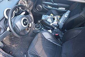
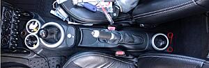
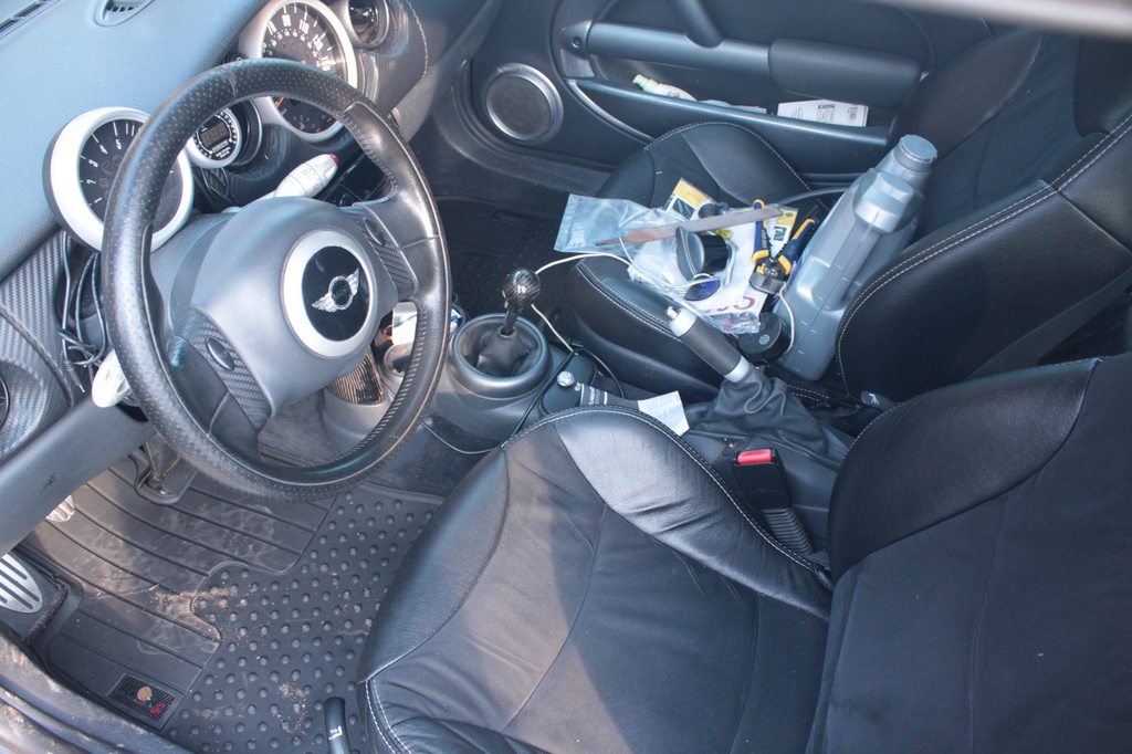
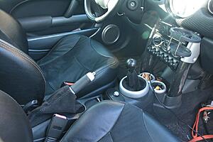
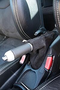
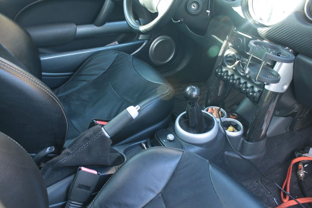
new e-brake console (face lift) and changed out to silver trim rings. the new shift and e-brake boot are still in the mail, but will be here shortly (alcantara with contrast double stitching in bmw M-style 5 but in 3 shades of silver/grey)
apologies for the mess
before!
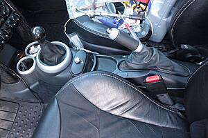
and After!
install notes on e-brake console:
IT DOES NOT "drop in" TO THE PRE-FACELIFT MODEL!
but it does with a little convincing
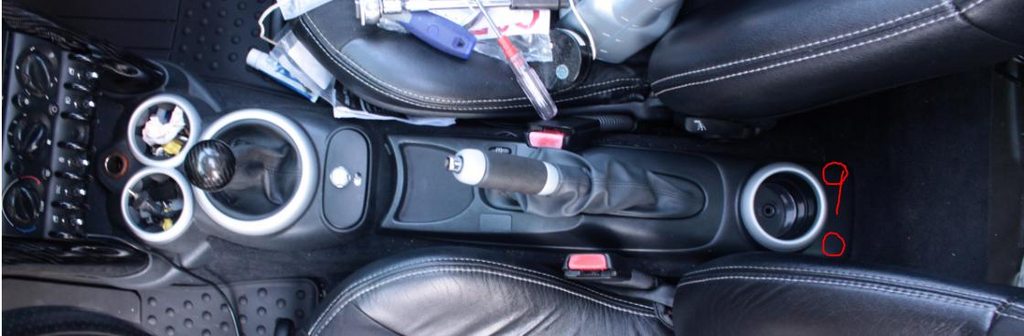
Quite simple. If you take the pre-facelift one out, flip it over, and look at where the "clip" tabs are, you will immediately notice that the ones at the back of the console are ~1" closer to the firewall on the updated version. All I did was measure the hole in the e-brake console base and drill 2 new holes ~1 " cl in front of the old ones. then the new console clicked right into place!
reference: red circles are approximate location of where I had to drill holes in the base.
ON TO THE ENGINE BAY!!!
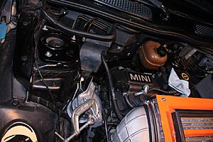
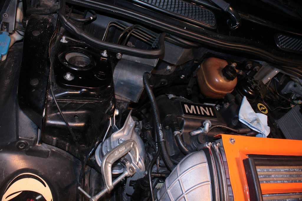
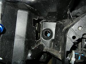
decided I need every ounce of room there is available, and after seeing a facelift engine bay the other week I realized (don't know why I hadn't sooner, no reason too I guess) that the facelifts lack a clunk of metal on the upper motor mount. So I switched!
before A:
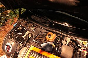
before b :
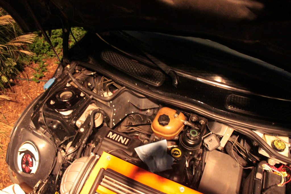
after a:
after b:
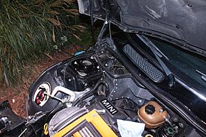
as you can see I made enough room to put a catch can, power steering reservoir, or custom coolant reservoir where the motor mount used to be.
the c-clamp you ask? umm... I made a booboo...
 JB weld is currently fixing it until my new miller tig welder gets here this/next week. (Diversion 180 TIG with pyrex short cups and a miller digital elite helmet for the welding-inclined. )
new e-brake console (face lift) and changed out to silver trim rings. the new shift and e-brake boot are still in the mail, but will be here shortly (alcantara with contrast double stitching in bmw M-style 5 but in 3 shades of silver/grey)
apologies for the mess
before!
and After!

install notes on e-brake console:
IT DOES NOT "drop in" TO THE PRE-FACELIFT MODEL!
but it does with a little convincing
Quite simple. If you take the pre-facelift one out, flip it over, and look at where the "clip" tabs are, you will immediately notice that the ones at the back of the console are ~1" closer to the firewall on the updated version. All I did was measure the hole in the e-brake console base and drill 2 new holes ~1 " cl in front of the old ones. then the new console clicked right into place!
reference: red circles are approximate location of where I had to drill holes in the base.
ON TO THE ENGINE BAY!!!
decided I need every ounce of room there is available, and after seeing a facelift engine bay the other week I realized (don't know why I hadn't sooner, no reason too I guess) that the facelifts lack a clunk of metal on the upper motor mount. So I switched!
before A:
before b :

after a:
after b:

as you can see I made enough room to put a catch can, power steering reservoir, or custom coolant reservoir where the motor mount used to be.
the c-clamp you ask?
umm... I made a booboo... JB weld is currently fixing it until my new miller tig welder gets here this/next week. (Diversion 180 TIG with pyrex short cups and a miller digital elite helmet for the welding-inclined. )


 It happened to me too lol
Thread Starter
|
5th Gear
Joined: Aug 2008
Posts: 1,100
Likes: 13
From: Inman, SC
yup. The pre-facelift ones "grooves" for the nut on the backside are just a hair shallower than the nut depth (which is a flared nut). I didn't notice that the post-facelift channels were ~4mm deeper than the nut, so when I was only ~ 4 lf-lbs, the nut wedged the aluminum apart and cracked the casting. JB weld fixed it nicely for now though. Welder is here tomorrow!!! woohoo!
Been about 2 years since I've done any welding, and 3 since I have touched aluminum, so I will be doing a lot of practice beads before it touches the car though!
Been about 2 years since I've done any welding, and 3 since I have touched aluminum, so I will be doing a lot of practice beads before it touches the car though!


okay, time for some genuine bmw parts! woohoo! thanks to ECS tuning, parts I have always wanted are now affordable, and readily available. So,
new e-brake console (face lift) and changed out to silver trim rings. the new shift and e-brake boot are still in the mail, but will be here shortly (alcantara with contrast double stitching in bmw M-style 5 but in 3 shades of silver/grey)
apologies for the mess
before!

and After!

install notes on e-brake console:
IT DOES NOT "drop in" TO THE PRE-FACELIFT MODEL!
but it does with a little convincing
Quite simple. If you take the pre-facelift one out, flip it over, and look at where the "clip" tabs are, you will immediately notice that the ones at the back of the console are ~1" closer to the firewall on the updated version. All I did was measure the hole in the e-brake console base and drill 2 new holes ~1 " cl in front of the old ones. then the new console clicked right into place!
reference: red circles are approximate location of where I had to drill holes in the base.

ON TO THE ENGINE BAY!!!
decided I need every ounce of room there is available, and after seeing a facelift engine bay the other week I realized (don't know why I hadn't sooner, no reason too I guess) that the facelifts lack a clunk of metal on the upper motor mount. So I switched!
before A:

before b :

after a:

after b:

as you can see I made enough room to put a catch can, power steering reservoir, or custom coolant reservoir where the motor mount used to be.
the c-clamp you ask? umm... I made a booboo... JB weld is currently fixing it until my new miller tig welder gets here this/next week. (Diversion 180 TIG with pyrex short cups and a miller digital elite helmet for the welding-inclined. )
new e-brake console (face lift) and changed out to silver trim rings. the new shift and e-brake boot are still in the mail, but will be here shortly (alcantara with contrast double stitching in bmw M-style 5 but in 3 shades of silver/grey)
apologies for the mess
before!
and After!
install notes on e-brake console:
IT DOES NOT "drop in" TO THE PRE-FACELIFT MODEL!
but it does with a little convincing
Quite simple. If you take the pre-facelift one out, flip it over, and look at where the "clip" tabs are, you will immediately notice that the ones at the back of the console are ~1" closer to the firewall on the updated version. All I did was measure the hole in the e-brake console base and drill 2 new holes ~1 " cl in front of the old ones. then the new console clicked right into place!
reference: red circles are approximate location of where I had to drill holes in the base.
ON TO THE ENGINE BAY!!!
decided I need every ounce of room there is available, and after seeing a facelift engine bay the other week I realized (don't know why I hadn't sooner, no reason too I guess) that the facelifts lack a clunk of metal on the upper motor mount. So I switched!
before A:
before b :
after a:
after b:
as you can see I made enough room to put a catch can, power steering reservoir, or custom coolant reservoir where the motor mount used to be.
the c-clamp you ask?
umm... I made a booboo... JB weld is currently fixing it until my new miller tig welder gets here this/next week. (Diversion 180 TIG with pyrex short cups and a miller digital elite helmet for the welding-inclined. )You are welcome, looks good with the update.
__________________

MINI Guru/ MINI Owner Since 2004 | NEW Lifetime Part Replacement | Local Pickup
Milltek | Genuine MINI | Forge Motorsport | NM Engineering | ECS Performance | M7 Speed
Customer Service Hours: 8am-8pm EST|Sales Team Hours: 8am-11pm | SAT 10am-7pm 800.924.5172
MINI Guru/ MINI Owner Since 2004 | NEW Lifetime Part Replacement | Local Pickup
Milltek | Genuine MINI | Forge Motorsport | NM Engineering | ECS Performance | M7 Speed
Customer Service Hours: 8am-8pm EST|Sales Team Hours: 8am-11pm | SAT 10am-7pm 800.924.5172
Thread Starter
|
5th Gear
Joined: Aug 2008
Posts: 1,100
Likes: 13
From: Inman, SC
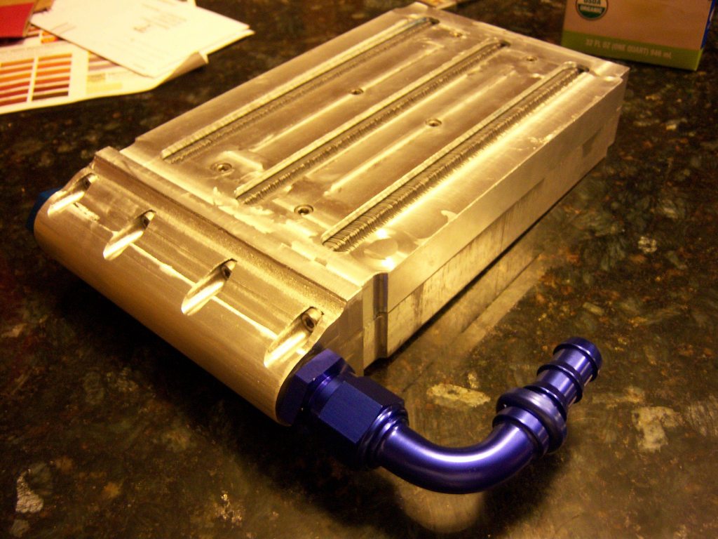
Core is finished!
No leaks noticed either!
Now just to make the end tanks....
Curently weighing options of
1. CNC foam negative mould, gel coat and carbon fiber
2. Make it out of Milliken Tegris (would require CNC aluminum mould, and working with a third party pressure thermoformer,
or
3. make it out of good ole fashioned aluminum all nicely tig welded together.(is probably what will happen, but hey, a guy can dream...)
I do have the foam and the vacuum bagging equipt for composite layup though... haha
Thread Starter
|
5th Gear
Joined: Aug 2008
Posts: 1,100
Likes: 13
From: Inman, SC
well we have a hobby mill CNC at work, so the hours on that are "free" .
The materials were not that expensive surprisingly.
2 blocks of 1" x 8" x 12" 6061 aluminum were $69 ($34.50 for each of the core "sides")
the 2 end blocks were ~$17 a pop for 2"x3"x8" stock.
I used metal express (located in charolette, NC). They have a supply shop in Duncan, SC (where my work is) and they have the best prices for raw stock by far of anywhere we know of at work!
The laminova cores themselves are normally $200/per , but I picked them up off ebay from a company that had overstocked for $55/per
I spent ~ 4 hours in solidworks designing. (the laminova core manufacturers have dimensional specs for the o-ring seats etc. so it was not too difficult)
And probably about 1 hour of setup for each part and 3 hours of cleanup/drilling and tapping.
I also spent ~ 2 hours on each of the end blocks to drill the main bore that is tapped for the fittings. (8" is a deep drill)
total CNC time is not quite relevant as this is a hobby CNC and cannot hog large sections out like a HAAS industrial CNC could, but it is in the neighborhood of ~180 hours of cut time. It would be a fraction of that on a mill in a machine shop.
but for me, my personal time was play as I enjoy making things and working with metal, so out-the-door cost for me is
$268 !
but my former economics professor would chastise me for saying that was the total cost! haha
Oh, and damn aluminum AN fittings and hose were another $70 ish I think... It's 15' of hose though.... Got all of those supplies from Jegs.com, and they were the "jegs" branded items.
The materials were not that expensive surprisingly.
2 blocks of 1" x 8" x 12" 6061 aluminum were $69 ($34.50 for each of the core "sides")
the 2 end blocks were ~$17 a pop for 2"x3"x8" stock.
I used metal express (located in charolette, NC). They have a supply shop in Duncan, SC (where my work is) and they have the best prices for raw stock by far of anywhere we know of at work!
The laminova cores themselves are normally $200/per
, but I picked them up off ebay from a company that had overstocked for $55/perI spent ~ 4 hours in solidworks designing. (the laminova core manufacturers have dimensional specs for the o-ring seats etc. so it was not too difficult)
And probably about 1 hour of setup for each part and 3 hours of cleanup/drilling and tapping.
I also spent ~ 2 hours on each of the end blocks to drill the main bore that is tapped for the fittings. (8" is a deep drill)
total CNC time is not quite relevant as this is a hobby CNC and cannot hog large sections out like a HAAS industrial CNC could, but it is in the neighborhood of ~180 hours of cut time. It would be a fraction of that on a mill in a machine shop.
but for me, my personal time was play as I enjoy making things and working with metal, so out-the-door cost for me is
$268 !
but my former economics professor would chastise me for saying that was the total cost! haha
Oh, and damn aluminum AN fittings and hose were another $70 ish I think... It's 15' of hose though.... Got all of those supplies from Jegs.com, and they were the "jegs" branded items.
Thread Starter
|
5th Gear
Joined: Aug 2008
Posts: 1,100
Likes: 13
From: Inman, SC
not drivetrain related, but
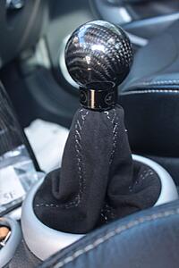
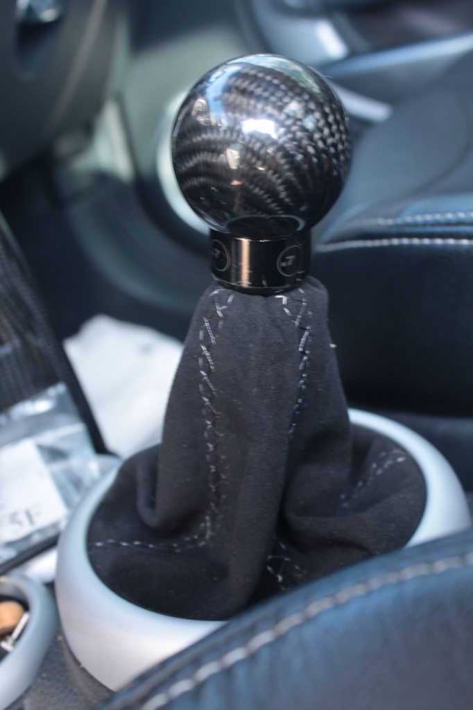
new shift and e-brake boot!
black alcantara with "M" style 5 sitching and 4 panel layout from redlinegoods.com. Changed the color scheme up on the stitching though to go with my katzkin seats.
Now everything matches :3
new shift and e-brake boot!
black alcantara with "M" style 5 sitching and 4 panel layout from redlinegoods.com. Changed the color scheme up on the stitching though to go with my katzkin seats.
Now everything matches :3


Thread Starter
|
5th Gear
Joined: Aug 2008
Posts: 1,100
Likes: 13
From: Inman, SC
well I have some pictures and updates that are related! but non mini specific.
I am an engineer by education and trade (young, 22yo), but enjoy metal work.
It's been ~ 1.5 years since I've done any real welding (made my exhaust on the mini from the header back) but it was stainless.
For this build to move forward I realized a lot of welding would need to be done, so I put a few other things build related on a immediate purchase hold (directly... turbo, TPR2R-T head etc. They will be had once liquid funds are available again!) and bought a
Miller Diversion 180 tig,
a quality welding helmet - I value my eyesight, and the one I got (miller digital elite) came with a heafty price tag, but it is worth every penny! so easy to see out of this one!
2% lanthnated electrodes (for stainless) and pure tungsten (for aluminum)
a 160 cu ft tank of 100% argon (refils only cost ~$30 through our supplier at work)
and pulled a good bit of aluminum scrap from the bin from the support material from my CNC work (it is all good grade 6061 T6)
So the past week has just been practice beads. Want to be 100% confident before I lite the torch on anything car related. That could get real expensive real quick.
Been doing 1/2", 1/4", 1/8" and thin stuff down to .065" sheet. It is not a pulse machine, so coke cans are not possible.
I can post pictures of the new welding setup if anybody wants, but for now I will just attach these here.
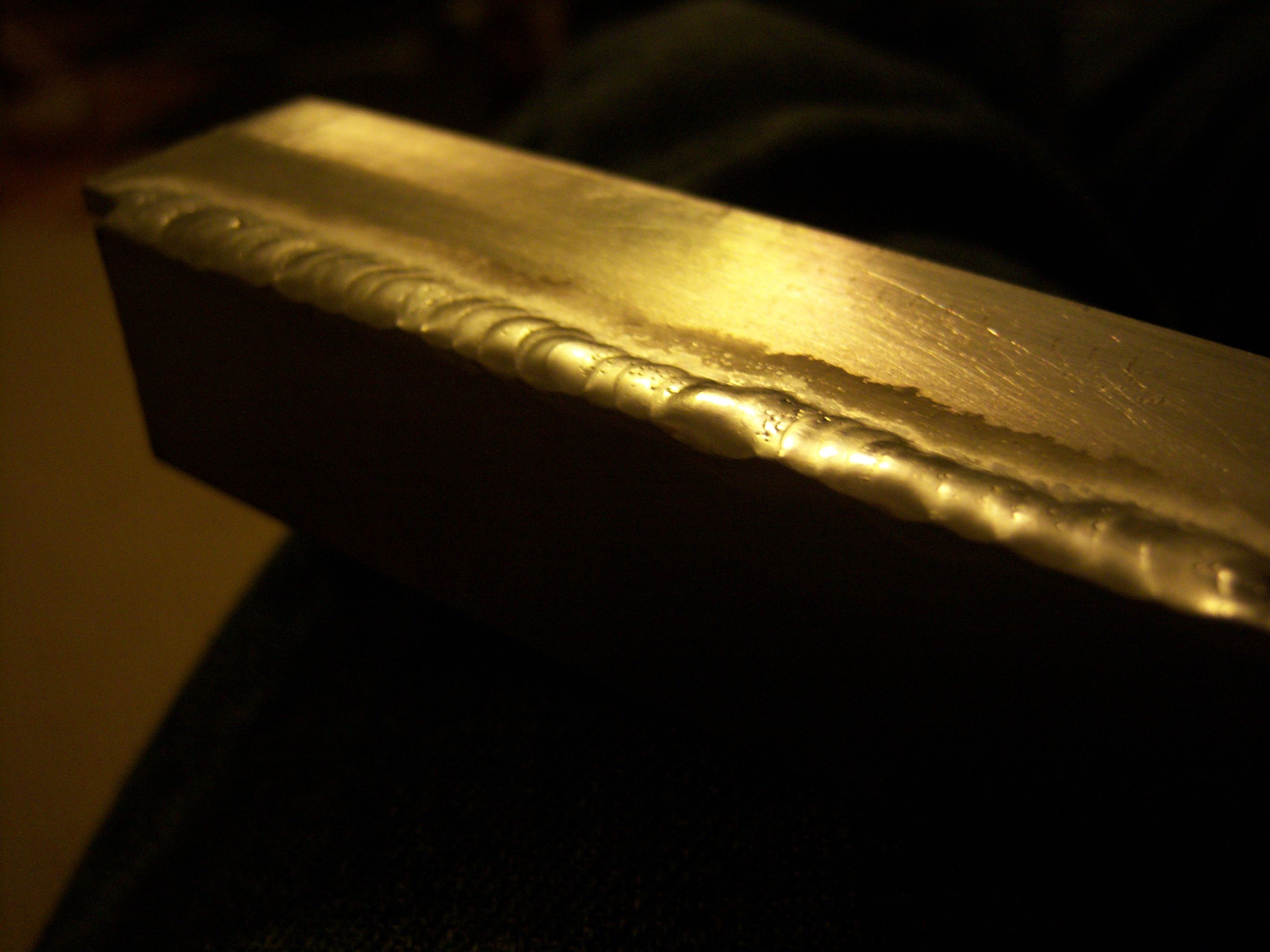
These are images of my 5th and 6th passes EVER on aluminum (never attempted it before). not the prettiest, and need to work on speed consistency, but pretty good!.
I have gotten progressively better as I have gone as well.
This one was a little fast and not quite enough filler
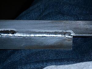
this was a better speed and better filler ammount, but not as consistent.

Both welds in reality would be perfectly fine for my applications, but I still mess up every now and then and touch the filler to the electrode on long passes where I am having to feed the filler through my fingers. want to "fix" this before I try on the car.
I am an engineer by education and trade (young, 22yo), but enjoy metal work.
It's been ~ 1.5 years since I've done any real welding (made my exhaust on the mini from the header back) but it was stainless.
For this build to move forward I realized a lot of welding would need to be done, so I put a few other things build related on a immediate purchase hold (directly... turbo, TPR2R-T head etc. They will be had once liquid funds are available again!) and bought a
Miller Diversion 180 tig,
a quality welding helmet - I value my eyesight, and the one I got (miller digital elite) came with a heafty price tag, but it is worth every penny! so easy to see out of this one!
2% lanthnated electrodes (for stainless) and pure tungsten (for aluminum)
a 160 cu ft tank of 100% argon (refils only cost ~$30 through our supplier at work)
and pulled a good bit of aluminum scrap from the bin from the support material from my CNC work (it is all good grade 6061 T6)
So the past week has just been practice beads. Want to be 100% confident before I lite the torch on anything car related. That could get real expensive real quick.
Been doing 1/2", 1/4", 1/8" and thin stuff down to .065" sheet. It is not a pulse machine, so coke cans are not possible.
I can post pictures of the new welding setup if anybody wants, but for now I will just attach these here.
These are images of my 5th and 6th passes EVER on aluminum (never attempted it before). not the prettiest, and need to work on speed consistency, but pretty good!.
I have gotten progressively better as I have gone as well.
This one was a little fast and not quite enough filler

this was a better speed and better filler ammount, but not as consistent.
Both welds in reality would be perfectly fine for my applications, but I still mess up every now and then and touch the filler to the electrode on long passes where I am having to feed the filler through my fingers. want to "fix" this before I try on the car.
Thread Starter
|
5th Gear
Joined: Aug 2008
Posts: 1,100
Likes: 13
From: Inman, SC
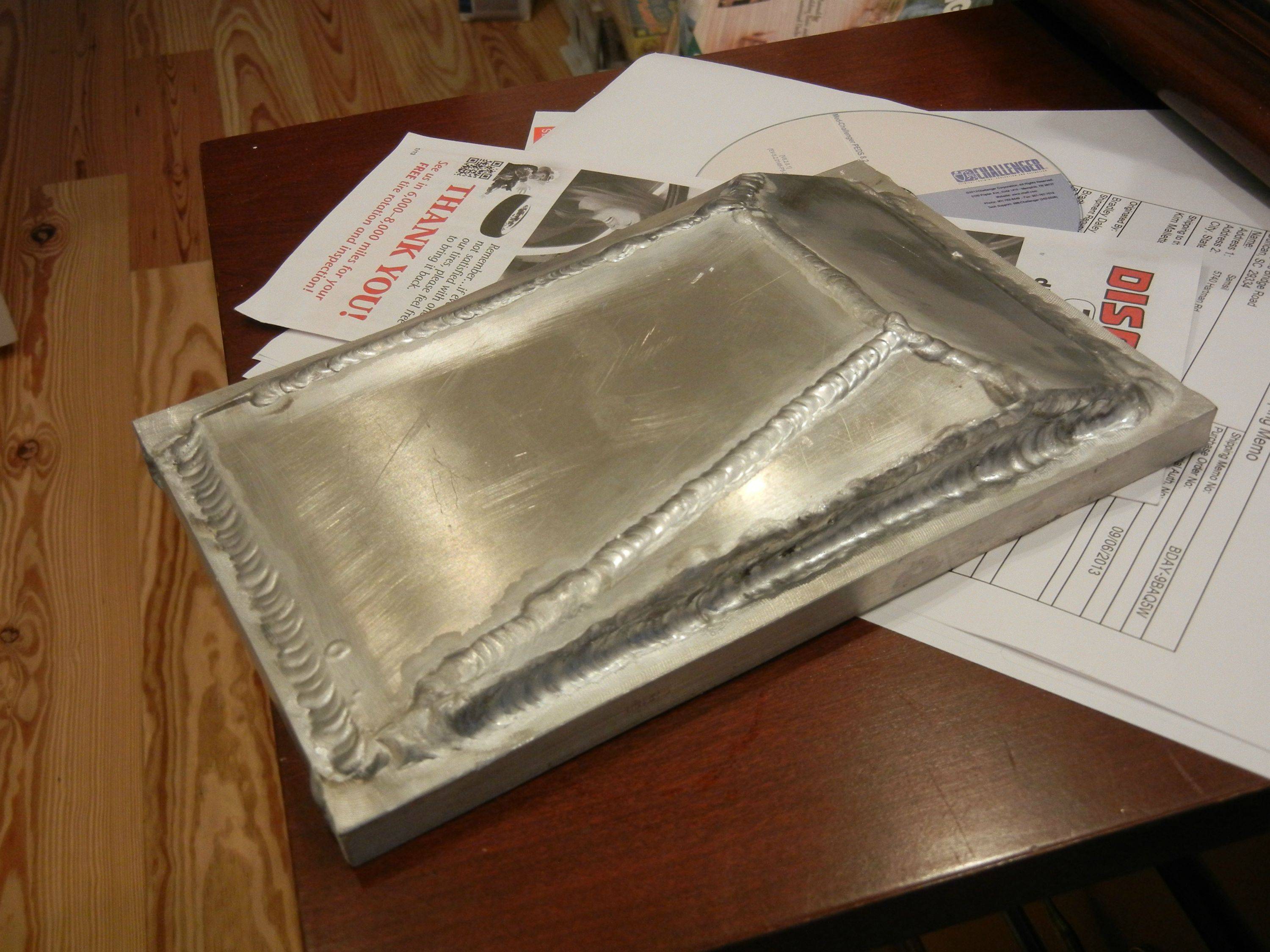
UPDATE! (small one)
First end tank is almost done!
soo.. I'm a just leave dis her.
I am brand new to welding aluminum and only had limited work with steel before, so I think it is pretty good! Welded inside and out.

First end tank is almost done!
soo.. I'm a just leave dis her.
I am brand new to welding aluminum and only had limited work with steel before, so I think it is pretty good! Welded inside and out.


4th Gear
Joined: Jan 2011
Posts: 478
Likes: 1
Having bought them, how do you feel about the katzkin seat covers?
My car was off a dealer lot and the only thing it's really missing are leather seats.
My car was off a dealer lot and the only thing it's really missing are leather seats.
Thread Starter
|
5th Gear
Joined: Aug 2008
Posts: 1,100
Likes: 13
From: Inman, SC
they are fantastic!
note though: the leather they use on the non-contact surfaces (like the bottoms of the rear seats.. by bottoms I mean the bottom of the seat back that never sees the light of day UNLESS you have the seats folded down) seems to be thinner and not as resilient (mine tore slightly) but it is just cosmetic and small.
Seats look great, and I love my suede inserts. Noticeably more grippy that the leatherette seats that were factory!
Thread Starter
|
5th Gear
Joined: Aug 2008
Posts: 1,100
Likes: 13
From: Inman, SC
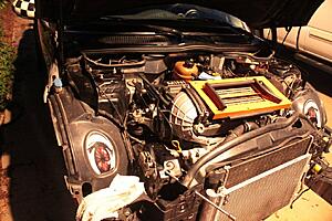
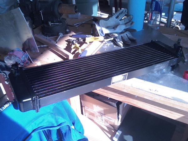
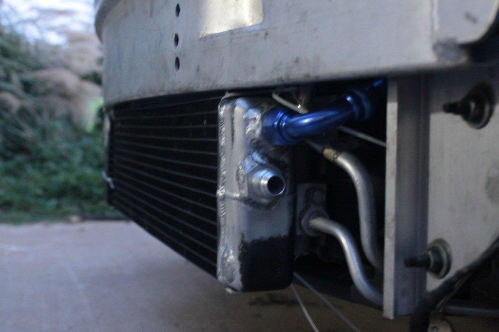
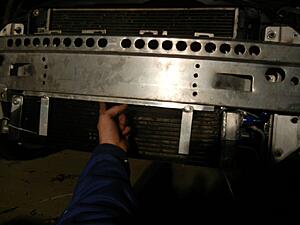
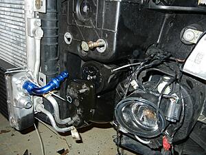
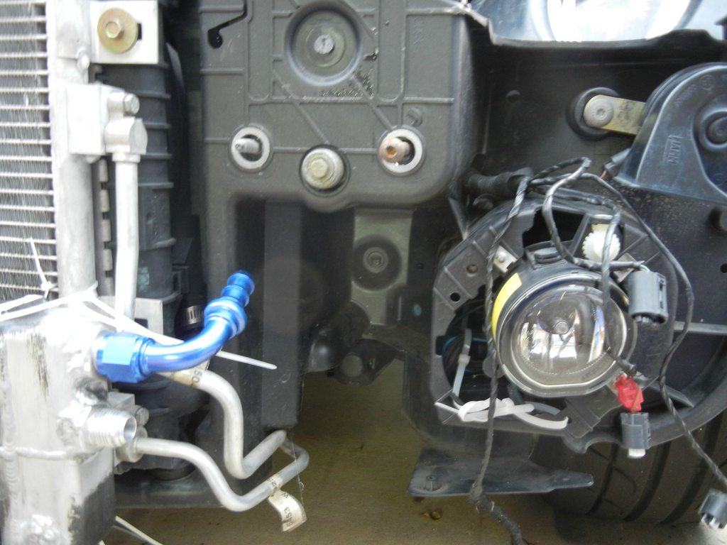
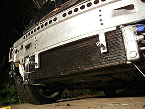
new heat exchanger is here! (this thing fits in the front lower bumper with a slight modification to the edges of the lower grill.. barely  ... while retaining my A/C! )
Garrett intercooler water exchanger. OEM for an '04 SVT cobra
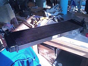
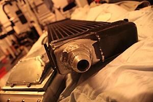
old fittings chopped off, welded over, and new AN fittings!
Two -10AN inlets (one for each of the two exchangers) and a -12AN outlet to the water pump (should be here next week)
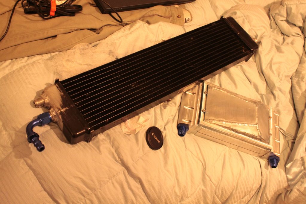
-10 AN inlets
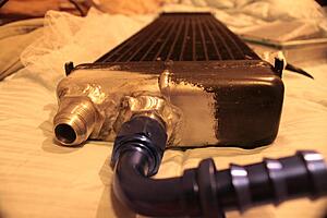
-12 AN outlet
Enjoy!
... while retaining my A/C! )Garrett intercooler water exchanger. OEM for an '04 SVT cobra
old fittings chopped off, welded over, and new AN fittings!
Two -10AN inlets (one for each of the two exchangers) and a -12AN outlet to the water pump (should be here next week)
-10 AN inlets

-12 AN outlet

Enjoy!
Thread Starter
|
5th Gear
Joined: Aug 2008
Posts: 1,100
Likes: 13
From: Inman, SC
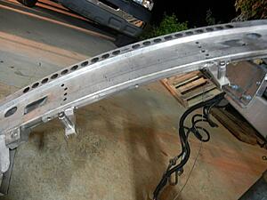
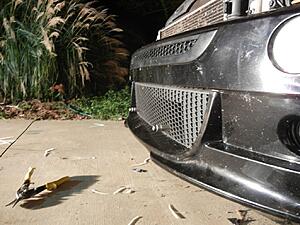
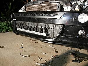
Note: I had to modify the bumper (cut ~3/8" out of the lower outer corners in the grill area) and heated and re-formed the lower grill in order to make this radiator fit.
Details (read: pictures and descriptions) can be found on imgur here!
http://imgur.com/a/p5aXf
teaser photo though
Details (read: pictures and descriptions) can be found on imgur here!
http://imgur.com/a/p5aXf
teaser photo though
Thread Starter
|
5th Gear
Joined: Aug 2008
Posts: 1,100
Likes: 13
From: Inman, SC
well stay tuned BSTINS!
The bosch water pump for the charge cooling system should be here tuesday as well as the metal for making new brackets for the light bar!
Had an alta light bar before, but those brackets bolted to the inside of the bumper.
Will be drilling holes in the underside of the bumper, inserting riv nuts, and using 1"x0.25" x .125" aluminum channel, some solid aluminum rod and some .5"x.5" square stock to make a new bracket to hold the light bar!
Thread Starter
|
5th Gear
Joined: Aug 2008
Posts: 1,100
Likes: 13
From: Inman, SC
okay, so today I went by my favorite store in the area (metal supply place) and picked up various shapes of 6061 T6 plate, bar, rod, and channel stock and started to work on making a new light bar bracket as the alta one will no longer fit with the heat exchanger in the way.
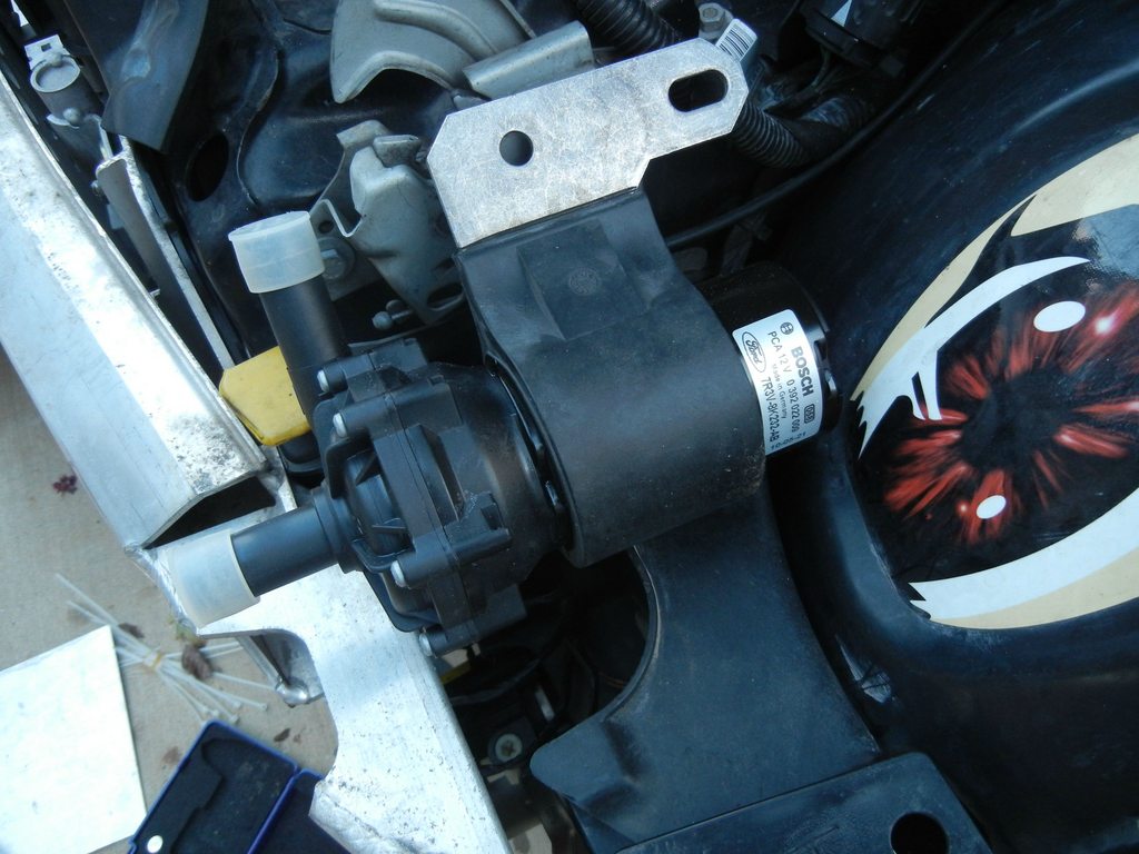
I also fit the new bosch water pump that came in today behind the drivers side crush tube in a nifty little cavity. Took some convincing, but it is there to stay!
As usual, full write up and all images are in an album on imgur, but I will post a few highlighs here
for the full writeup go here -> http://imgur.com/a/OAkn3
in summary
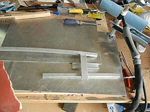
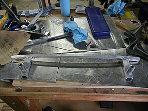
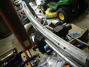
bent 1/2" square stock to bumper profile. This will mount to underside of bumper using rivnut inserts into the bumper, and M6 bolts.
Using 1"x.5"x.125" channel for the "drops" as they are rigid in both directions.
here is one side "jigged" up before welding
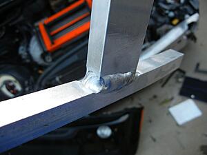
and after welding
where it is going
and onto the water pump!
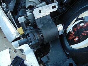
decided to see if it would fit here behind the drivers side crush tube.

took a little... convincing
but she fits like a glove! a little too well. had to cut a small relief into the bumper itself to that the connector could attach
That is all for today!!

I also fit the new bosch water pump that came in today behind the drivers side crush tube in a nifty little cavity. Took some convincing, but it is there to stay!
As usual, full write up and all images are in an album on imgur, but I will post a few highlighs here
for the full writeup go here -> http://imgur.com/a/OAkn3
in summary
bent 1/2" square stock to bumper profile. This will mount to underside of bumper using rivnut inserts into the bumper, and M6 bolts.
Using 1"x.5"x.125" channel for the "drops" as they are rigid in both directions.
here is one side "jigged" up before welding

and after welding


where it is going

and onto the water pump!
decided to see if it would fit here behind the drivers side crush tube.
took a little... convincing
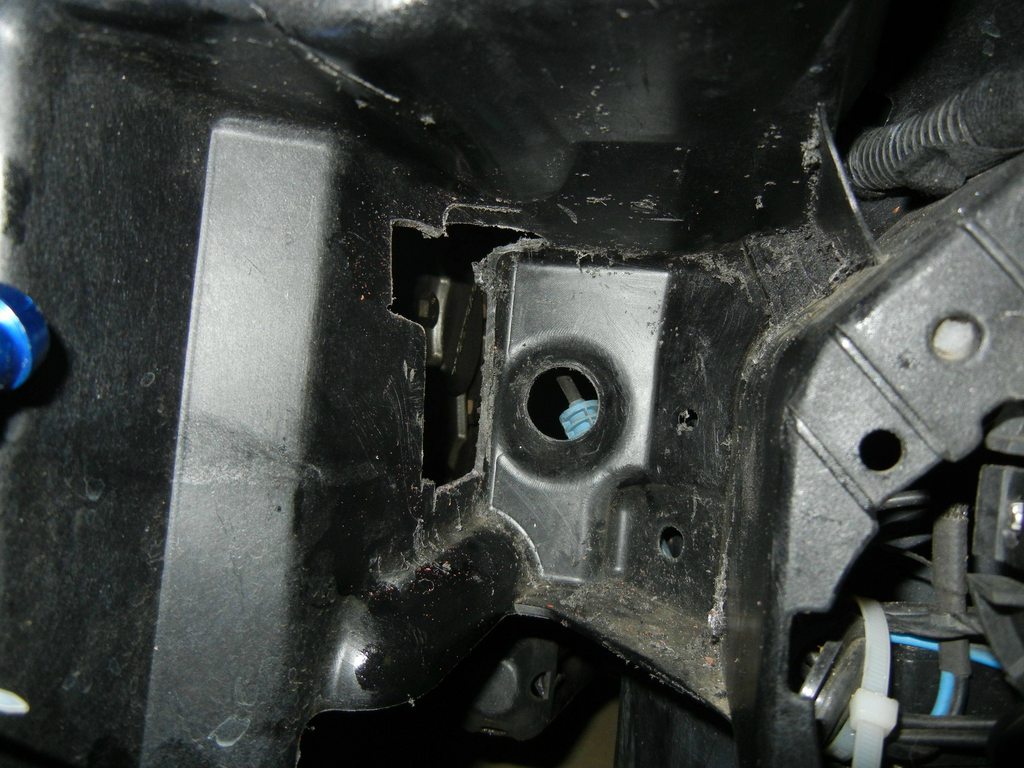
but she fits like a glove! a little too well. had to cut a small relief into the bumper itself to that the connector could attach

That is all for today!!
Thread Starter
|
5th Gear
Joined: Aug 2008
Posts: 1,100
Likes: 13
From: Inman, SC
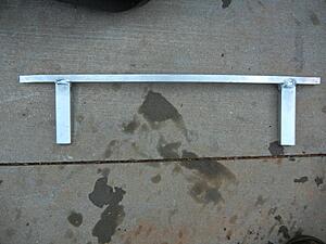
light bar almost finished!
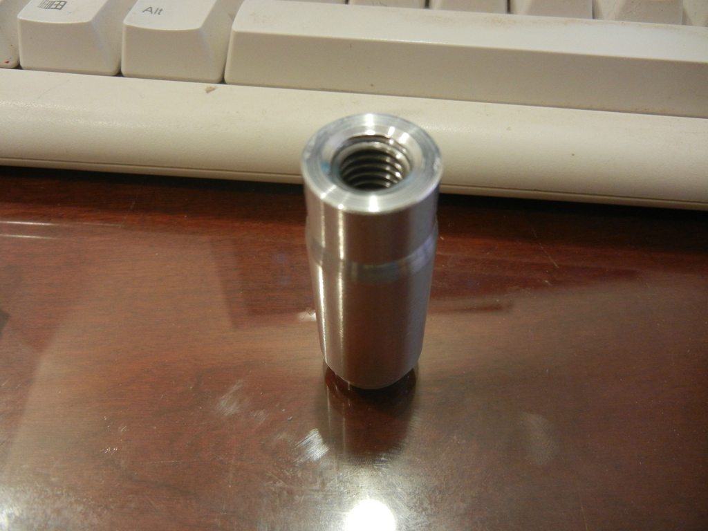
got a bit bored at work today, so I headed out to the shop and decided to try my hand at the lathe.
the machinist showed me a few things yesterday and I played around a little bit, but went out and made these puppies today!
started as 3/4" round stock and they have stainless helicoil inserts
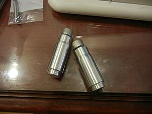
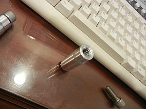

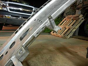
the "notch" at the back is .623" in diameter ( 2 thou under 5/8") so I drilled some 5/8" holes into the light bar drop downs, these sat flush against the front and gave me a nice weld surface at the back! Welded up and cannot see any of it from the front. Clean.
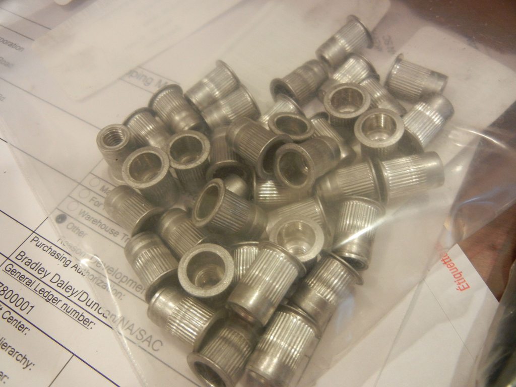
Next, for those of you that have never seen what happens next, these are called rivnuts.
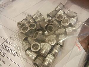
They are not perfect and have flaws, but they essentially allow you (in this case and size) to drill a 10mm hole, thread one of these onto a riv nut tool (looks like a regular rivet gun but it has a retractable bolt sticking out of it)
put it through the hold, squeeze the handle, the "ribbed" section expands against the back of your sheet or plate metal/plastic/composite and leaves you with a aluminum bodied, steel thread M6x1.0 "nut"!
they are great for putting bolts into things normally too thin to drill and tap.
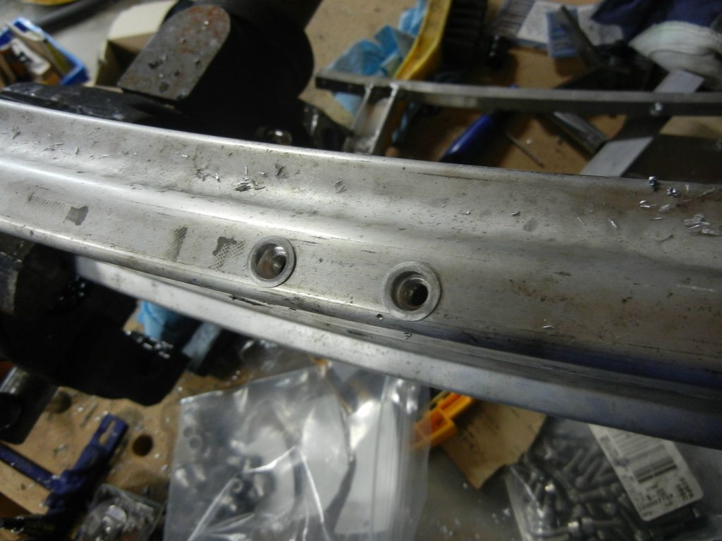
and this is how I used them
Drilled some holes into the light bar bracket (drilled and countersunk for socket head m6 bolts) and then drilled put some riv nuts into the bottom side of the bumper
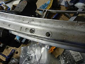
(sorry for the mess, lots going on at this house)
and then the two bolt right up!
And man oh man is this thing stiff.
absolutely 0 flex. picked up the bumper by the "pegs" and shook the bumper and no movement.
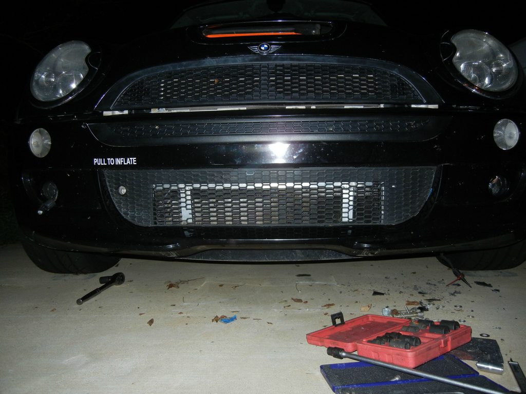
on the car
side view with bumper on
and then I went ahead and cut a 22" piece of the channel (same width as alta bar) and put two more 10mm holes in the front at 16.0625" OC (peg distance)
Still need to decide exactly how I want to mount the lights themselves (horizontal welded bracket or drill and bolt vertical and have no left or right adjustment)
that is all for today!
thoughts?
got a bit bored at work today, so I headed out to the shop and decided to try my hand at the lathe.
the machinist showed me a few things yesterday and I played around a little bit, but went out and made these puppies today!
started as 3/4" round stock and they have stainless helicoil inserts


the "notch" at the back is .623" in diameter ( 2 thou under 5/8") so I drilled some 5/8" holes into the light bar drop downs, these sat flush against the front and gave me a nice weld surface at the back! Welded up and cannot see any of it from the front. Clean.

Next, for those of you that have never seen what happens next, these are called rivnuts.
They are not perfect and have flaws, but they essentially allow you (in this case and size) to drill a 10mm hole, thread one of these onto a riv nut tool (looks like a regular rivet gun but it has a retractable bolt sticking out of it)
put it through the hold, squeeze the handle, the "ribbed" section expands against the back of your sheet or plate metal/plastic/composite and leaves you with a aluminum bodied, steel thread M6x1.0 "nut"!
they are great for putting bolts into things normally too thin to drill and tap.
and this is how I used them
Drilled some holes into the light bar bracket (drilled and countersunk for socket head m6 bolts) and then drilled put some riv nuts into the bottom side of the bumper

(sorry for the mess, lots going on at this house)
and then the two bolt right up!
And man oh man is this thing stiff.
absolutely 0 flex. picked up the bumper by the "pegs" and shook the bumper and no movement.


on the car
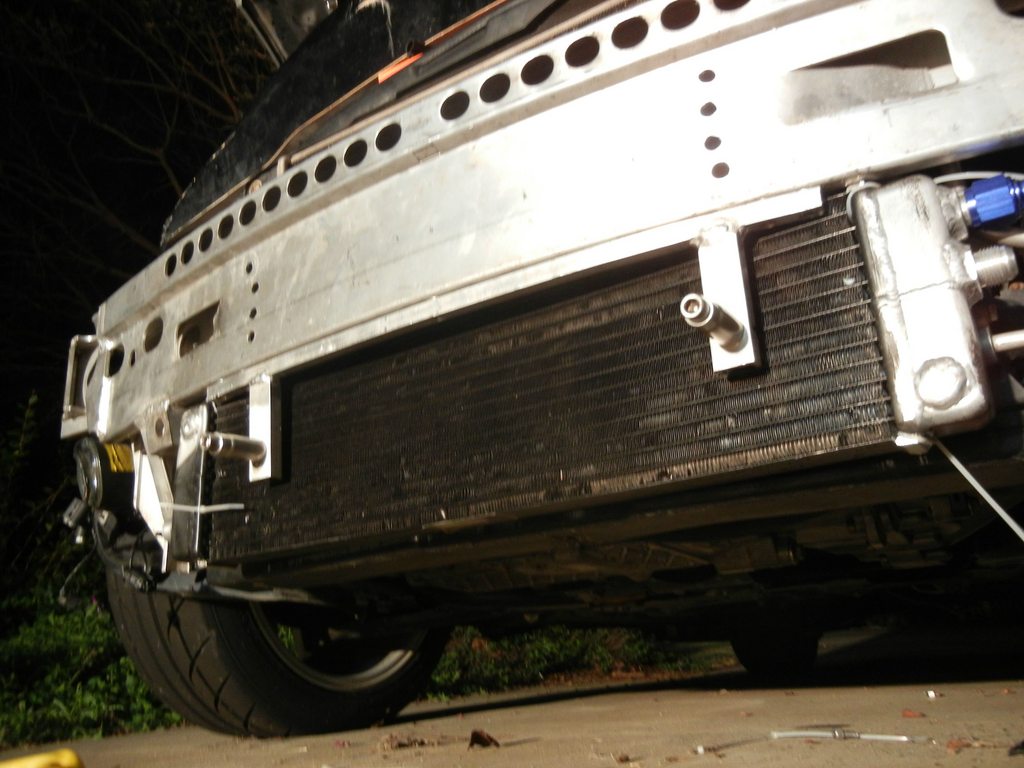
side view with bumper on

and then I went ahead and cut a 22" piece of the channel (same width as alta bar) and put two more 10mm holes in the front at 16.0625" OC (peg distance)
Still need to decide exactly how I want to mount the lights themselves (horizontal welded bracket or drill and bolt vertical and have no left or right adjustment)

that is all for today!
thoughts?