Low Speed Fan Resistor - we need solution


#52
 11-02-2009, 06:12 AM

4th Gear
Join Date: May 2009
Location: As Far North in NY as You Can Get
Posts: 324
Likes: 0
Received 0 Likes
on
0 Posts
Hmm, something else wrong w/ my special little car I didn't know was wrong until I read it here  - I just thought it was a single speed fan on a good cooling system, only running when it was really hot
  - anybody already have a good pic, or the dimensions of the OEM part, for comparison to Mouser part (1-1/16 x 2-7/16 x 15/16)? Or tried it yet?
From the Haynes manual (p. 3.4): "7. The existing resistor must be removed, and the new resistor soldered into place (see illustration). Check the availability of a new resistor before removing unsoldering the old one." (oddly written, but that's the way it's printed) Now, this is the British version manual, but implies (to me) replacing the resistor is SOP for repair...
Of course, it's November in Vermont, so no hurry I guess...
- I just thought it was a single speed fan on a good cooling system, only running when it was really hot - anybody already have a good pic, or the dimensions of the OEM part, for comparison to Mouser part (1-1/16 x 2-7/16 x 15/16)? Or tried it yet?From the Haynes manual (p. 3.4): "7. The existing resistor must be removed, and the new resistor soldered into place (see illustration). Check the availability of a new resistor before removing unsoldering the old one." (oddly written, but that's the way it's printed) Now, this is the British version manual, but implies (to me) replacing the resistor is SOP for repair...
Of course, it's November in Vermont, so no hurry I guess...
Last edited by DaveVT02S; 11-02-2009 at 06:36 AM.

#54
11-02-2009, 07:08 AM
If 30 A goes through a 1/3 ohm resistor, then v = ir = 10V,
and power would iv = 300W.
But I believe the resistor is in series with the fan motor, and it's
probably a lot less than 30 A with the resistor in the circuit.
If the fan is also 1/3 ohm resistance, then the current through
both would be 20A for 13V from the battery, and power would be 130W,
but then the fan would draw about 40A without the resistor in the circuit,
so that can't be right (it would blow the fuse).
If the fan was 2/3 ohm, then about 56W at the resistor (13A).
#55
11-02-2009, 07:35 AM
#56
11-02-2009, 07:58 AM
copied from post 30 above: I'd probably go with the first one.
I'll bet you this part would work: 0.33 ohm 100 W for $15, but has a 3 week leadtime.
Update: 10 on order, estimated ship date 11/6/09, 6 week factory leadtime.
http://www.mouser.com/ProductDetail/...P6X%252bS2M%3d
Could also try a 50 W one - cheaper, smaller, and in stock:
http://www.mouser.com/ProductDetail/...7avknkxuofQ%3d
Gotta love Mouser.com for finding electronic parts - they have a pretty good search function, too.
#58
11-02-2009, 09:30 AM
#59
11-02-2009, 10:34 AM
Cristo is right...
power is I^2*R. That's 900*.33, or 300 if the circuit ran at 30 amps... But it doesn't as then, as he points out, the fuse would blow on high speed. What's potentially nice about using these guys is that you could locate the resistor where ever you wanted and run a wire to the fan.... Like someplace it's easy to get to! Just make sure that it's in a place with really good airflow to keep it cool.
And to get all nerdy on this stuff, when I was reading about power resistors, the numbers we're quoting are steady state power ratings. For short durations, they can take a bigger power hit than the rated power. A lot goes into determining what is a "short duration"...
Matt
And to get all nerdy on this stuff, when I was reading about power resistors, the numbers we're quoting are steady state power ratings. For short durations, they can take a bigger power hit than the rated power. A lot goes into determining what is a "short duration"...
Matt
#60
11-02-2009, 01:59 PM

1st Gear
Join Date: Oct 2008
Location: near San Luis Obispo
Posts: 20
Likes: 0
Received 0 Likes
on
0 Posts
First post here...
...Hi NAM...okay, I have been lurking through and been a member of NAM for at least a year and I have been avoiding my first post; I guess I am not much of a joiner.  But I too suffer from the burnt out low stage resistor issue. So I thought I would add in. Through Ebay I ended up with a new OEM fan assembly (two actually) both units measure out at .3 ohms and that is both measured with my Fluke and one with my Radio Shack something or another VOM. One of my Double E buddies keeps pestering me about (him) making a FET solid state controller to have a soft start fan kick on and maybe an additional output to trigger some other do-dad...sounds great to me, but he'll never get around to it (he's a Subaru guy, they are all talk
  ). This sounds like something the good Dr. at FES Auto might be able to engineer and piece together. I would happily give up some of my mad mod money to loose that cursed resistor, have soft start and more whiz-bang-cool stuff... just my first post and two cents.
But I too suffer from the burnt out low stage resistor issue. So I thought I would add in. Through Ebay I ended up with a new OEM fan assembly (two actually) both units measure out at .3 ohms and that is both measured with my Fluke and one with my Radio Shack something or another VOM. One of my Double E buddies keeps pestering me about (him) making a FET solid state controller to have a soft start fan kick on and maybe an additional output to trigger some other do-dad...sounds great to me, but he'll never get around to it (he's a Subaru guy, they are all talk ). This sounds like something the good Dr. at FES Auto might be able to engineer and piece together. I would happily give up some of my mad mod money to loose that cursed resistor, have soft start and more whiz-bang-cool stuff... just my first post and two cents.
#61
11-02-2009, 02:18 PM
#62
11-02-2009, 04:34 PM
1st Gear
Join Date: Oct 2008
Location: near San Luis Obispo
Posts: 20
Likes: 0
Received 0 Likes
on
0 Posts
Yes, those are the same numbers I had come up with prior to my Evilbay find. I was going to order that unit and hack it in as Dr. Obnxs suggests. With placement on the front side of the radiator support so I could keep an eye on it. Yes, I will continue to push my EE buddy to design up a solid state circuit, but really that is liking pushing a rope...he just doesn't have any MINI lust and thus not enough motivation. FES Auto and GBMINI are the type of guys that could actually get it done and have the vested interest (MINI love)! Additionally and this is the same as some previous post out there...my old broken unit is labeled as R34...and that coincides to the .34 ohm value mentioned in some other posts.
#63
11-02-2009, 07:42 PM

#64
11-03-2009, 07:18 AM
Not sure abotu a solid state solution...
as it's just not very cost effective to do it. Basically controlling that kind of ampereage via a solid state device would need to dissipate the power somewhere, or one would have to use a DC/DC switcher to make it so you're not just wasting the energy in the voltage step down stage. I'll look into it, but at first guess it doesn't really sound like an economic winner.
If one were to assume that the low side is running at about 22 amps, then a 150-200 W resistor would be better. 17A or so would be 100 W. Anyone measure the actual voltage across the resistor when it's running?
Matt
If one were to assume that the low side is running at about 22 amps, then a 150-200 W resistor would be better. 17A or so would be 100 W. Anyone measure the actual voltage across the resistor when it's running?
Matt
#65
11-03-2009, 08:51 AM
1st Gear
Join Date: Oct 2008
Location: near San Luis Obispo
Posts: 20
Likes: 0
Received 0 Likes
on
0 Posts
#66
11-03-2009, 09:13 AM
4th Gear
Join Date: May 2009
Location: As Far North in NY as You Can Get
Posts: 324
Likes: 0
Received 0 Likes
on
0 Posts
Naw, I think this is the right thread ("we need a solution")...
Just keep in mind that with electric motors you'll be dealing with 2 different amp ratings: a start up load (always happens, every time, running load is less) and a LRA rating (locked rotor amps, as if you grabbed the blade and stopped it at full speed, higher draw), which is where the fuse should blow (possibly with a delay circuit). An electronic part that fails repeatedly and prematurely from normal use is a failed design...
Please carry on - even failures get us closer to an answer ...
...
Just keep in mind that with electric motors you'll be dealing with 2 different amp ratings: a start up load (always happens, every time, running load is less) and a LRA rating (locked rotor amps, as if you grabbed the blade and stopped it at full speed, higher draw), which is where the fuse should blow (possibly with a delay circuit). An electronic part that fails repeatedly and prematurely from normal use is a failed design...
Please carry on - even failures get us closer to an answer
...
#67
11-19-2009, 03:52 PM
#68
11-20-2009, 04:59 AM
#69
11-20-2009, 06:13 PM

 [/IMG]
#70
01-06-2010, 06:46 AM

2nd Gear
Join Date: Jun 2009
Location: New Orleans, Louisiana
Posts: 60
Likes: 0
Received 0 Likes
on
0 Posts
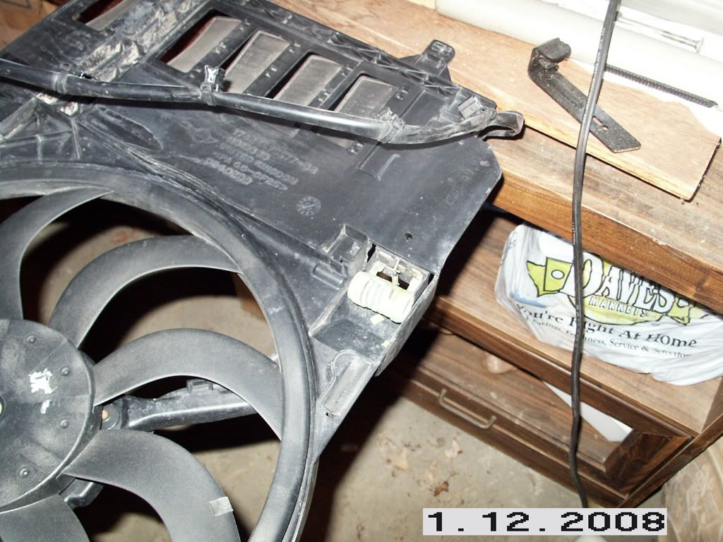
Based on this photo from "gclass" in this thread:
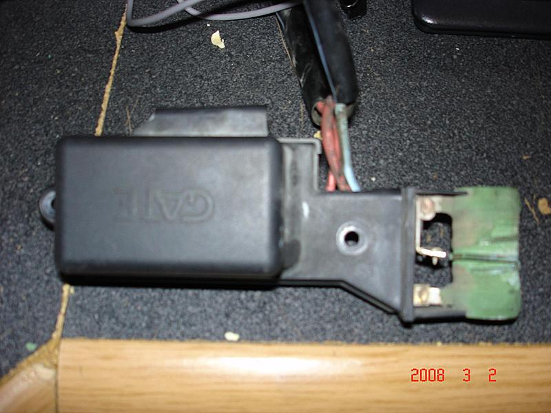
It *looks* like there is a center 'tap' to the resistor in which case it may be set up as a voltage divider.
Can anyone comment on whether the top and mid taps are connected (other than through the resistor)? This photo is too blurry and the wrong angle.
Another thought I had was that it might be possible bypass the 'luxury' low-speed all-together and tie the high speed circuit into the low-speed's sensor. Then you would at least get cooling at the lower setpoint by sacrificing a bit of 'comfort.' This might be really easy depending on how the wiring is setup...
Regards,
Sten
#71
01-06-2010, 07:00 AM
4th Gear
Join Date: May 2009
Location: As Far North in NY as You Can Get
Posts: 324
Likes: 0
Received 0 Likes
on
0 Posts
#72
01-06-2010, 07:05 AM
Anyheck: I'm the one that started this thread; thanks for the update; this is the first I have learned of the 'voltage divider' aspect to this problem. I have not yet disassembled my front end to explore substitution of the wire wound resistor I bought from Mouser Electronics, but if what you suspect is true, it probably won't work.
#73
01-06-2010, 07:22 AM
2nd Gear
Join Date: Jun 2009
Location: New Orleans, Louisiana
Posts: 60
Likes: 0
Received 0 Likes
on
0 Posts
I'm honestly not sure why one would use a voltage divider in this type of setup, but without seeing the circuit diagram or tracing it myself, the center tap is puzzling. Usually it's used as a voltage reference. A series resistor is usually used for voltage reduction, just as you initially thought.
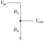
A voltage divider is trivial to replicate even if you don't have the custom resistor, you just use two resistors in series and 'tap' the central connection.
this is from the wikipedia page:
A voltage divider is trivial to replicate even if you don't have the custom resistor, you just use two resistors in series and 'tap' the central connection.
this is from the wikipedia page:
#74
01-06-2010, 11:42 AM
It can also be a poor mans speed control
where low speed sees R1+R2 and high speed sees just R2. But in general, this is dumb because then the R2 has to be able to handle the higher current, and the windings for R1 are then much thicker wire (hence more expensive) than need to be.
AS mentioned before, it can be for a feedback to sense that the relay hasn't died and that the circuit is getting voltage. If that's the case, a high resistance devider in parallel can be used to do the same thing.
Matt
AS mentioned before, it can be for a feedback to sense that the relay hasn't died and that the circuit is getting voltage. If that's the case, a high resistance devider in parallel can be used to do the same thing.
Matt
#75
01-06-2010, 04:03 PM
2nd Gear
Join Date: Jun 2009
Location: New Orleans, Louisiana
Posts: 60
Likes: 0
Received 0 Likes
on
0 Posts
Not to confuse things more, but a possible alternative design to the resistor to maintain a low-speed setting would be to use a solid-state relay such as those seen here (up to 15 Khz PWM):
http://www.power-io.com/products/hdd.htm
and control that with a low-cost Pulse Width Modulation circuit some thing like what is seen here:
http://www.dprg.org/tutorials/2005-11a/index.html
And that would be activated by the built-in relay/temp control.
More expensive than the resistor option, but it would contain more geek cred.