Drivetrain My build. Teaser photos and updates


#52
 10-10-2013, 04:53 AM

That's what I was wondering. There doesn't' appear to be much of a gap for air to get through the fins....if all of the fins are that close and touching each other, doesn't that negate the whole concept of having all of those fins to transfer heat?
#53
10-10-2013, 05:14 AM

http://www.laminova.se/cooler-guide/intercooler/
I will update with some more info when I get to work, but these are designed for 2.5mm of core length per horsepower of air flow @ a 0.5psi pressure drop across the core.
Engines make power by pumping air, so the horsepower term is using heuristics in terms of an average engines efficiency and the amount of air it needs to make a "horse power".
This first set of cores (the three in the first exchanger) should only have 0.5psi of pressure drop at 282 hp, more hp (more flow) just gives you a little more pressure drop
Let me know if there are any more questions!
And yes I said first. Currently working on measuring/designing/finding materials to make one that is integrated into the intake manifold. Air will come out of the SC and go straight into the intercooler and straight into the intake runners. No piping or bends!)
As to the lights, they are PIAA 600 series. I have 4 of them, but planning on only running two most of the time (they have 55 watt HID ballasts and bulbs in them. will blind anything on the road, but hey, they shouldnt be on if someone is in front of me) . May mount all 4 up if I am headed to the dragon for a night run or something though
Last edited by soccerbummer1104; 10-10-2013 at 05:46 AM.
#54
10-10-2013, 07:46 AM

I believe that IQraceworks was commenting on the spacing of the fins on the outside of the cores and was wondering that since the fins are so close together does it decrease their ability to dissipate heat. And was there any fluid dynamics testing/calculations performed to verify this.
Looking at the manufacturers website I believe that the answers would be that the spacing is somewhat optimal and yes they have been tested.
Looking at the manufacturers website I believe that the answers would be that the spacing is somewhat optimal and yes they have been tested.
#55
10-11-2013, 08:08 PM
#56
10-11-2013, 08:43 PM


#57
10-12-2013, 08:28 AM
#59
10-26-2013, 06:17 PM
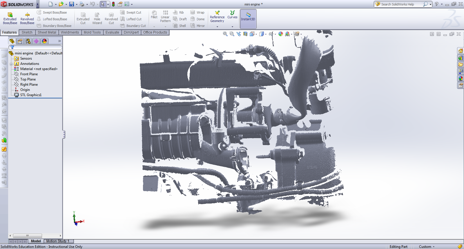
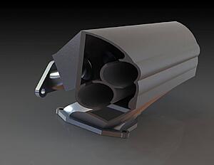
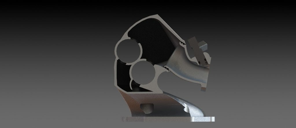
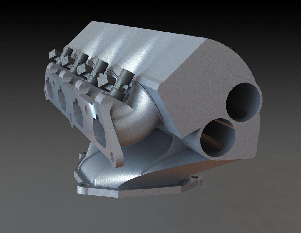
well the reason for the scans ^^ was to make sure I got ALL of the friggin angles and clearances correct for designing this.
Currently my computer (other one) is trying to crunch the numbers on the flow through this thing (without cores installed) at 5000 RPM in solidworks... may post that up later..
For now, this will just let me know who all it watching this thread still. haha!
still need to
Currently my computer (other one) is trying to crunch the numbers on the flow through this thing (without cores installed) at 5000 RPM in solidworks... may post that up later..
For now, this will just let me know who all it watching this thread still. haha!
still need to
- add injector fittings
- add o-ring grooves (this is actually two parts)
- add BPV take off
- add MAP sensor port
- finish the mounting points for the water inlet outlet, and the back-side turn around (these cores will be in series and not parallel like the other cooler)


#61
10-26-2013, 08:01 PM

5th Gear
Join Date: Jul 2012
Location: Richardson, TX
Posts: 777
Likes: 0
Received 0 Likes
on
0 Posts
#62
10-26-2013, 09:01 PM

5th Gear
#63
10-26-2013, 09:15 PM
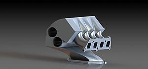
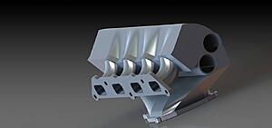
sending the file out to a casting company monday to get a quote.
I have an upper limit on price for this one piece, and if they meet it I will pull the trigger.
Company I am dealing with has done some stuff for my work before, and we know they will do a one-off investment cast.
They print the part itself on a SLA 3d printer and use that instead of wax to make the mold and investment cast the part.
Saves on tooling for a single or low number production run, but this is a large and complicated part...

#66
10-27-2013, 11:33 PM

#67
11-03-2013, 11:23 AM

Peace Keeper
#68
11-03-2013, 06:57 PM
thanks guys!
Another panning video. Quote for the casting should be in sometime this week. Then it is to tweaking to make sure it comes out okay.
www.youtube.com/embed/GetZ93M4c0g
Another panning video. Quote for the casting should be in sometime this week. Then it is to tweaking to make sure it comes out okay.
www.youtube.com/embed/GetZ93M4c0g
Last edited by soccerbummer1104; 11-03-2013 at 07:04 PM.
#69
11-12-2013, 07:48 AM
update: some good and bad.
Bad: investment casting is NOT happening. I actually started laughing when I saw the quote. I think it was just because the part was semi complex and for a one-off they did not want to deal with it so they priced it silly high. (we are talking $10,000 for 1 of these)
the good! I am making it a different way! and should remain on budget.
good #2 : I get to expand my working knowledge of composites even more! (I have done some work before, but never this complex and multi-part)
good # 3! : this is on order and should be here somepoint soon.
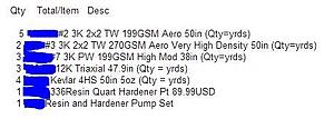
Still working on the models for the tooling molds, but they are coming along.
#70
11-12-2013, 01:46 PM
Peace Keeper


#72
11-19-2013, 09:25 PM
and another ADHD fueled and shitty phone pic update!
Decided to start working on the SC inlet tube as I was bored at home last evening.
Started working on the tube itself this evening, but no pictures of that.
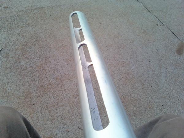
started by measuring the stock tube carefully, drawing it up in solidworks, printing, cutting out of paper, and laying the paper inside of the stock tube to make sure the profile was correct.
Once that was finished I transferred the stencil to some 1/8" aluminum sheet and cut out the outside path and drilled the "path" for the SC port (port-matched)
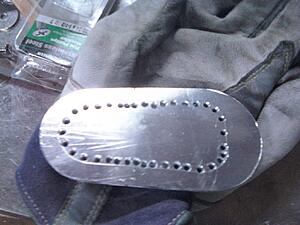
test fit is next
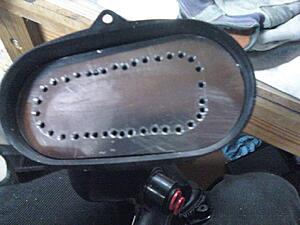
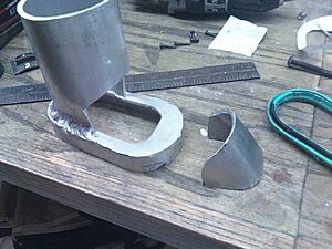
I then cut a strip of .080" thick ~.75" wide out of a sheet and used that to form and weld the "lip" that holds the gasket.
test fit again. EXTREEMLY snug. like a glove.
next up I used the rotozip (like a large dremmel tool) and a 1/8" end mill I picked up at travers tool and cut out the inside profile.
Finished it up with a rotary file in a drill and then followed with a finish profile handfile
As for today?
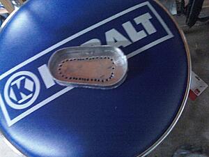
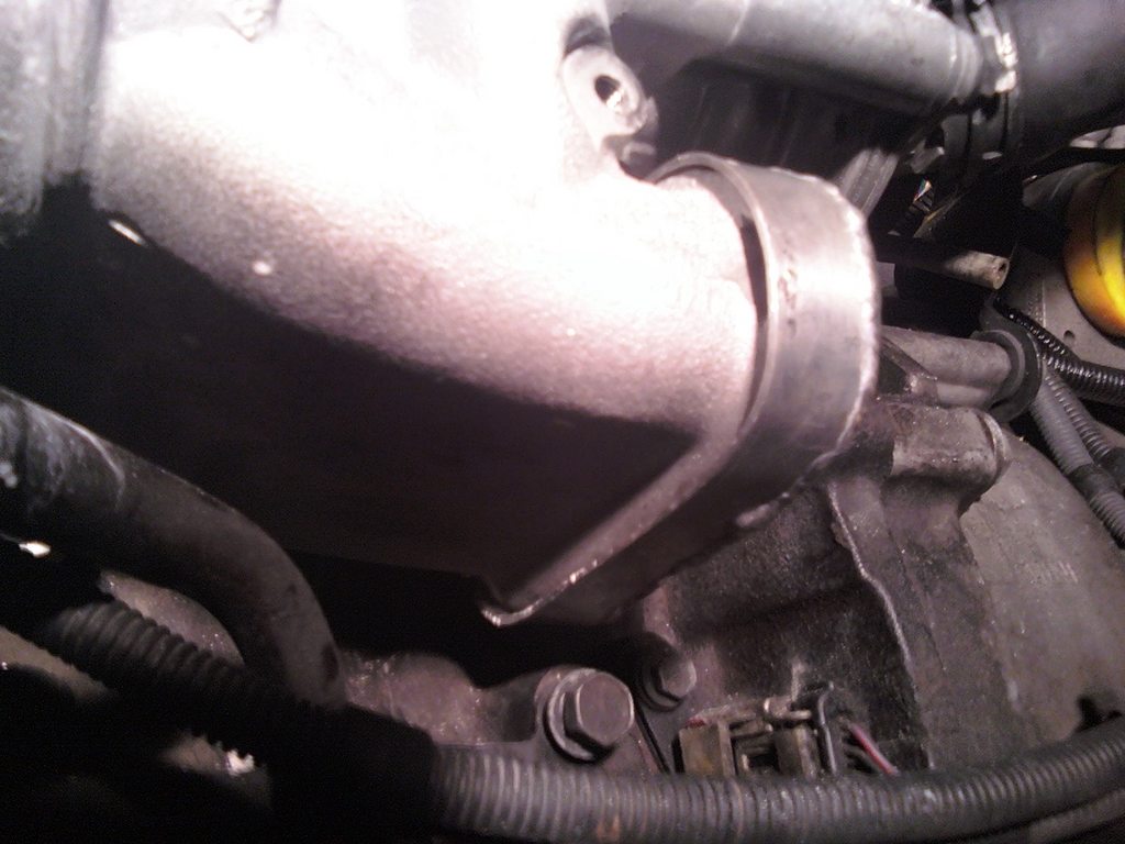
Ground the welds and filed the back side completely flat by hand, then took some 2.5" pipe, cut, crushed, pofiled, etc, to get it to loft from the 2.5" to the inlet oval (smooth transition) and clear pump fan, transmission, etc.
in other EXTREEMLY non related news.
Almost done with the main mechanism on my TV mount! (for the apartment)
Decided to start working on the SC inlet tube as I was bored at home last evening.
Started working on the tube itself this evening, but no pictures of that.
started by measuring the stock tube carefully, drawing it up in solidworks, printing, cutting out of paper, and laying the paper inside of the stock tube to make sure the profile was correct.
Once that was finished I transferred the stencil to some 1/8" aluminum sheet and cut out the outside path and drilled the "path" for the SC port (port-matched)

test fit is next

I then cut a strip of .080" thick ~.75" wide out of a sheet and used that to form and weld the "lip" that holds the gasket.

test fit again. EXTREEMLY snug. like a glove.

next up I used the rotozip (like a large dremmel tool) and a 1/8" end mill I picked up at travers tool and cut out the inside profile.
Finished it up with a rotary file in a drill and then followed with a finish profile handfile

As for today?
Ground the welds and filed the back side completely flat by hand, then took some 2.5" pipe, cut, crushed, pofiled, etc, to get it to loft from the 2.5" to the inlet oval (smooth transition) and clear pump fan, transmission, etc.
in other EXTREEMLY non related news.
Almost done with the main mechanism on my TV mount! (for the apartment)
Last edited by soccerbummer1104; 08-27-2014 at 08:08 AM.
#74
11-20-2013, 07:26 PM
haha. don't sweat it. I have a lot of free time and have always loved to make things with my hands.
you should have seen some of the **** I made with lego's when I was 12. My dad (physician but former aerospace engineer for lockeed martin) would often raise eyes as to "how in the world did you come up with that?"
a little about me, since none of you know.
I am a 22 year old ( I am the "youngun" at work) development engineer for an F500 company.
Background is in chemical engineering (focus was biomolecular) yet I work to develop innovations in the performance films industry (primarily shrink)
I am (obviously) quite mechanically minded however (an oddity among chemical engineers) and actually spend half of my time designing mechanical solutions to equipment needs in the pilot plant or in development scale up.
Also do some work with tech scouting (finding new technologies)
Some of my co-horts at work call me "Jack" due to my multi-functional "tallents" (my name is Brad.. )
enough about me though.
Did not have a whole lot of time to work on it today. We have our thanksgiving lunch at work tomorrow and I am making two Pecan Pies. (I also cook / chef it up. We are talking made beignet's and banana's foster this past weekend for some friends - level cooking, although Chocolate mousse cake with meringue tiers or brulee are my specialties in the desert world.)
but anywho.
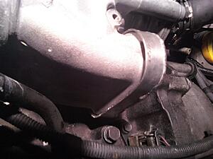
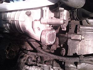
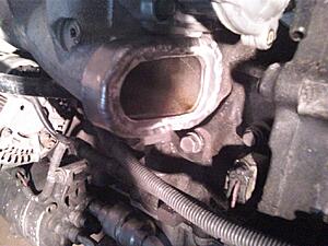
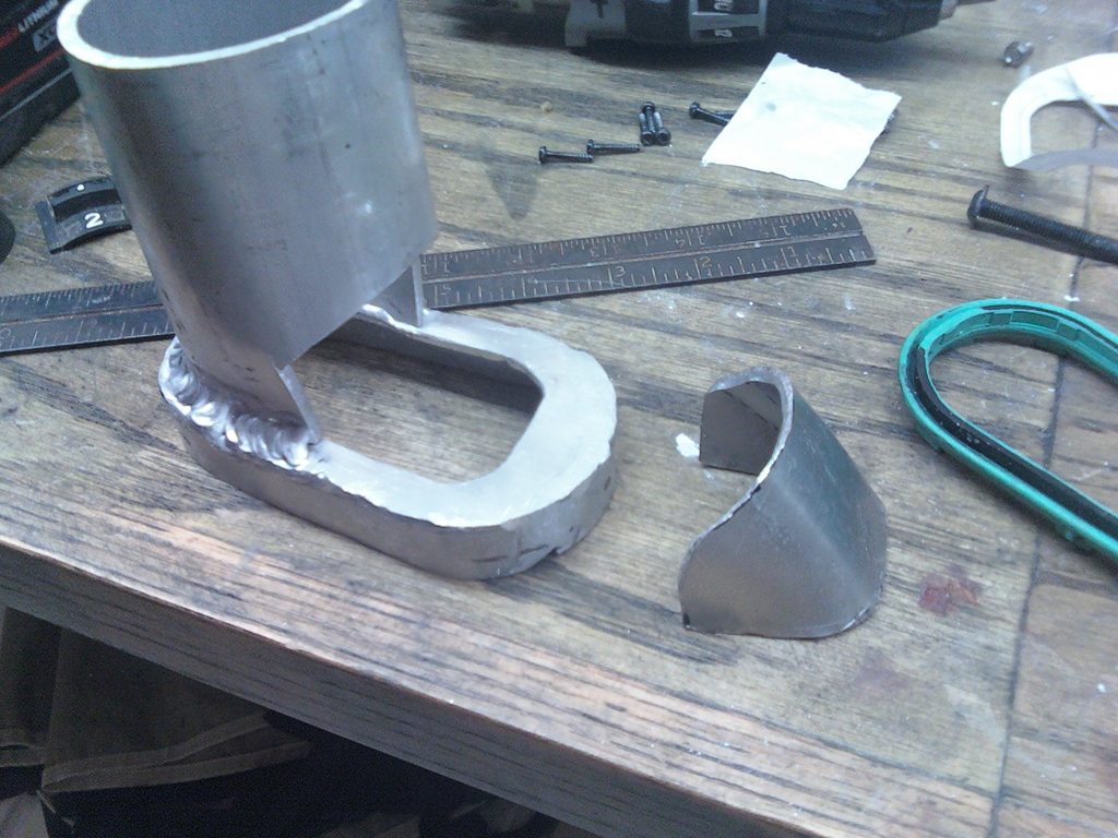
notched and crushed a pipe slightly, then took a soft blow hammer to it on a sand bag to form the pipe to the contour of the SC inlet and then cut out a piece of metal from sheet stock, clamped it in the vice, annealed it, and then formed it with the hammer in a vice.
Welded it all up and!!
before "notch" piece was welded in
and after!!
ground down the weld on the inside (welded in and out), but still need to polish it out more.
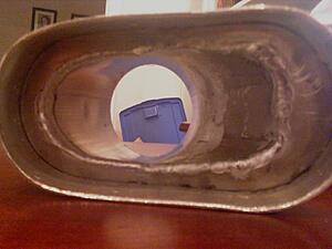
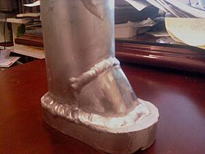
Enjoy!
Not the prettiest thing in the world, but I am actually a little surprised it came out this nicely! haha.
you should have seen some of the **** I made with lego's when I was 12. My dad (physician but former aerospace engineer for lockeed martin) would often raise eyes as to "how in the world did you come up with that?"
a little about me, since none of you know.
I am a 22 year old (
I am the "youngun" at work) development engineer for an F500 company. Background is in chemical engineering (focus was biomolecular) yet I work to develop innovations in the performance films industry (primarily shrink)
I am (obviously) quite mechanically minded however (an oddity among chemical engineers) and actually spend half of my time designing mechanical solutions to equipment needs in the pilot plant or in development scale up.
Also do some work with tech scouting (finding new technologies)
Some of my co-horts at work call me "Jack" due to my multi-functional "tallents" (my name is Brad.. )
enough about me though.
Did not have a whole lot of time to work on it today. We have our thanksgiving lunch at work tomorrow and I am making two Pecan Pies. (I also cook / chef it up. We are talking made beignet's and banana's foster this past weekend for some friends - level cooking, although Chocolate mousse cake with meringue tiers or brulee are my specialties in the desert world.)
but anywho.
notched and crushed a pipe slightly, then took a soft blow hammer to it on a sand bag to form the pipe to the contour of the SC inlet and then cut out a piece of metal from sheet stock, clamped it in the vice, annealed it, and then formed it with the hammer in a vice.
Welded it all up and!!
before "notch" piece was welded in
and after!!
ground down the weld on the inside (welded in and out), but still need to polish it out more.


Enjoy!
Not the prettiest thing in the world, but I am actually a little surprised it came out this nicely! haha.
#75
11-20-2013, 07:55 PM
